Chapter.4 System equipment
4-4
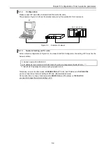
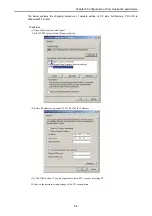
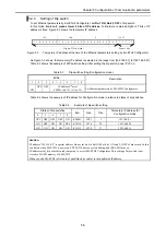
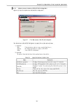
4.2.1 STS
LED
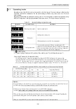
STS LED blinks with turning on ERR LED or IER LED, when EH-ETH2 has been detected an error. Table
4.4 shows Error class corresponding between STS LED’s blinking pattern and LED turns on concurrently
with.
Table 4.4
Error class corresponding between STS LED’s blinking pattern and LED turns on concurrently with
Error class
Number of
blinking
with ERR LED
with IER LED
1
ASR connection open error
Ethernet Information setting error
2
ASR send error
ASR Information setting error
3
ASR receive error
-
4
Task cord communication error
Error of temporally IP address for Configuration mode
1-time blinking
ON
OFF
0
0.25 0.5 0.75 1.0 1.25 1.5 1.75 2.0 2.25 2.5 2.75 3.0 3.25
3.50
3.75
(s)
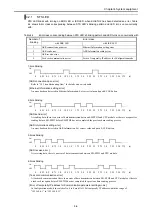
[ ASR connection open error ]
Refer to “10.1 troubleshooting flow” for details on how to handle.
[ Ethernet Information setting error ]
An error has been detected in Ethernet Information. Set correct value and push E.CLR button.
2-time blinking
ON
OFF
0
0.25 0.5 0.75 1.0 1.25 1.5 1.75 2.0 2.25 2.5 2.75 3.0 3.25
3.50
3.75
(s)
[ ASR send error ]
At sending data, there is an error of data transmission between EH-ETH2 and CPU module or there is a request for
sending data to EH-ETH2 before EH-ETH2 has not completed the previous data sending process.
[ ASR Information setting error ]
An error has been detected in ASR Information. Set correct value and push E.CLR button.
3-times blinking
ON
OFF
0
0.25 0.5 0.75 1.0 1.25 1.5 1.75 2.0 2.25 2.5 2.75 3.0 3.25
3.50
3.75
(s)
[ ASR receive error ]
At receiving data, there is an error of data transmission between EH-ETH2 and CPU module.
4-times blinking
ON
OFF
0
0.25 0.5 0.75 1.0 1.25 1.5 1.75 2.0 2.25 2.5 2.75 3.0 3.25
3.50
3.75
(s)
[ Task cord communication error ]
At task cord communication, there is an error of data transmission between EH-ETH2 and CPU module or there is
a task cord reception before EH-ETH2 has not completed the previous data sending process.
[ Error of temporally IP address for Communication parameter setting mode ]
In Configuration mode, dip switches No.4 to 8 are all off. Set temporally IP address within the range of
“192.168.0.1” to “192.168.0.31”.


