Chapter 5 Configuration of Communication parameters
5.3
Configuration of Ethernet parameters by user program
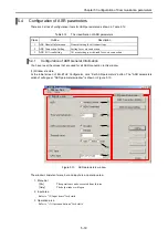
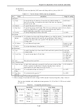
(1) Setting the dip switch
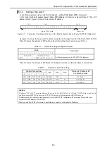
To configure the Ethernet parameters by the user program, setting dip switch No.4 and No.6 are ON is
required.
Table 5.9
Setting the dip switch (Configuration Ethernet parameters by the user program)
Dip switches
Description
[ No.4, 6 are ON ]
1 2
5 6
3 4
7 8
ON
To configure the Ethernet parameters by the user program.
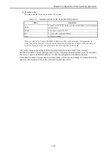
CAUTION
- It is possible to access to this module by EH-ETH2 Configurator at this mode but it is not possible to change the
“Ethernet parameters” by EH-ETH2 Configurator.
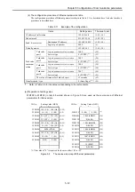
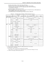
(2) Table of Ethernet parameters
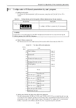
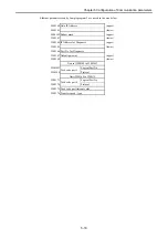
The Ethernet parameters into retained memory of this module with the format shown in Table 5.10.
Table 5.10
The table of Ethernet parameters
I/O No.
offset
items
+00 Own IP address
(upper)
+01
(lower)
+02 Subnet mask
(upper)
+03
(lower)
+04 Destination IP address for test
(upper)
+05
(lower)
+06 Destination Port No. for test
+07 Default gateway
(upper)
+08
(lower)
+09
:
No use
+2C
+2D
Logical Port No.
+2E
Task code port 1
Protocol
+2F
Logical Port No.
+30
Task code port 2
Protocol
+31
Logical Port No.
+32
Task code port 3
Protocol
+33
Logical Port No.
+34
Task code port 4
Protocol
+35 Task code port timeout value
+36 Transfer speed / type
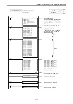
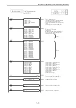
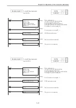
(3) Setting and referring the table value of Ethernet parameters
The dedicated commands (FUN200 on EH-150 series, XYRW on EHV-CPU series) should be used for setting
or referring the value of Ethernet parameters of this module. These commands handle the data transfer between
internal memory area of CPU and the retained memory of this module. The continuously 55 words of internal
memory is required to set the Ethernet parameters by the user program using these commands.
5-11

