Chapter 3 Programming
3
– 41
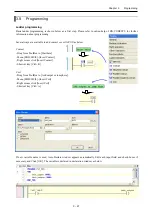
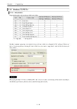
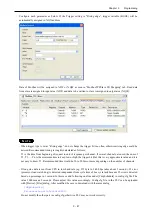
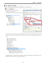
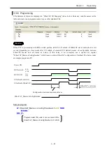
Configure each parameter as below. If the Trigger setting is “Rising edge”, trigger variable (BOOL) will be
automatically assigned in %QX address.
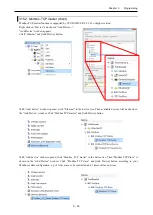
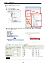
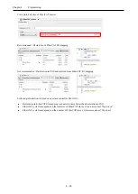
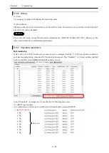
Data of Modbus will be assigned to %IW or %QW as seen in “ModbusTCPSlave I/O Mapping” tab. Read data
from slave is assigned to input area (%IW) and data to be written to slave is assigned to output area (%QW).
N o t e
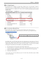
- When trigger type is set as “Rising edge”, do not change the trigger bit too often, otherwise rising edge could be
missed. Recommended timing is roughly calculated as follows.
T1 is the time from beginning of request to end of response per channel. If several channels are used, the sum of
T1, T2, ..., Tn is the minimum time to keep low or high the trigger bit. But this is very approximate value and it is
not easy to know T1. Recommended time would be 50 to 200ms or more depending on the number of channels.
- If long size data is sent from CPU in low baud rate (eg. 255 byte in 2,400 bps takes about 1 second.), 25 error
(processor load watch dog) is detected independent from cycle time of bus cycle task because 25 error is detected
based on percentage in 1 second. In this case, add following one line under [CmpSchedule] in config.cfg file. The
value 2000 means 2 seconds. Please adjust this value accordingly. Config.cfg file in the PLC can be uploaded
with [Device]-[Files] dialog. After modified, be sure to download with the same dialog.
[CmpSchedule]
ProcessorLoad.Interval=2000
Do not modify the other part in config.cfg, otherwise PLC may not work correctly.
Summary of Contents for EH-A14EDR
Page 6: ...MEMO ...
Page 10: ...MEMO ...
Page 141: ...Chapter 3 Programming 3 81 Program ...
Page 166: ...Chapter 5 Maintenance 5 4 MEMO ...
Page 170: ...Appendix A1 4 MEMO ...

