Chapter 2 Specifications
2
– 7
2.6
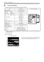
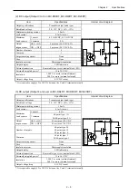
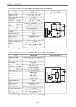
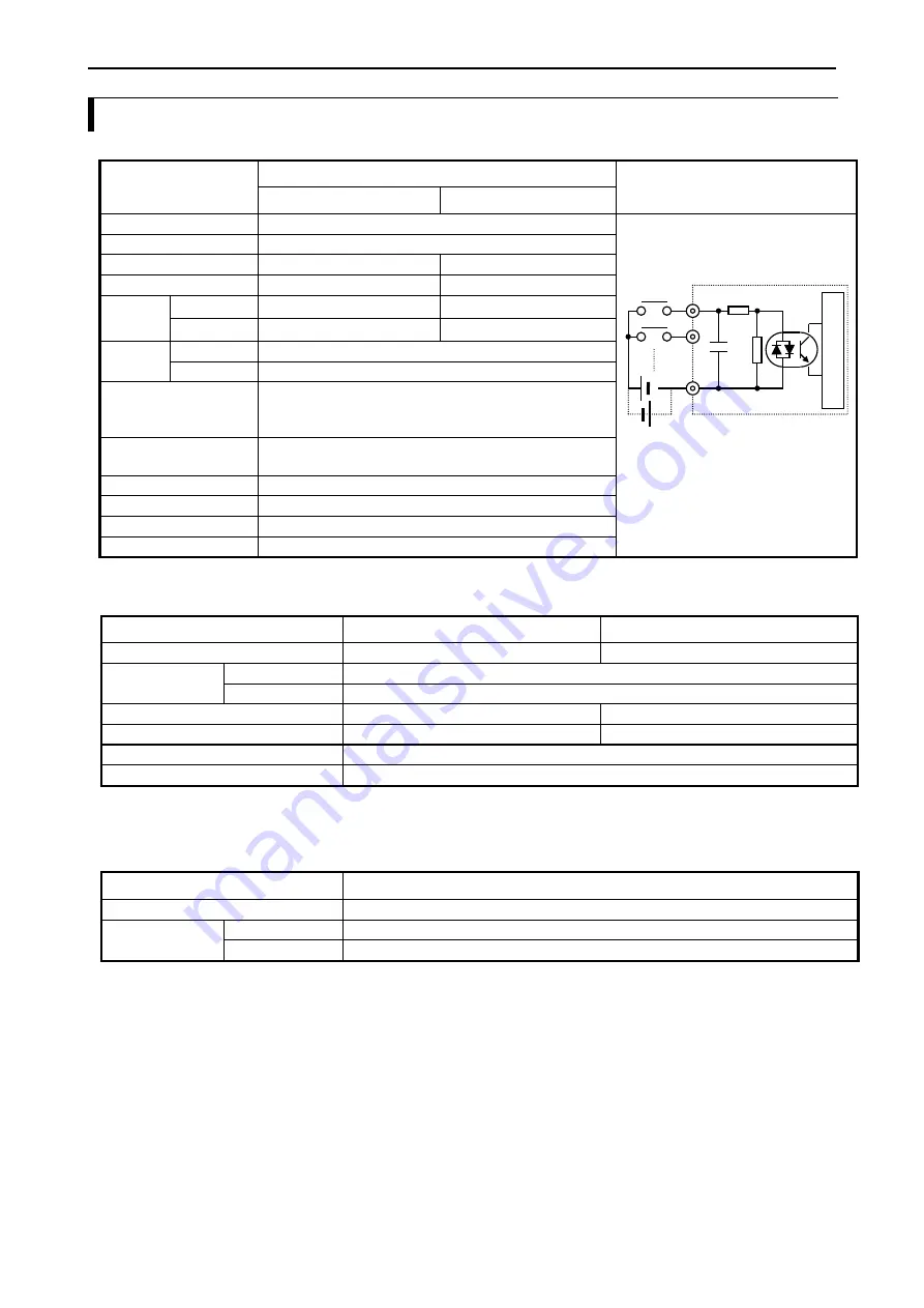
Input specifications
Item
Specification
Internal circuit diagram
bit 0, 2, 4, 6, 8
Others
Input voltage
24V DC
Allowable input voltage range
0 to 30V DC
Input impedance
Approx. 2.7 kΩ
Approx. 4.7 kΩ
Input current
8 mA typical
4.8 mA typical
Operating
voltage
ON
18 VDC
(min)
/ 4.5mA
(max)
18 VDC
(min)
/ 3.3mA
(max)
OFF
5 VDC
(max)
/ 1.8mA
(max)
5 VDC
(max)
/ 1.6mA
(max)
Input lag
OFF → ON
0.5 to 20 ms (configurable)
ON → OFF
0.5 to 20 ms (configurable)
Number of inputs
64-point type: 40
40-point type: 24
20-point type: 12
Common
40/64-point type: 2
20-point type: 1
Polarity
None
Insulation system
Photocoupler insulation
Input display
LED indication
External
Removable type screw terminal block (M3)
■ High-speed counter specifications
Item
Single phase
2-phase
Input
Bit 0, 2, 4, 6, 8
Bit 0 and 2, Bit 4 and 6
Input voltage
ON
18 V
OFF
5 V
Count pulse width
10 μs
17 μs
Highest counting frequency
100 kHz each channels
60 kHz each channels
Count Register
32-bit
On / Off-preset
Available
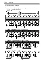
Refer to page 4-5 for wiring to a rotary encoder.
■ Interrupt input specifications
Item
Specification
Input
1, 3, 5, 7, 9
Input voltage
ON
18 V
OFF
5 V
In
te
rn
a
l
c
ir
c
u
it
0
1
C
Summary of Contents for EH-A14EDR
Page 6: ...MEMO ...
Page 10: ...MEMO ...
Page 141: ...Chapter 3 Programming 3 81 Program ...
Page 166: ...Chapter 5 Maintenance 5 4 MEMO ...
Page 170: ...Appendix A1 4 MEMO ...

