Chapter 2 Specifications
2
– 10
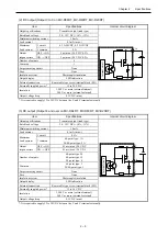
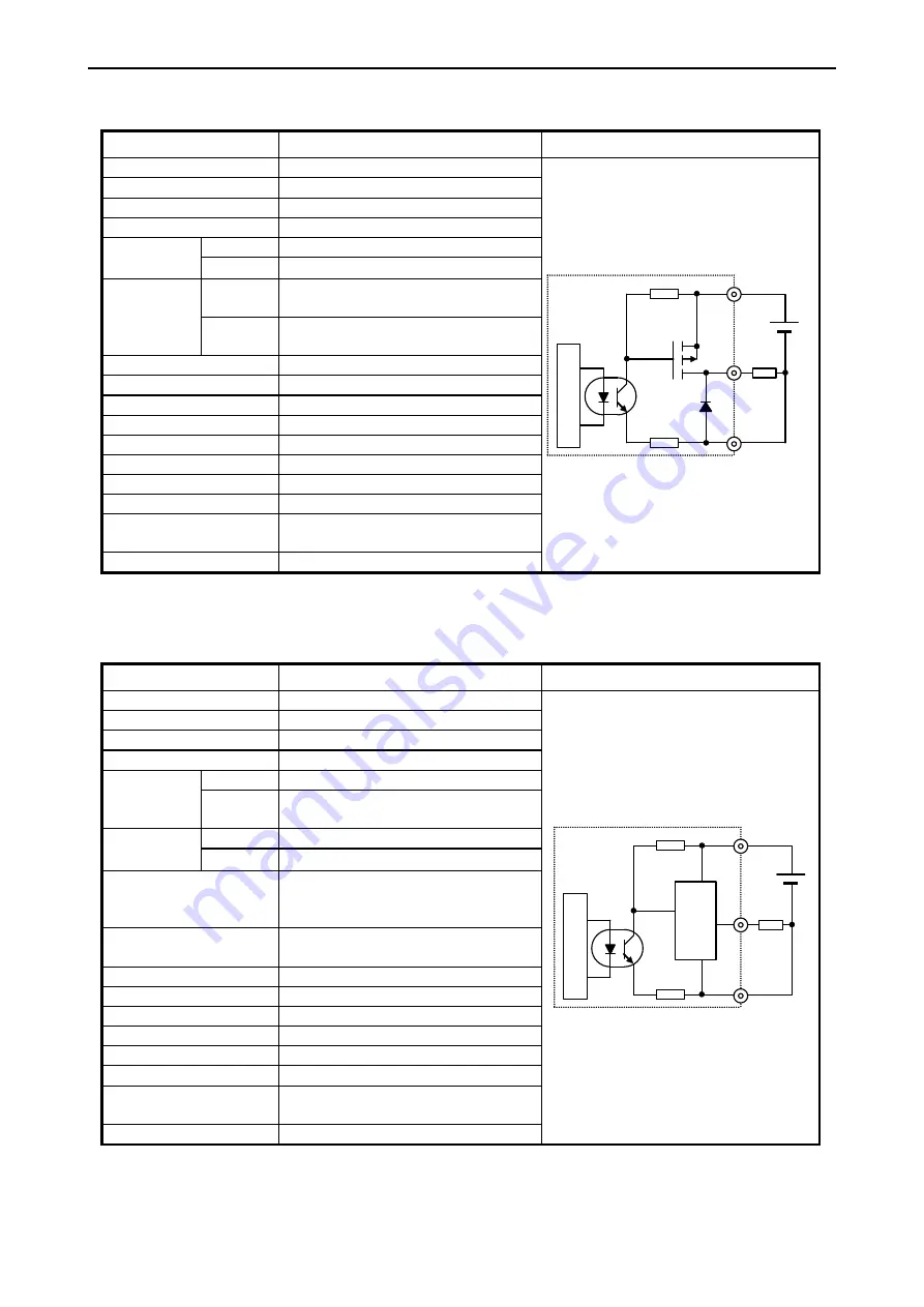
(4) DC output (Output 0 to 3 on MV-D64DTPS, MV-D40DTPS, MV-D20DTPS)
Item
Specifications
Internal circuit diagram
Output specifications
Transistor output (Source type)
In
te
rn
al
circ
u
it
V10
0
C10
Rated load voltage
24 / 12 V DC (+10%, -15%)
Minimum switching current
10 mA
Leak current
0.1 mA (max.)
Maximum
Load current
1 circuit
0.5 A 24VDC, 0.3 A 12VDC
1 common
2 A
Output
response time
OFF → ON
Output 0 to 2: 5 μs (max.) 24 V DC 0.2 A
Output 3: 0.5 ms (max.) 24 V DC
ON → OFF
Output 0 to 2: 5 μs (max.) 24 V DC 0.2 A
Output 3: 0.5 ms (max.) 24 V DC
Number of outputs
4
Common
1
Surge removing circuit
None
Fuse
None
Insulation system
Photocoupler insulation
Output display
LED indication
External connection
Removable type screw terminal block (M3)
Externally supplied power *
12 to 30 V DC
Insulation
1,500 V or more (external-internal)
500 V or more (external-external)
Output voltage drop
0.3 V DC (max.)
*: It is required to supply 12 to 30V DC between the V and C terminal externally.
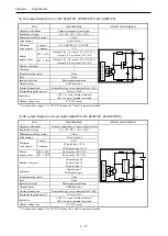
(5) DC output (Output 4 and over on MV-D64DTPS, MV-D40DTPS, MV-D20DTPS)
Item
Specifications
Internal circuit diagram
Output specifications
Transistor output (Source, short circuit protection)
In
te
rn
al
circ
u
it
V
4
C10
Sh
o
rt
circ
u
it
p
ro
te
ctio
n
Rated load voltage
24 / 12 V DC (+10%, -15%)
Minimum switching current
10 mA
Leak current
0.1 mA (max.)
Maximum
Load current
1 circuit
0.7 A
1 common
64-point type: 3.0 A
20/40-point type: 5.0 A
Output
response time
OFF → ON
0.5 ms (max.) 24 V DC
ON → OFF
0.5 ms (max.) 24 V DC
Number of outputs
64-point type: 20
40-point type: 12
20-point type: 4
Common
64point type: 3
20/40-point type: 1
Surge removing circuit
None
Fuse
None
Insulation system
Photocoupler insulation
Output display
LED indication
External connection
Removable type screw terminal block (M3)
Externally supplied power *
12 to 30 V DC
Insulation
1,500 V or more (external-internal)
500 V or more (external-external)
Output voltage drop
0.3 V DC (max.)
*: It is required to supply 12 to 30V DC between the V and C terminal externally.
Summary of Contents for EH-A14EDR
Page 6: ...MEMO ...
Page 10: ...MEMO ...
Page 141: ...Chapter 3 Programming 3 81 Program ...
Page 166: ...Chapter 5 Maintenance 5 4 MEMO ...
Page 170: ...Appendix A1 4 MEMO ...

