Chapter 2 Specifications
2
– 12
2.9
Serial port specifications
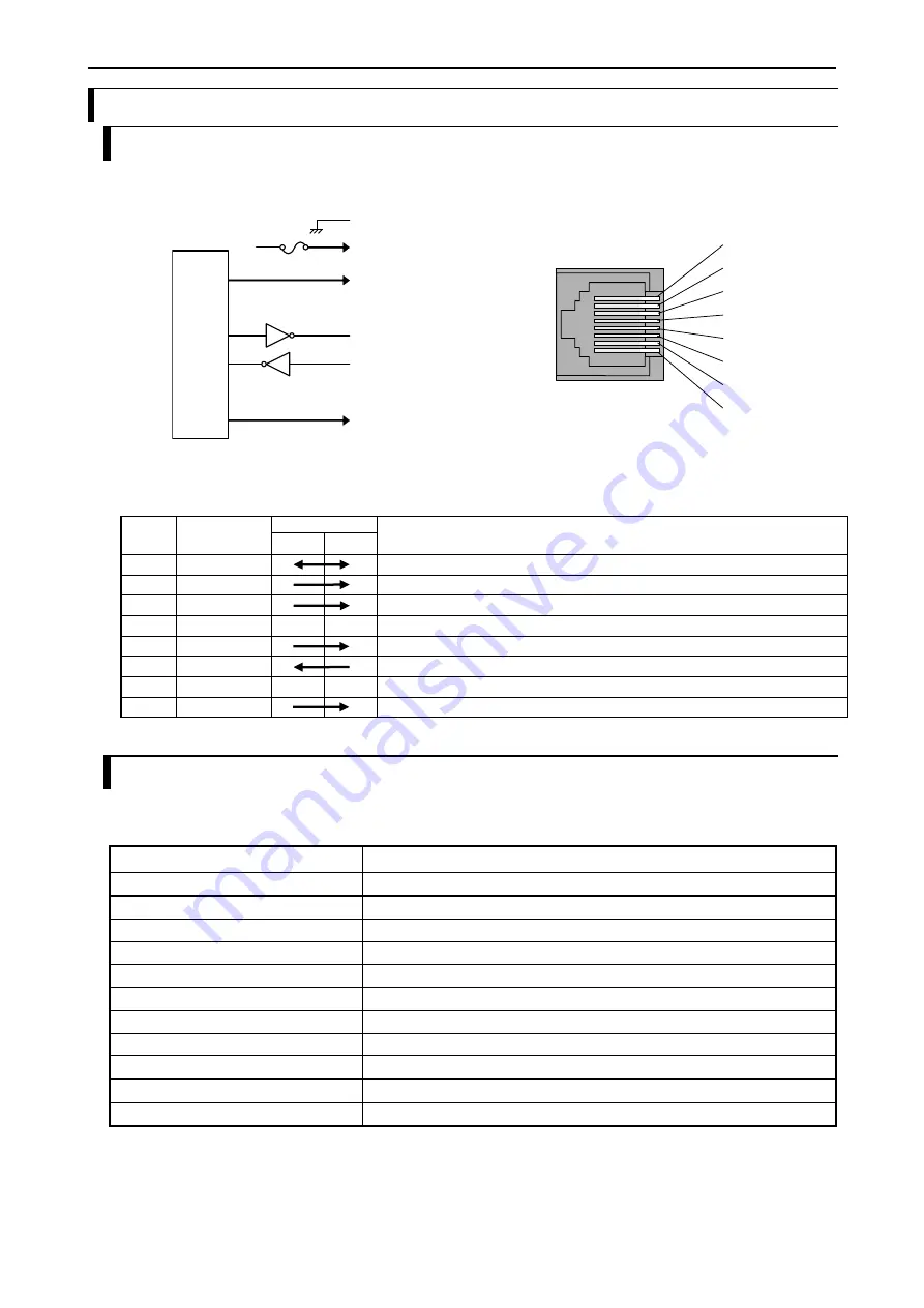
2.9.1 Physical layer interface
[1] SG
[4] N.C
[5] SD1(TxD)
[6] RD1(RxD)
[7] N.C
[8] RS1(RTS)
5 VDC
[2] VCC
[3] DTR1(ER)
M
ic
r
o
p
r
o
c
e
s
s
o
r
[2]
[3]
[4]
[5]
[6]
[7]
[8]
[1]
Figure 2.1 Circuit diagram and Pin No. of RS-232C
Table 2.7 List of signal of RS-232C
Pin
No.
Signal name
Direction
Meaning
PLC
Host
[1]
SG
Signal ground
[2]
VCC
5 V DC is supplied. (Protective fuse is connected.)
[3]
DTR1(ER)
When PLC is ready to communicate, this signal is high.
[4]
N.C
Don’t connect.
[5]
SD1(TxD)
Sending data from PLC
[6]
RD1(RxD)
Receiving data to PLC
[7]
N.C
Don’t connect.
[8]
RS1(RTS)
When PLC is ready to receive data, this signal is high.
2.9.2 RS-232C communication specifications
Specifications of RS-232C communication are shown in Table 2.8.
Table 2.8 RS-232C communication specifications
Item
Specifications
Transmission speed
4,800 bps / 9,600 bps / 19,200 bps / 38,400bps / 57,600bps / 115,200bps *
Interface
RS-232C
Maximum cable length
15 m
Connection mode
1 : 1
Synchronization method
Start-stop synchronization
Supported function
Modbus-RTU master/slave, General purpose communication
Transmission method
Serial transmission (bit serial transmission)
Transmission code outgoing sequence
Send out from the lowest bit in character
Error control
Vertical parity check, sum check, overrun check, framing check
Transmission unit
Message unit (variable length)
Maximum message length
1,024 bytes (including control characters)
*: Communication in 115.2kbps could be unstable depending on PC. If so, change the baud rate to 57.6kbps or slower.
Summary of Contents for EH-A14EDR
Page 6: ...MEMO ...
Page 10: ...MEMO ...
Page 141: ...Chapter 3 Programming 3 81 Program ...
Page 166: ...Chapter 5 Maintenance 5 4 MEMO ...
Page 170: ...Appendix A1 4 MEMO ...


