Chapter 2 Specifications
2
– 42
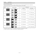
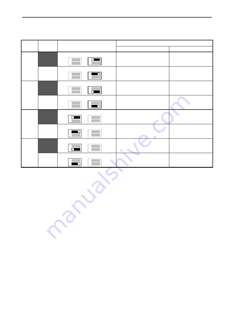
Setting of the DIP switches
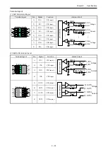
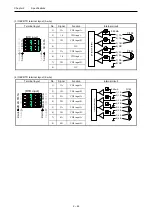
Voltage / current mode can be set for each channel of analog I/O. Be sure to make setting of DIP switches and setting by the
programming tool the same. In the case of not equal, the option board does not work properly.
*1: Be noted that setting ON is current mode for inputs while setting ON is voltage mode for outputs.
*2: All DIP switches are set voltage I/O mode at the time of shipment from factory.
Switch
No.
Setting
Figure of setting
Setting items
OBV-AIG
OBV-AIOG
SW1-1
OFF
1
2
SW2
ON
SW1
1
2
ON
IN1: Voltage input
IN1: Voltage input
ON
1
2
SW2
ON
SW1
1
2
ON
IN1: Current input
IN1: Current input
SW1-2
OFF
1
2
SW2
ON
SW1
1
2
ON
IN2: Voltage input
IN2: Voltage input
ON
1
2
SW2
ON
SW1
1
2
ON
IN2: Current input
IN2: Current input
SW2-1
OFF
1
2
SW2
ON
SW1
1
2
ON
IN3: Voltage input
OUT1: Current output *1
ON
1
2
SW2
ON
SW1
1
2
ON
IN3: Current input
OUT1: Voltage output *1
SW2-2
OFF
1
2
SW2
ON
SW1
1
2
ON
IN4: Voltage input
OUT2: Current output *1
ON
1
2
SW2
ON
SW1
1
2
ON
IN4: Current input
OUT2: Voltage output *1
Summary of Contents for EH-A14EDR
Page 6: ...MEMO ...
Page 10: ...MEMO ...
Page 141: ...Chapter 3 Programming 3 81 Program ...
Page 166: ...Chapter 5 Maintenance 5 4 MEMO ...
Page 170: ...Appendix A1 4 MEMO ...

