background image

4 – 1 

Chapter 4 Installation 

For use in safety, avoid installing the PLC in the following locations. 
 

- Excessive dusts, salty air, and/or conductive materials (iron powder, etc.) 
- Direct sunlight 
- Temperature less than 0

°

C or more than 55

°

- Dew condensation 
- Humidity less than 20% or more than 90% 
- Direct vibration and/or impact to the unit 
- Corrosive, explosive and/or combustible gasses 
- Water, chemicals and/or oil splashing on the PLC 
- Close to noise emission devices 


4.1 

Installation 


(1) Installing location and environment 

(a) Install the PLC in Use the environment specified in the “2.1 General Specifications”. 
(b) Mount the PLC onto the metal plate. 
(c) Install the PLC in a suitable enclosure such as a cabinet which opens with a key, tool, etc. 

(2) Installation of a base unit 

(a) Precaution when installing the base unit 

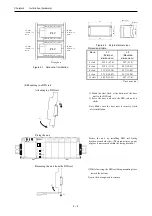
1] Fix the base unit securely with screws in 4 places (M4, length 20mm (0.79in.)or longer) or DIN rail. 
2] In order to keep within allowable ambient temperature range, 

a) Ensure sufficient space for air circulation. (50mm (1.97in.) or more at top and bottom, 10mm (0.39in.) 

or more at right and left) 

b)  Do  not  install  close  to  equipment  that  generates  a  lot  of  heat  (heater,  transformer,  large-capacity 

resistance, etc.). 

c)  If  ambient  temperature  is  more  than  55

°

C,  install  a  fan  or  a  cooler  so  that  the  ambient  temperature 

becomes below 55

°

C. 

3] Do not install inside a cabinet with high-voltage equipments installed. 
4] Install 200mm (7.87in.) or more away from high-voltage wires or power wires. 
5] Do not install the PLC upside down in vertical nor in horizontal. 


Summary of Contents for EHV+ Series

Page 1: ...HITACHI PROGRAMMABLE CONTROLLER APPLICATION MANUAL NJI 564B X IEC 61131 3 Compliant PLC ...

Page 2: ... covered If you have ant questions regarding the warranty please contact with your supplier or the local Hitachi Distributor Depending on failure part examination might be impossible Ordering parts or asking questions When contacting us for repair ordering parts or inquiring about other items please have the following details ready before contacting the place of purchase 1 Model 2 Manufacturing nu...

Page 3: ...umstances items marked with may result in major accidents In any case they both contain important information so please follow them closely Icons for prohibited items and required items are shown below Indicates prohibited items items that may not be performed For example when open flames are prohibited is shown Indicates required items items that must be performed For example when grounding must ...

Page 4: ...e terminals while the power is on There is a risk of electric shock Structure the emergency stop circuit interlock circuit etc outside the programmable controller hereinafter referred to as PLC Damage to the equipment or accidents may occur due to failure of the PLC However do not interlock the unit to external load via relay drive power supply of the relay output module CAUTION When performing pr...

Page 5: ...mble heat place in fire or short circuit the battery There is a risk of explosion or fire PROHIBITED Do not disassemble or modify the unit Electric shock malfunction or failure may result CAUTION Turn off the power supply before removing or attaching module unit Electric shock malfunction or failure may result ...

Page 6: ...scription of revision Date of revision Manual number 1 The first edition Jun 2010 NJI 564 X 2 Modbus TCP RTU and Global network variables added Sep 2010 NJI 564A X 3 NET framework V3 5 installation added Oct 2010 NJI 564B X ...

Page 7: ...9 2 High speed counter module EH CU CUE 2 72 2 9 3 Serial interface module EH SIO 2 77 2 9 4 PROFIBUS DP master module EH RMP 2 80 2 10 Accessories 2 82 2 10 1 Dummy module EH DUM 2 82 2 10 2 Expansion cable 2 82 2 10 3 Relay terminal block for 32 64 point module 2 83 2 10 4 Cable for 32 64 point module 2 85 2 10 5 Cable for EM H 200 series compatible 32 point module 2 86 2 10 6 Cable for counter ...

Page 8: ...ction 3 40 3 14 2 Port number setting 3 40 3 14 3 Modbus RTU master 3 41 3 14 4 General purpose communication 3 43 3 14 5 LED indication 3 43 3 14 6 Hardware reset and Software reset 3 43 3 15 Libraries 3 44 3 15 1 How to install 3 44 3 15 2 Real time clock 3 45 3 15 3 Serial communication 3 46 3 16 Troubleshooting 3 48 3 17 Version 3 52 Chapter 4 Installation 4 1 to 4 12 4 1 Installation 4 1 4 2 ...

Page 9: ...ea execute Reset origin in the first use after connecting a battery 1 2 Instruction Manuals I O modules and communication modules of EH 150 series are available with EHV series CPU as listed in page 2 2 Besides this application manual application manuals are available shown in Table 1 1 Table 1 1 Related manuals to EHV series CPU Product name Model Type Application manual number High functional mo...

Page 10: ...dule Converts external power to DC5V for CPU and I O modules through base unit 2 CPU module Reads input signals executes user application program and writes output signals 3 I O module Many types of I O modules are available such as digital input output modules analog input output modules high functional modules and communicate modules 4 Basic base unit All modules are mounted to base unit Basic a...

Page 11: ...e humidity 10 to 90 RH no condensation Vibration resistance Conforms to IEC 60068 2 6 Noise resistance Noise voltage 1 500 Vpp Noise pulse width 100 ns 1μs Noise input by a noise simulator across input terminals of a power module according to measuring method of Hitachi IES Based on IEC 61131 2 not applied for input modules Static noise 3 000 V at electrode part Insulation resistance 20 MΩ minimum...

Page 12: ...DC source type 3 DO 16 4 EH YT32 32 pts Transistor output 12 24V DC sink type 2 DO 32 4 EH YTP32 32 pts Transistor output 12 24V DC source type 2 DO 32 4 EH YT32E 32 pts Transistor output 12 24V DC sink type Spring type terminal DO 32 4 EH YTP32E 32 pts Transistor output 12 24V DC source type Spring type terminal DO 32 4 EH YT32H 32 pts Transistor output 5 12 24V DC sink type compatible connector ...

Page 13: ... CBM05W 32 64 point module cable both ends connector 5m EH CBM10W 32 64 point module cable both ends connector 10m EH CBM01 32 64 point module cable open and connector end 1m EH CBM03 32 64 point module cable open and connector end 3m EH CBM05 32 64 point module cable open and connector end 5m EH CBM10 32 64 point module cable open and connector end 10m CBM 02 EM H 200 compatible 32 point module c...

Page 14: ... STOP switch LED cover Front cover SD RD LINK RX Serial communication port Ethernet communication port Item Description RUN LED Indicates operation status Green lighting RUN off STOP ERR LED Indicates error status Red lighting Error Red blinking Battery error 7 segment LED Indicates error code Refer to section 3 16 for error code information E CLR button If any error occurs error code is displayed...

Page 15: ...cover Open this cover when operating the RUN switch or replacing the battery Keep the cover closed while the module is running When the cover is opened do not touch the printed wiring board Battery holder Battery Battery connector Battery Following data are maintained by battery 1 Data specified as VAR RETAIN and VAR PERSISTENT 2 RTC real time clock data Note Battery has polarity Check polarity in...

Page 16: ...ASE TX Gateway Modbus TCP client server Serial RS 232C 422 485 Gateway Modbus RTU master General purpose Switch Indications RUN LED ERR LED 7 segment LED 2 digit Indications RUN switch STOP RUN Remote STOP RUN enabled when the switch position is RUN E CLR button Reset error information Calendar Clock Support Built in RTC Battery LIBAT H for retentive data and Real time clock Maintenance function D...

Page 17: ...nd Pin No of RS 232C Table 2 6 List of signal of RS 232C Direction Pin No Signal name CPU Host Meaning 1 SG Signal ground 2 CD Carrier Detect signal 3 ER1 When CPU is ready to communicate this signal is high 4 ER2 Always high 5 SD Sending data from CPU 6 RD Receiving data to CPU 7 DR When this signal is high connected device is ready to communicate 8 RS When CPU is ready to receive data this signa...

Page 18: ...ound 2 N C Unused Do not connect 3 N C Unused Do not connect 4 TX Sending data from CPU 5 TXN Sending data from CPU 6 RXN Receiving data to CPU 7 RX Receiving data to CPU 8 N C Unused Do not connect CPU SG TX TXN RXN RX 1 2 3 4 5 6 7 8 CPU 1 2 3 4 5 6 7 8 SG TX TXN RXN RX Figure 2 3 RS 422 signal connection diagram A B External terminal block Twist pair cable CPU SG TX TXN RXN RX 1 2 3 4 5 6 7 8 C...

Page 19: ...se communication Modbus RTU master Transmission method Serial transmission bit serial transmission Transmission code outgoing sequence Send out from the lowest bit in character units Error control Vertical parity check sum check overrun check framing check Transmission unit Message unit variable length Maximum message length 1 024 bytes including control characters Caution 1 N communication RS 485...

Page 20: ...he AC power is supplied LED off indicates that the AC power is not supplied or output of DC power is short circuit LED blinking indicates that output current exceeds the limit DC power supply LED lighting indicates that the DC power is supplied LED off indicates that the DC power is not supplied or output of DC power is short circuit or overvoltage LED green Front cover Front cover set screw Open ...

Page 21: ...te at 750 V AC between DC output and FE Insulation resistance 20 MΩ minimum 500 V DC 1 Between AC input and FE 2 Between AC input and DC output Vibration resistance Conforms to JIS C 0911 16 7 Hz double amplitude 3 mm 0 12 in X Y Z each direction Conforms to JIS C 0040 10 to 57 Hz single amplitude 0 075 mm 57 to 150 Hz constant acceleration 9 8 m s2 Shock resistance Conforms to JIS C 0912 10G X Y ...

Page 22: ...minute at 1 500 V AC between DC input and FE Insulation resistance 20 MΩ minimum 500 V DC Between DC input and FE Insulation method Non insulation Terminal configuration Diagram of internal circuit 1 24 VDC 2 24 VDC Connect the input power 3 FE Connect to Class D grounding Connect with 24V DC because of supporting CE marking 1 2 3 Note Be sure to remove the connection between FE and 24V DC in the ...

Page 23: ...d I O modules via base unit CPU exchanges data with I O modules via base unit Select base unit according to the number of I O modules for your system Item Description Connector for power module This is a connector to power supply module Connector for CPU module This is a connector to CPU module or I O controller module Connector for I O module This is a connector to I O module Expansion cable conn...

Page 24: ... with the rotary switch Unit number must be ascending order from 1 to 5 Note Do not set any other number than 1 to 5 Although EH IOCH predecessor and EH IOCH2 can be used together do not use EH IOCH in the 5th expansion base EH IOCH2 must be used in 5th expansion base Rotary switch for Unit No This is a rotary switch for setting the unit No Please set 1 to 5 from the unit closer to the CPU module ...

Page 25: ... block 30 1 18 100 3 94 95 3 74 Name Description Terminal block The terminal block is to connect I O signals It is removable type M3 screws are used Use a crimping terminal fitting with screw diameter The maximum size of the cable is 0 75 mm2 Use 0 5 mm2 cable if using 2 crimping terminals in single terminal The recommended crimping terminal is indicated as below Terminal block cover This is a cov...

Page 26: ...ght EH YT32E YTP32E Approx 0 15kg 0 3lb Dimensions mm in LED display switch External wiring connector ON OFF 30 1 18 100 3 94 104 4 09 EH XD32H Approx 0 12kg 0 26lb Type Weight EH YT32H Approx 0 12kg 0 26lb Dimensions mm in LED display switch External wiring connector Compatible with EM H 200 series ON OFF 30 1 18 100 3 94 95 3 74 Name Specification LED display switch This is to switch I O groups ...

Page 27: ...3kg 0 29lb Dimensions mm in LED display switch External wiring connector SW2 SW1 30 1 18 100 3 94 95 3 74 Item Description LED display switch This is to switch I O groups to be displayed External wiring connector This is a connector for connecting I O signals Front view Indicated contents When signal status is ON LED lights up accordingly Displayed group can be selected by the LED display switch S...

Page 28: ... Input response OFFÎON 5ms maximum time ON ÎOFF 5ms maximum Insulation system Photo coupler insulation Input display Green LED External connection Removable type screw terminal block M3 Number of inputs common 8 Internal current consumption 30 mA maximum Terminal configuration No Signal name Diagram of Internal circuit 1 0 2 1 3 2 4 3 5 4 6 5 7 6 8 7 9 C 10 N C 11 N C 12 N C 13 N C 14 N C 15 N C 1...

Page 29: ...OFFÎON 5ms maximum time ON ÎOFF 5ms maximum Insulation system Photo coupler insulation Input display Green LED External connection Removable type screw terminal block M3 Number of inputs common 16 1 common 2 terminals Internal current consumption 50 mA maximum Terminal configuration No Signal name Diagram of Internal circuit 1 0 2 1 3 2 4 3 5 4 6 5 7 6 8 7 9 C 10 8 11 9 12 10 13 11 14 12 15 13 16 ...

Page 30: ...ÎON 16ms maximum time ON ÎOFF 16ms maximum Insulation system Photo coupler insulation Input display Green LED External connection Removable type screw terminal block M3 Number of input points commons 16 1 common 2 terminals Internal current consumption 50 mA maximum Terminal configuration No Signal name Diagram of internal circuit 1 0 2 1 3 2 4 3 5 4 6 5 7 6 8 7 9 C 10 8 11 9 12 10 13 11 14 12 15 ...

Page 31: ...response OFFÎON 15ms maximum time ON ÎOFF 25ms maximum Insulation system Photo coupler insulation Input display Green LED External connection Removable type screw terminal block M3 Number of inputs common 16 1 common 2 terminals Internal current consumption 50 mA maximum Terminal configuration No Signal name Diagram of Internal circuit 1 0 2 1 3 2 4 3 5 4 6 5 7 6 8 7 9 C 10 8 11 9 12 10 13 11 14 1...

Page 32: ...t response OFFÎON 15ms maximum time ON ÎOFF 25ms maximum Insulation system Photo coupler insulation Input display Green LED External connection Removable type screw terminal block M3 Number of inputs common 16 1 common 2 terminals Internal current consumption 50 mA maximum Terminal configuration No Signal name Diagram of Internal circuit 1 0 2 1 3 2 4 3 5 4 6 5 7 6 8 7 9 C 10 8 11 9 12 10 13 11 14...

Page 33: ... maximum Terminal configuration No Signal name No Signal name Diagram of Internal circuit 1 0 21 16 2 1 22 17 3 2 23 18 4 3 24 19 5 4 25 20 6 5 26 21 7 6 27 22 8 7 28 23 9 C 29 C 10 8 30 24 11 9 31 25 12 10 32 26 13 11 33 27 14 12 34 28 15 13 35 29 16 14 36 30 17 15 37 31 18 C 38 C 19 N C 39 N C 40 21 20 1 20 N C 40 N C 0 C 31 LED Internal circuit Applicable connectors 120mm 4 73in space is requir...

Page 34: ...mA maximum Terminal configuration No Signal name No Signal name Diagram of Internal circuit 1 0 21 16 2 1 22 17 3 2 23 18 4 3 24 19 5 4 25 20 6 5 26 21 7 6 27 22 8 7 28 23 9 C 29 C 10 8 30 24 11 9 31 25 12 10 32 26 13 11 33 27 14 12 34 28 15 13 35 29 16 14 36 30 17 15 37 31 18 C 38 C 19 N C 39 N C 40 21 20 1 20 N C 40 N C 0 C 31 LED Internal circuit Applicable connectors 120mm 4 73in space is requ...

Page 35: ...removable Number of inputs common 8 4 commons 8 terminals Internal current consumption 60 mA maximum Terminal configuration No Signal name No Signal name Diagram of Internal circuit 1 0 21 16 2 1 22 17 3 2 23 18 4 3 24 19 5 4 25 20 6 5 26 21 7 6 27 22 8 7 28 23 9 C1 29 C3 10 C1 30 C3 11 8 31 24 12 9 32 25 13 10 33 26 14 11 34 27 15 12 35 28 16 13 36 29 17 14 37 30 18 15 38 31 19 C2 39 C4 10 1 11 2...

Page 36: ...emovable type Number of inputs common 8 4 commons 8 terminals Internal current consumption 60 mA maximum Terminal configuration No Signal name No Signal name Diagram of Internal circuit 1 0 21 16 2 1 22 17 3 2 23 18 4 3 24 19 5 4 25 20 6 5 26 21 7 6 27 22 8 7 28 23 9 C1 29 C3 10 C1 30 C3 11 8 31 24 12 9 32 25 13 10 33 26 14 11 34 27 15 12 35 28 16 13 36 29 17 14 37 30 18 15 38 31 19 C2 39 C4 10 1 ...

Page 37: ...ximum Input response OFFÎON 4 ms maximum time ON ÎOFF 4 ms maximum Insulation method Photo coupler insulation Number of inputs common 32 1 common 4 terminals Input display LED red LED green Polarity Common terminal External connection Connector 50 pins Internal current consumption 20 mA maximum 60 mA maximum Specification of external wiring connector Product name Manufacturer Product No Connection...

Page 38: ...me No Signal name Diagram of Internal circuit 25 NC 50 NC 24 NC 49 NC 23 NC 48 NC 22 NC 47 NC 21 15 46 31 20 14 45 30 19 13 44 29 18 12 43 28 17 11 42 27 16 10 41 26 15 9 40 25 14 8 39 24 13 NC 38 NC 12 C 37 C 11 NC 36 NC 10 7 35 23 9 6 34 22 8 5 33 21 7 4 32 20 6 3 31 19 5 2 30 18 4 1 29 17 3 0 28 16 2 NC 27 NC 26 50 1 25 Note the direction of the connector 1 1 C 26 C EH XD32H This product 0 31 C...

Page 39: ... 33 62 49 2 1 22 17 43 34 63 50 3 2 23 18 44 35 64 51 4 3 24 19 45 36 65 52 5 4 25 20 46 37 66 53 6 5 26 21 47 38 67 54 7 6 27 22 48 39 68 55 8 7 28 23 49 C2 69 C2 9 C1 29 C1 50 40 70 56 10 8 30 24 51 41 71 57 11 9 31 25 52 42 72 58 12 10 32 26 53 43 73 59 13 11 33 27 54 44 74 60 14 12 34 28 55 45 75 61 15 13 35 29 56 46 76 62 16 14 36 30 57 47 77 63 17 15 37 31 58 C2 78 C2 18 C1 38 C1 59 N C 79 N...

Page 40: ...rew terminal block M3 Number of outputs common 8 Surge removal circuit Diode Fuse 2 4A 1 common External power supply for supplying power to S terminal 12 24V DC 10 15 30mA at the maximum Internal current consumption 30 mA maximum Short circuit protection function None 1 MFG No indicates production month 02F means June 2002 2 The fuse is not replaced by users Please contact your local supplier to ...

Page 41: ...e type screw terminal block M3 Number of outputs common 16 Surge removal circuit Diode Fuse 2 8A 1 common External connection for supplying power to S terminal 12 24V DC 10 15 30mA at the maximum Internal current consumption 50 mA maximum Short circuit protection function None 1 MFG No indicates production month 02F means June 2002 2 The fuse is not replaced by users Please contact your local supp...

Page 42: ...screw terminal block M3 Number of outputs common 8 Surge removal circuit Diode Fuse 2 4A 1 common External connection for supplying power to S terminal 12 24V DC 10 15 30mA at the maximum Internal current consumption 30 mA maximum Short circuit protection function None 1 MFG No indicates production month 02F means June 2002 2 The fuse is not replaced by users Please contact your local supplier to ...

Page 43: ...type screw terminal block M3 Number of outputs common 16 Surge removal circuit Diode Fuse 2 8A 1 common External connection for supplying power to S terminal 12 24V DC 10 15 30mA at the maximum Internal current consumption 50 mA maximum Short circuit protection function None 1 MFG No indicates production month 02F means June 2002 2 The fuse is not replaced by users Please contact your local suppli...

Page 44: ... Output display Green LED External connection Removable type screw terminal block M3 Number of outputs common 16 Surge removal circuit Built in Fuse None External connection for supplying power to S terminal 12 24V DC 10 15 30mA at the maximum Internal current consumption 50 mA maximum Short circuit protection function Available Terminal configuration No Signal name Diagram of Internal circuit 1 0...

Page 45: ...tion system Relay insulation Output display Green LED External connection Removable type screw terminal block M3 Number of outputs common 1 each output separated Surge removal circuit Varistor Varistor voltage 423 to 517V Fuse None External power supply Not necessary Internal current consumption 5V DC 220 mA maximum Terminal configuration No Signal name Diagram of Internal circuit 1 0 2 1 3 2 4 3 ...

Page 46: ...em Photo coupler insulation Output display Green LED External connection Removable type screw terminal block M3 Number of outputs common 12 1 common 2 terminals Surge removal circuit None Fuse None External power supply 24V DC 10 15 70mA at the maximum Internal current consumption 5V DC 40 mA maximum Terminal configuration No Signal name Diagram of Internal circuit 1 24V DC 2 N C 3 0 4 1 5 2 6 3 7...

Page 47: ... system Relay insulation Output display Green LED External connection Removal type screw terminal block M3 Number of output points commons 16 1 common 2 terminals Surge removal circuit None Fuse None External power supply Not used Internal current consumption 5V DC 430 mA maximum Terminal configuration No Signal name Diagram of Internal circuit 1 0 2 1 3 2 4 3 5 4 6 5 7 6 8 7 9 C 10 8 11 9 12 10 1...

Page 48: ...oupler triac insulation Output display Green LED External connection Removable type screw terminal block M3 Number of outputs common 4 Surge removal circuit Varistor Fuse 1 4A Internal current consumption 70 mA maximum 1 The fuse is not replaced by users Please contact your local supplier to repair Terminal configuration No Signal name Diagram of Internal circuit 1 0 2 N C 3 1 4 N C 5 2 6 N C 7 3 ...

Page 49: ...xternal connection Removable type screw terminal block M3 Number of output points commons 16 1 common 2 terminals Surge removal circuit Varistor Fuse 1 6 3A Be sure to install external fuse Internal current consumption 250 mA maximum 1 The fuse is not replaced by users Please contact your local supplier to repair Terminal configuration No Signal name Diagram of Internal output 1 0 2 1 3 2 4 3 5 4 ...

Page 50: ...ion Available 1 Total current of 4 common pins The maximum current for single common terminal is 3A 2 The fuse is not replaced by users Please contact your local supplier to repair Terminal configuration No Signal name No Signal name Diagram of Internal circuit 1 0 21 16 2 1 22 17 3 2 23 18 4 3 24 19 5 4 25 20 6 5 26 21 7 6 27 22 8 7 28 23 9 C 29 C 10 S 30 S 11 8 31 24 12 9 32 25 13 10 33 26 14 11...

Page 51: ...nction Available 1 Total current of 4 common pins The maximum current for single common terminal is 3A 2 The fuse is not replaced by users Please contact your local supplier to repair Terminal configuration No Signal name No Signal name Diagram of Internal circuit 1 0 21 16 2 1 22 17 3 2 23 18 4 3 24 19 5 4 25 20 6 5 26 21 7 6 27 22 8 7 28 23 9 C 29 C 10 S 30 S 11 8 31 24 12 9 32 25 13 10 33 26 14...

Page 52: ...S terminal 12 24V DC 10 15 30mA at the maximum Internal current consumption 5V DC 90 mA maximum Short circuit protection function Available 1 The fuse is not replaced by users Please contact your local supplier to repair Terminal configuration No Signal name No Signal name Diagram of Internal circuit 1 0 21 16 2 1 22 17 3 2 23 18 4 3 24 19 5 4 25 20 6 5 26 21 7 6 27 22 8 7 28 23 9 C1 29 C3 10 S1 3...

Page 53: ...o S terminal 12 24V DC 10 15 30mA at the maximum Internal current consumption 5V DC 90 mA maximum Short circuit protection function Available 1 The fuse is not replaced by users Please contact your local supplier to repair Terminal configuration No Signal name No Signal name Diagram of Internal circuit 1 0 21 16 2 1 22 17 3 2 23 18 4 3 24 19 5 4 25 20 6 5 26 21 7 6 27 22 8 7 28 23 9 C1 29 C3 10 S1...

Page 54: ...n Connector 50 pins Number outputs common 8 4 commons 4 terminals Surge removal circuit Diode Connecting case of the S terminal Fuse 1 1 5 A 1 common 2 A 1 common External power supply 2 For supplying power to the S terminal 5 to 27 V DC maximum 100 mA Internal current consumption 5 V DC 70 mA maximum 90 mA maximum Short circuit protection None 1 The fuse is not replaced by users Please contact yo...

Page 55: ...gnal name No Signal name Diagram of Internal circuit 25 NC 50 NC 24 NC 49 NC 23 NC 48 NC 22 NC 47 NC 21 15 46 31 20 14 45 30 19 13 44 29 18 12 43 28 17 11 42 27 16 10 41 26 15 9 40 25 14 8 39 24 13 S1 38 S3 12 C1 37 C3 11 NC 36 NC 10 7 35 23 9 6 34 22 8 5 33 21 7 4 32 20 6 3 31 19 5 2 30 18 4 1 29 17 3 0 28 16 2 S0 27 S2 26 50 1 25 Please note it in the direction of the connector 1 1 C0 26 C2 Inte...

Page 56: ...al configuration No Signal name No Signal name No Signal name No Signal name Diagram of Internal circuit 41 32 61 48 1 0 21 16 42 33 62 49 2 1 22 17 43 34 63 50 3 2 23 18 44 35 64 51 4 3 24 19 45 36 65 52 5 4 25 20 46 37 66 53 6 5 26 21 47 38 67 54 7 6 27 22 48 39 68 55 8 7 28 23 49 C2 69 C2 9 C1 29 C1 50 S2 70 S2 10 S1 30 S1 51 40 71 56 11 8 31 24 52 41 72 57 12 9 32 25 53 42 73 58 13 10 33 26 54...

Page 57: ...ir Terminal configuration No Signal name No Signal name No Signal name No Signal name Diagram of Internal circuit 41 32 61 48 1 0 21 16 42 33 62 49 2 1 22 17 43 34 63 50 3 2 23 18 44 35 64 51 4 3 24 19 45 36 65 52 5 4 25 20 46 37 66 53 6 5 26 21 47 38 67 54 7 6 27 22 48 39 68 55 8 7 28 23 49 C2 69 C2 9 C1 29 C1 50 S2 70 S2 10 S1 30 S1 51 40 71 56 11 8 31 24 52 41 72 57 12 9 32 25 53 42 73 58 13 10...

Page 58: ... block 30 1 18 100 3 94 95 3 74 Item Description Terminal block The terminal block is to connect I O signals It is removable type M3 screws are used Use a crimping terminal fitting with screw diameter The maximum size of the cable is 0 75 mm2 Use 0 5 mm2 cable if using 2 crimping terminals in single terminal The recommended crimping terminal is indicated as below Terminal block cover This is a cov...

Page 59: ...nnection Removable type screw terminal block M3 External power supply 24V DC 20 15 Approx 150mA Approx 400mA at power ON External wiring 2 core shield cable 20m 65 62ft maximum Internal current consumption 100mA maximum Terminal configuration No Signal name Diagram of Internal circuit 1 I0 2 I1 3 I2 4 I3 5 V4 6 V5 7 V6 8 V7 9 24 VDC 10 I0 11 I1 12 I2 13 I3 14 V4 15 V5 16 V6 17 V7 1 2 3 4 5 6 7 8 9...

Page 60: ... type screw terminal block M3 External power supply 24V DC 20 15 Approx 150mA Approx 400mA at power ON External wiring 2 core shield cable 20m 65 62ft maximum Internal current consumption 100mA maximum Terminal configuration No Signal name Diagram of Internal circuit 1 V0 2 V1 3 V2 4 V3 5 V4 6 V5 7 V6 8 V7 9 24 VDC 10 V0 11 V1 12 V2 13 V3 14 V4 15 V5 16 V6 17 V7 1 2 3 4 5 6 7 8 9 10 11 12 13 14 15...

Page 61: ...e screw terminal block M3 External power supply 24V DC 20 15 Approx 150mA Approx 400mA at power ON External wiring 2 core shield cable 20m 65 62ft maximum Internal current consumption 100mA maximum Terminal configuration No Signal name Diagram of Internal circuit 1 V0 2 V1 3 V2 4 V3 5 V4 6 V5 7 V6 8 V7 9 24 VDC 10 V0 11 V1 12 V2 13 V3 14 V4 15 V5 16 V6 17 V7 1 2 3 4 5 6 7 8 9 10 11 12 13 14 15 16 ...

Page 62: ...ype screw terminal block M3 External power supply 24V DC 20 15 Approx 150mA Approx 400mA at power ON External wiring 2 core shield cable 20m 65 62ft maximum Internal current consumption 100mA maximum Terminal configuration No Signal name Diagram of Internal circuit 1 I0 2 I1 3 I2 4 I3 5 I4 6 I5 7 I6 8 I7 9 24 VDC 10 I0 11 I1 12 I2 13 I3 14 I4 15 I5 16 I6 17 I7 1 2 3 4 5 6 7 8 9 10 11 12 13 14 15 1...

Page 63: ...type screw terminal block M3 External power supply 24V DC 20 15 Approx 150mA Approx 400mA at power ON External wiring 2 core shield cable 20m 65 62ft maximum Internal current consumption 100mA maximum Terminal configuration No Signal name Diagram of Internal circuit 1 I0 2 I1 3 I2 4 I3 5 I4 6 I5 7 I6 8 I7 9 24 VDC 10 I0 11 I1 12 I2 13 I3 14 I4 15 I5 16 I6 17 I7 1 2 3 4 5 6 7 8 9 10 11 12 13 14 15 ...

Page 64: ...nnection Removable type screw terminal block M3 External power supply 24V DC 20 15 Approx 150mA Approx 500mA at power ON External wiring 2 core shield cable 20m 65 62ft maximum Internal current consumption 100mA maximum Terminal configuration No Signal name Diagram of Internal circuit 1 V0 2 V1 3 I2 4 I3 5 N C 6 N C 7 N C 8 N C 9 24 VDC 10 V0 11 V1 12 I2 13 I3 14 N C 15 N C 16 N C 17 N C 1 2 3 4 5...

Page 65: ...screw terminal block M3 External power supply 24V DC 20 15 Approx 150mA Approx 500mA at power ON External wiring 2 core shield cable 20m 65 62ft maximum Internal current consumption 100mA maximum Terminal configuration No Signal name Diagram of Internal circuit 1 V0 2 V1 3 N C 4 N C 5 N C 6 N C 7 N C 8 N C 9 24 VDC 10 V0 11 V1 12 N C 13 N C 14 N C 15 N C 16 N C 17 N C 1 2 3 4 5 6 7 8 9 10 11 12 13...

Page 66: ...rew terminal block M3 External power supply 24V DC 20 15 Approx 150mA Approx 500mA at power ON External wiring 2 core shield cable 20m 65 62ft maximum Internal current consumption 130mA maximum Terminal configuration No Signal name Diagram of Internal circuit 1 I0 2 I1 3 I2 4 I3 5 N C 6 N C 7 N C 8 N C 9 24 VDC 10 I0 11 I1 12 I2 13 I3 14 N C 15 N C 16 N C 17 N C 1 2 3 4 5 6 7 8 9 10 11 12 13 14 15...

Page 67: ...screw terminal block M3 External power supply 24V DC 20 15 Approx 150mA Approx 500mA at power ON External wiring 2 core shield cable 20m 65 62ft maximum Internal current consumption 100mA maximum Terminal configuration No Signal name Diagram of Internal circuit 1 V0 2 V1 3 V2 4 V3 5 N C 6 N C 7 N C 8 N C 9 24 VDC 10 V0 11 V1 12 V2 13 V3 14 N C 15 N C 16 N C 17 N C 1 2 3 4 5 6 7 8 9 10 11 12 13 14 ...

Page 68: ...w terminal block M3 External power supply 24V DC 20 15 Approx 150mA Approx 500mA at power ON External wiring 2 core shield cable 20m 65 62ft maximum Internal current consumption 100mA maximum Terminal configuration No Signal name Diagram of Internal circuit 1 V0 2 V1 3 V2 4 V3 5 N C 6 N C 7 N C 8 N C 9 24 VDC 10 V0 11 V1 12 V2 13 V3 14 N C 15 N C 16 N C 17 N C 1 2 3 4 5 6 7 8 9 10 11 12 13 14 15 1...

Page 69: ...ting switch configures I O range input filter and resolution mode Current voltage switch configures current or voltage Front view Indicating contents OK ANAROG IN EH AXH8M 0 1 2 3 4 5 6 7 OK LED ON the module is operating in normal condition 0 to 7 LED OFF analog signal is operating in normal condition EH AXH8M If analog signal is less than 2mA corresponding number LED flashes Valid only when 4 to...

Page 70: ... the step input Current 249 Ω Input impedance Voltage Differential 200kΩ Channel and Internal circuit Photo coupler insulation Insulation system Between channels No insulation External connection Removable type screw terminal block M3 External power supply 24V DC 20 15 Approx 40mA Approx 300mA at power ON External wiring 2 core shield cable 20m 65 62ft maximum Internal current consumption 70mA max...

Page 71: ...to 3 voltage input for ch 4 to 7 OFF ON voltage input for ch 0 to 3 current input for ch 4 to 7 ON ON current input for ch 0 to 7 Highlighted part is factory default setting Note Be sure to set dip switches before use The dip switches must be set while power off otherwise setting status is not updated When the input range is changed be sure to set current voltage switch accordingly 5 10 V 3FFFH 16...

Page 72: ... 18ms maximum 90 arriving time after setting Current 400Ω maximum Output impedance Voltage 10kΩ minimum Channel and Internal circuit Photo coupler insulation Insulation system Between channels No insulation External connection Removable type screw terminal block M3 External power supply 24V DC 20 15 Approx 150mA Approx 400mA at power ON External wiring 2 core shield cable 20m 65 62ft maximum Inter...

Page 73: ... is valid Output filter Invalid Output filter Valid Highlighted part is factory default setting Note Be sure to set dip switches before use The dip switches must be set while power off otherwise setting status is not updated When the input range is changed be sure to set current voltage switch accordingly Resolution 1mV 0 to 10 V DC 10 V 3FFFH 16383 2710H 10000 0 1FFFH 8191 1388H 5000 5 4 to 22 mA...

Page 74: ...als in single terminal The recommended crimping terminal is indicated as below Terminal block cover This is a covert for installing on the terminal block Selects RTD type and range according to your system Switch setup Resistance temperature detector Measuring temperature range 1 2 3 4 5 6 7 8 Pt100 20 to 40 C ON ON OFF OFF ON OFF OFF OFF Pt100 50 to 400 C OFF OFF ON OFF OFF ON OFF OFF Pt1000 50 t...

Page 75: ...ature conversion data is H7FFF External wiring resistance Total resistance of 4 channels 400Ω at the maximum Additional function Linearization Error detection 2 Data is H7FFF if measured value exceeds 51 C or 410 C Wire breakage processing Temperature conversion data is H7FFF Internal current consumption 160mA maximum 1 The accuracy indicates the value of 10 minutes after power up The value may be...

Page 76: ...mm2 cable if using 2 crimping terminals in single terminal The recommended crimping terminal is indicated as below Terminal block cover This is a covert for installing on the terminal block Select switch Selects thermocouple types and Celsius Fahrenheit etc Front view Indicating contents OK ANAROG IN EH AXH8M 0 1 2 3 4 5 6 7 OK LED ON the module is operating in normal condition 0 to 7 LED OFF anal...

Page 77: ...n Removable type screw terminal block M3 External power supply 24V DC 10 100mA at the maximum External wiring 3 Shield cable Internal current consumption 70mA maximum Error detection Over upper limit value Breaking wiring detection Data H7FFF corresponding number LED flashes Under lower limit value Data H8000 1 The sum of accuracy of each sensor and the cold junction temperature error is the overa...

Page 78: ...ction compensation Valid Internal cold junction compensation ON Cold junction compensation Invalid 7 OFF Always OFF Do not turn ON 8 System mode OFF Always OFF Do not turn ON Highlighted part is factory default setting Note Be sure to set dip switches before use The dip switches must be set while power off otherwise setting status is not updated When the input range is changed be sure to set curre...

Page 79: ...g output logic positive negative logic and whether external input signal is in or not Turn off the power and remove the module out of the base to change the setting Purpose Applied switch Bit 1 Bit 2 Explanation Choice of OFF OFF Clock pulse Direction signal output Positive logic pulse output method OFF ON Clock pulse Direction signal output Negative logic ON OFF CW CCW pulse output Positive logic...

Page 80: ...thod 1 Pulse chain CW CCW 2 Clock direction signal CK Direction DIP switch No 1 and No 2 set the choice of pulse output system and the switching of each positive and negative logic Positioning Pulse output procedure 1 Open collector output Photo coupler insulation 2 Line driver output Photo coupler insulation Homing function 1 Free home position 2 Low speed homing 3 High speed homing 1 4 High spee...

Page 81: ...pecify polarity Input Insulation system Photo coupler A Specifications of Positioner connector CN1 conforms to RS 422 Terminal configuration No Signal Signal name Diagram of Internal circuit 1 Do Driver output 2 Do Driver output 3 Ri Receiver input 4 Ri Receiver input 5 5 V DC 5 V 6 0 V GND 7 0 V GND 8 12 V DC 12 V 1 8 8 7 6 5 2 1 4 3 Positioner Internal circuit 12V GND 5V 5V GND B Specifications ...

Page 82: ...et dip switches while power off LED name Front view LED name Details Color PW Lighted when the power is ON and the module operates regularly Green ER Lighted when the hardware error of the module occurs Red 1A Lighted depending on ON OFF of the A phase input signal of Channel 1 Green 1B Lighted depending on ON OFF of the B phase input signal of Chnnale1 Green 1M Lighted depending on ON OFF of the ...

Page 83: ...e marker polarity Bit 4 ON 1 2 3 4 5 6 7 8 9 10 ON Channel 2 Detects the marker at the ON edge OFF Channel 1 Stops counting while the CPU module stops Bit 5 ON 1 2 3 4 5 6 7 8 9 10 ON Channel 1 Keeps counting while the CPU module stops OFF Channel 2 Stops counting while the CPU module stops Select counting operation during STOP Bit 6 ON 1 2 3 4 5 6 7 8 9 10 ON Channel 2 Keeps counting while the CP...

Page 84: ...45 to 125 when up 45 to 125 when down Minimum counter pulse width ON 4 μs OFF 4 μs Minimum marker pulse width 10 μs detected at ON edge External wiring method 30 pin connector External wiring Wired with twisted pair cables and batch shielded cables Output voltage 12 24 V DC 30 V DC at the maximum Load current 20 mA point at the maximum Output method Open collector output Minimum load current 1 mA ...

Page 85: ...se B Connects an open collector signal at using voltage input Connects polarity at using differential input 22 Vin M 7 Vin M Connects a 12 to 24V DC power supply at using voltage input 23 M 8 M Connects polarity at using differential input 24 M 9 M Marker Connects an open collector signal at using voltage input Connects polarity at using differential input 25 to 27 N C 10 to 12 N C Connect nothing...

Page 86: ...e B Connects an open collector signal at using voltage input Connects polarity at using differential input 22 N C 7 Vin M Connects to a 12 to 24V DC power supply at using voltage input 23 N C 8 M Connects polarity at using differential input 24 N C 9 M Marker Connects an open collector signal at using voltage input Connects polarity at using differential input 25 to 27 N C 10 to 12 N C Connect not...

Page 87: ...ame Details Color LNK Lights up in the simple data link mode Green WDE Lights up when microcomputer error serious error occurs Common to port 1 port 2 Red MDE Lights up when module error serious error occurs Common to port 1 port 2 Red CDE Lights up when error warning such as command error occurs Common to port 1 port 2 Red SD1 Flashes while data is transmitted from port 1 Green RD1 Flashes while ...

Page 88: ...2 Odd number OFF ON OFF 7 1 Even number OFF ON ON 7 1 Odd number ON OFF OFF 8 2 None ON OFF ON 8 1 None ON ON OFF 8 1 Even number ON ON ON 8 1 Odd number Select of I F of port 2 communication Only DIP Sw2 Bit 8 is used for selecting I F of port 2 RS 232C or RS 422 485 RS 422 485 is decided according to external wiring 8 ON 3 4 5 6 7 2 1 Bit8 Select I F of Port 2 communication OFF RS 232C port ON R...

Page 89: ... 57 600 bps Transmission system Bit serial system Transmitted from the lowest bit of transmission signal Synchronization Asynchronous Transmission character configuration 20 21 22 23 24 25 26 27 Start bit Parity bit Including None Even Odd Stop bit 1 or 2 Transmission data 7 or 8 Input buffer 1 024 bytes port Output buffer 1 024 bytes port Error control Overrun error framing error parity error inp...

Page 90: ...utput data is cleared OFF ON FREEZE mode the output data is frozen ON OFF COPY mode the output data is coped from the CPU DIP switch 1 No 1 2 not used ON ON Not use Termination switch ON bus termination enabled OFF bus termination disabled Connector 2 Connect to field bus 9pin female Sub D The screw is the terminal for functional earth 1 For setting of this switch remove the module from the rack I...

Page 91: ... kbps 1200 m 19 2 kbps 1200 m 93 75 kbps 1200m 187 5 kbps 1000m 500 kbps 400m 1500 kbps 200m 3 Mbps 100m 6 Mbps 100m 12 Mbps 100m Self diagnosis System ROM RAM check watch dog timer check GSD file File name Hms_1004 gsd This file can either be downloaded from the webpage http www hms se fbfiles htm or received by contacting HMS Fieldbus AB Configurator Please prepare the configurator from HMS Fiel...

Page 92: ...odule is used for protecting the un mounted slot 2 10 2 Expansion cable Features Type EH CB5A 10A 20A Weight Approx 0 21 0 46 0 24 0 53 0 30 kg 0 66 lb Length 0 5 1 64 1 0 3 28 2 0 m 6 56 ft Function Connects to the expansion cable connector of the base unit and to the connector of the I O controller There is no directivity in the cable Either connector can be connected to the base side ...

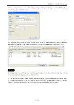
Page 93: ...5 is necessary to be installed for EHV CoDeSys If it is not installed the installation of EHV CoDeSys stops and message appears as right window Click Install to download over the Internet If it s not possible to access the Internet click cancel and install from the CD of EHV CoDeSys Full package of NET framework V3 5 service pack 1 is included in the CD ...

Page 94: ... to CPU module 2 Popup window appears at right bottom of screen Click the popup window 3 Click Install from a list or specific location Advanced and Next button 4 Click Include this location in the search with the path C Program Files EHV CoDeSys GatewayPLC Driver and Next button ...

Page 95: ...Chapter 3 Programming 3 3 5 USB driver installation is in progress 6 USB driver installation has been completed Click Finish to close the wizard ...

Page 96: ...tup In the first use you need to specify the type of development activity Standard or Professional you engage in the most This setting can be changed at any time in the menu Tools Options Features as below Click Predefined feature sets ...

Page 97: ...ears as below Choose Standard project enter new file name specify location and click OK Choose CPU type and programming language and click OK Available languages are as follows Continuous Function Chart CFC Function Block Diagram FBD Instruction List IL Ladder Logic Diagram LD Sequential Function Chart SFC Structured Text ST ...

Page 98: ...shot of EHV CoDeSys is shown below In the default setting Device tree is behind the POU window Click Devices tab to show it Toolbox and Properties windows can be shown by View menu Editor Variable declaration Device Toolbox Properties Messages ...

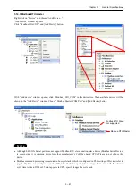
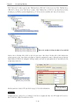
Page 99: ...configuration Right click on Empty slot and choose Plug Device Choose I O module for each slot The next slot can be configured by clicking next empty slot without closing the Plug Device window every time Module name can be renamed at Properties in right mouse click menu ...

Page 100: ...4H 4I 1 EH AYH8M 8 Analog output EH CU CUE EH CU E EH POS EH POS 4 EH RMP EH RMP EH SIO EH SIO 1 Although the number of channel is not 8 configure 8 ch Analog output 3 3 2 Scan For Devices Instead of plugging I O modules one by one actual information can be read out from connected CPU Right click on basic or expansion base and choose Scan For Devices Then Scan Devices dialog appears Click Copy all...

Page 101: ...gramming 3 9 3 3 3 Expansion unit Instead of Plug Device choose Add Device to configure expansion units EHV CPU1025 to CPU1102 allows to expand up to 5 expansion bases The low end type EHV CPU1006 is not expandable ...

Page 102: ... size of slave units N o t e Any types of slave units are available for EH RMP but only digital input 16 and digital output 16 module can be configured under EH RMP in EHV CoDeSys Configure those modules according to total input and output size For example if the total input and output size of slave modules are 4 and 8 words configure 4 times of Digital Input 16 R and 8 times of Digital Output 16 ...

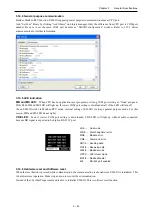
Page 103: ...l variable Double click on plugged I O module or right click and choose Edit Object I O Bus Mapping window appears as below Due to Motorola type byte order of SH 2 processor IEC address of 16 bit data starts from 1 0 and ends to 0 7 as follows Since the bit number shown at Channel corresponds to actual signal number put variable names according to the bit number ...

Page 104: ... system After defining variable names they will be automatically listed up when it is used in all POU with assist of auto complete If a variable is already used declared in POU or global variable list it can be taken by clicking icon in I O mapping window icon appears by clicking empty field ...

Page 105: ...used in the first time Auto Declare window will appear as below In this window there is the input field Address Enter I O address in this field according to data types If it is remained as blank the variable will be mapped in memory area After clicking OK button declared information is added automatically as below Declaration field ...

Page 106: ...it 14 QX6 6 Bit 15 QX6 7 QB6 QW3 Bit 16 QX5 0 Bit 17 QX5 1 Bit 18 QX5 2 Bit 19 QX5 3 Bit 20 QX5 4 Bit 21 QX5 5 Bit 22 QX5 6 Bit 23 QX5 7 QB5 Bit 24 QX4 0 Bit 25 QX4 1 Bit 26 QX4 2 Bit 27 QX4 3 Bit 28 QX4 4 Bit 29 QX4 5 Bit 30 QX4 6 Bit 31 QX4 7 QB4 QW2 QD1 Bit 32 QX3 0 Bit 39 QX3 7 QB3 Bit 40 QX2 0 Bit 47 QX2 7 QB2 QW1 Bit 48 QX1 0 Bit 55 QX1 7 QB1 Bit 56 QX0 0 Bit 63 QX0 7 QB0 QW0 QD0 QL0 LSB MSB...

Page 107: ... program You might determine the outputs behaviour by a program available within the project Enter the name of this program here and it will be executed when the PLC gets stopped Via button the input Assistant can be used for this purpose Update all variables in all devices If this option is activated then for all devices of the current PLC configuration all I O variables will get updated in each ...

Page 108: ...s means that default value configured in I O mapping table is ignored If default values need to be set set Reset all outputs in STOP as No In this case you must aware following limitation N o t e If Reset all outputs in STOP is No PLC outputs without IEC address such as counter outputs or pulse train outputs are NOT reset when CPU stops We recommend you to set Yes when using counter or positioning...

Page 109: ...shown below POU POU stands for Program Organization Unit This can be assumed as a paper to create your program Only one programming language can be used in one POU If you need another language add POU by right click on Application and choose Add object POU and choose language ...

Page 110: ...supports two tasks as below ApplicationStart This task is executed at once just after CPU starting ApplicationStop This task is executed at once just after CPU stopping Freewheeling task The task will be processed as soon as the program is started and at the end of one run will automatically restarted in a continuous loop There is no cycle time defined Be noted that the priority of this task is th...

Page 111: ...ress is remained as empty this variable will be assigned in a certain memory area of CPU Click OK button this variable is registered in declaration part of POU as below This variable is valid only in the POU Even if same variable name is used in another POU Auto Declare window will appear and it will be assigned in another memory location and handled as different variable ...

Page 112: ...d in all POUs Global Variable List must be created by right click on Application as below If new variable name is used in POU Auto Declare window appears as shown in local variables Choose VAR_GLOBAL at Scope as below New variable name test_input2 is registered in GVL as below instead of POU ...

Page 113: ...n downloading in the next time USB port USB port has only gateway function communication with EHV CoDeSys No configuration is necessary Serial port Function Gateway communication with EHV CoDeSys IEC programming Modbus RTU master or general purpose communication controlled by user program Configuration Serial port parameters are configured in Device window If the serial port is used for IEC progra...

Page 114: ...lick and choose Edit Object Device window will appear as below Choose Communication Settings tab and click Add gateway Gateway window will appear Click OK Sine the communication type between EHV CoDeSys and gateway in PC is TCP IP displayed driver name is TCP IP regardless of CPU s communication types ...

Page 115: ... it is displayed as below Click Set active path to choose as the target device N o t e Even if all Ethernet cable USB cable and serial cable are connected only the first detected device is shown If the filter is changed from Target ID to None all types of devices in the network are found Target CPU is activated Communication settings are completed ...

Page 116: ...e part to be corrected N o t e If unknown message appears it is recommended to Clean all in Build menu All compile information is deleted by this operation When all errors are removed as below click or choose Login in Online menu to download the program to CPU If no application is in the CPU this message appears Click Yes to download If unknown version of application is in the CPU this message app...

Page 117: ...atched red triangle icon is displayed at mismatched module as below Online change To change your program in running CPU online change you have to logout at first After program changing choose Login again You will have 3 options as below Login with online change Only incremental program is downloaded without CPU stop Login with download Whole the program is downloaded CPU is forced to stop Login wi...

Page 118: ...ime the application is copied from FLASH to RAM and executed automatically if RUN STOP switch is in RUN position Optional Timing to download boot application can be configured in Properties of Application Right click on Application of the project tree The default setting is shown below FLASH EHV CoDeSys Visualization Profile Referenced devices Referenced libraries CPU RAM Source Boot application C...

Page 119: ...ve original program file shown below as case b and c a Online change from PC with source file to CPU without source file Î Login b Online change from PC without source file to CPU with source file and DL info Î Source upload and Login c Online change from PC without source file to CPU with source file Î Source upload and Login then program download is required because EHV CoDeSys is not able to ve...

Page 120: ...d This exception status is cleared only by Reset operation EHV CoDeSys has 3 different types of Reset operation Reset warm Reset cold and Reset origin All of them can initialize exception status but behaviours of CPU are different as shown below Be noted that Reset origin initializes not only an exception but also your application and boot application in CPU module Operation VAR VAR RETAIN VAR PER...

Page 121: ...ronment setting How to configure Procedure of configuration is shown below with a simple project one CPU to send and the other CPU to receive Right click on the project and choose Add Device to add the 2nd CPU CPU Send Right click on Application of send CPU and choose Global Variable List Not Global Network Variable List Right click GVL and choose Properties Click Network properties tab and config...

Page 122: ...riables are sent only if their values have changed the Minimum gap can define a minimum time lapse between transfers Transmit on event Variables are sent while specified variable is TRUE Be noted that it is not edge detection but level detection Refer to online help of EHV CoDeSys for further information In this sample one global variable test_var is defined and one line program is written in POU ...

Page 123: ...mmunication path for Receive CPU and login download application You can see the variable test_var is counting up in the global network variable list in the Receive CPU N o t e If any parameters of global variable list is changed be sure to execute Clean or Clean All before login If more than 2 global variable lists are configured be sure to set another List identifier in ascending order Active Act...

Page 124: ...6 06 Write Single Register X X X 0x0F 15 Write Multiple Coils X X 0x10 16 Write Multiple Registers X X X 0x17 23 Read Write Multiple Registers X X X X Supported Not supported Modbus command processing is executed in bus cycle tack which is configured in PLC settings of Device as below You can specify any existing IEC tasks If the bus cycle task is unspecified task with the shortest cycle time is t...

Page 125: ...ernet in the device tree Then available devices will be shown in the Add Device window Click Modbus TCP master and Add Device button With Add device window opened click Modbus_TCP_master in the device tree Then Modbus TCP Slave is shown in the Add Device window Click Modbus TCP slave and Add Device button according to your Modbus system configuration e g if 3 slaves are to be controlled add 3 time...

Page 126: ... slave unit to open configuration window Set IP address response timeout and port number as below Unit ID is used when a Modbus gateway Ethenet to serial device is used Open Modbus Slave Channel tab and click Add Channel to add function codes Configure Be sure to configure all slave modules to be controlled ...

Page 127: ...of request to end of response per channel If several channels are used the sum of T1 T2 Tn is the minimum time to keep low or high the trigger bit But this is very approximate value and it is not easy to know T1 Recommended time would be 50 to 200ms or more depending on the number of channels If long size data is sent from CPU in low baud rate eg 255 byte in 2 400 bps takes about 1 second 25 error...

Page 128: ...on Ethernet and choose Add Device Click Modbus TCP Slave Device in the Add Device window and Add Device button Configure each parameter as below According to the size of Holding Registers and Input Registers data area will be assigned as seen in ModbusTCPSlave Device I O Mapping tab ...

Page 129: ...e device tree Then available devices will be shown in the Add Device window Choose Modbus Master COM Port and Add Device button N o t e Although CPU s Serial port does not support Modbus RTU slave function slave device Modbus Serial Device is available since it is common device for other manufacturer s CoDeSys based CPUs Please do not choose this device with EHV series CPUs Modbus RTU Slave Not su...

Page 130: ... Add Device button according to your Modbus system configuration e g if 3 slaves are to be controlled add 3 times of slave devices Function codes to be sent are configured in each slave Double click a slave unit to open configuration window Set slave address and response timeout Open Modbus Slave Channel tab and click Add Channel to add function codes Be sure to configure all slave modules to be c...

Page 131: ...ten to slave is assigned to output area QW N o t e When trigger type is set as Rising edge do not change the trigger bit too often otherwise rising edge could be missed Recommended timing is roughly calculated as follows T1 is the time from beginning of request to end of response per channel If several channels are used the sum of T1 T2 Tn is the minimum time to keep low or high the trigger bit Bu...

Page 132: ...nk X X Supported Not supported 3 14 2 Port number setting Open EH SIO Configuration window and set the port number from COM2 to COM15 COM1 is reserved for CPU local port or None Each COM port number must be unique If it is duplicated EH SIO does not work N o t e If a COM port of EH SIO is not used be sure to set None otherwise EH SIO doest not work CPU port COM1 fixed EH SIO port 1 COM2 to COM15 o...

Page 133: ...Although EH SIO s Serial port does not support Modbus RTU slave function slave device Modbus Serial Device is shown since it is common device for other manufacturer s CoDeSys based CPUs Please do not choose this device Modbus command processing is executed in bus cycle tack which is configured in PLC settings of Device refer to page 3 32 You can specify any existing IEC tasks If the bus cycle task...

Page 134: ...odbus_SIO_COM Configuration window appears Set the same COM port number as EH SIO configuration window Although baud rate and data frame format of EH SIO are configured with dip switches on board set same parameters as dip switches in this configuration window too Modbus operation is same as CPU port Refer to page 3 39 for further information N o t e In higher baud rate such as 57 6 or 115 2kbps i...

Page 135: ...turn off Even EH SIO works in Modbus RTU mode internal setting of EH SIO is always general purpose mode For this reason MB and MS LED do not light CDE LED Even if correct COM port setting is downloaded CDE LED will light up without cable connected because DR signal is expected to be high in RS 232C port 3 14 6 Hardware reset and Software reset When the reset button is pressed while communication t...

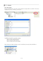
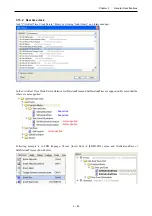
Page 136: ...necessary CmpHIESLib by choosing Add library as shown below CmpHIESLib is Hitachi IES s special library including Library for counter module EH CU CUE Library for positioning module EH POS Library for Profibus master module EH RMP If these libraries are not found in the library list as above install library by chooseing Tools Install library ...

Page 137: ...ary manager In the CAA Real Time Clock Extern libraries GetDateAndTime and SetDateAndTime are supported Be noted that the others are not supported Following example is in FBD language Choose Insert Box in FBD LD IL menu and GetDateAndTime or SetDateAndTime as shown below Supported Supported Not supported Not supported Not supported ...

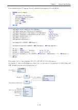
Page 138: ...ge of xExecute bit of GETDATEANDTIME current date and time is read out to the variable connected to dtDateAndTime as shown below When xExecute bit of GETDATEANDTIME is FALSE dtDateAndTime is default value 1970 1 1 0 0 0 3 15 3 Serial communication Add SysCom library by clicking Add library on Library manager Instead of SysCom library CAA SerialCom can be used but a sample program of SysCom library...

Page 139: ...est is 1 then string data 02 31 32 33 0D STX 123 CR will be sent out It is possible to write in FBD language as below but it is necessary to set parameters in COM_Settings and COM_SettingsEx as same as above program line 1 to 7 COM1 Non parity 1 stop bit baudrate 19 200bps buffer size 100 bytes Timeout 10ms 8 bit frame Connect 02 123 Connect 02 123 0d ...

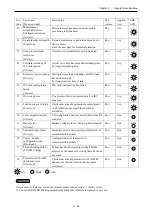
Page 140: ...ed when Description PLC system Applica tion ERR LED 88 Microprocessor failure Power on Overflow of internal watchdog timer due to system program error Stop Stop 11 System program error FLASH Power on Checksum value of system program Runtime in FLASH does not match the checksum calculated Stop Stop 12 System RAM failure Power on Read write check for system RAM has failed Stop Stop 13 Misalignment I...

Page 141: ...or of division command is 0 in IEC program Run Stop 31 Load boot project failed Power on Checksum value of application user program in FLASH does not match the checksum calculated Run Stop 70 I O configuration error Always I O configuration does not match with actual I O modules Run Run 71 Battery error Always Battery voltage is low or battery is disconnected Run Run Blink 72 Special module failur...

Page 142: ...r if application must start regardless of battery full or empty 21 error can be disabled as follows How to edit config cfg file 1 Open Device and click Files tab as below 2 After establishing communication set active path click update icon in the right field 3 The left field is inside of your PC Specify a folder to upload config file 4 Choose config cfg and click button 5 Go to specified folder at...

Page 143: ...ry install CmpHitachiErrors library by choosing Tools Install library Error code Libraries CmpHitachiErrors library Input Output all Last detected error code WORD all Execution bit to clear error code BOOL Result BOOL 70 FB 70 Error bit BOOL Unit number WORD Slot number WORD 71 71 Error bit BOOL 72 FB 72 Error bit BOOL Unit number WORD Slot number WORD 74 FB 74 Error bit BOOL Unit number WORD Slot...

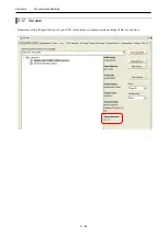
Page 144: ...Chapter 3 General Specifications 3 52 3 17 Version Firmware version Target Version of your CPU is monitored in communication settings of Device as below ...

Page 145: ...enclosure such as a cabinet which opens with a key tool etc 2 Installation of a base unit a Precaution when installing the base unit 1 Fix the base unit securely with screws in 4 places M4 length 20mm 0 79in or longer or DIN rail 2 In order to keep within allowable ambient temperature range a Ensure sufficient space for air circulation 50mm 1 97in or more at top and bottom 10mm 0 39in or more at r...

Page 146: ...11 11 11 11 12 12 12 12 13 13 13 13 14 14 14 14 15 15 15 15 0 0 0 0 1 1 1 1 2 2 2 2 3 3 3 3 4 4 4 4 5 5 5 5 6 6 6 6 7 7 7 7 8 8 8 8 9 9 9 9 10 10 10 10 11 11 11 11 12 12 12 12 13 13 13 13 14 14 14 14 15 15 15 15 0 0 0 0 1 1 1 1 2 2 2 2 3 3 3 3 4 4 4 4 5 5 5 5 6 6 6 6 7 7 7 7 8 8 8 8 9 9 9 9 10 10 10 10 11 11 11 11 SERIAL SERIAL SERIAL SERIAL ETHER ETHER ETHER ETHER NET NET NET NET EH EH EH EH 150 ...

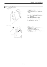
Page 147: ... module Note 2 Load the power module at the far left side of base unit Note 3 Load the CPU module and the I O controller to the left of the power module It can reinforce with the screw after installation Use M4 10mm screws in this case 2 Removing 2 1 3 1 Push in the lock button 2 With the lock button pushed in pull the top of the module toward the front 3 Raise it toward the top and pull it out No...

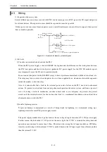
Page 148: ...oad etc The relay may turn on even when the power has not been supplied by an aluminum electrolytic capacitor inside the module to drive the relay Also it is conceivable that a fault in the external power and a failure in the PLC unit lead to abnormal actions To prevent such actions from causing abnormal operation the entire system and from a point of view of creating a fail safe mechanism constru...

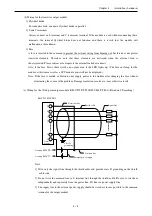
Page 149: ...e range of 0 49 to 0 78 N m when wiring d Use the same power supply system for the basic and expansion units 4 Wiring cable for I O signals A screw for all terminals is M3 Tighten within a torque range of 0 49 to 0 78 N m Use a crimp terminal with an outer diameter ot 6mm 0 24in or less when using it Use only up to 2 crimp terminals in the same terminal Avoid claming down more than 3 at the same t...

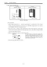
Page 150: ...xternal input contacts 2 For sensors such as a proximity switch and photoelectric switch current output type transistor open collector can be directly connected For voltage output type sensors connect them to the input terminal after first going through the transistor 3 Measures to prevent faulty contact in a strong electric contact Strong electric contact 3 W 560 Ω Approx 50mA 24V DC 0 C The curr...

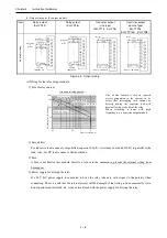
Page 151: ...e if the wiring route gets longer a phenomenon that voltage is generated on the input terminal though there is no signal actually because the leak current flows by the stray capacity between wirings may occur External device AC input module There are the following two methods 1 and 2 as measures Please limit the voltage caused by the electrostatic combination on the input terminal to half of the m...

Page 152: ... R load 240 V AC L load Switching life 10 000 times Shut off current A Life of the contact is also in squared reverse proportion to the current so be aware that interrupting rush current or directly driving the capacitor load will drastically reduce the life of the relay When switching is done with high frequency use a transistor output module 2 Surge killer For inductive load connect a surge kill...

Page 153: ...fuse out lamp for the module at this time as well as a CPU module error will not be displayed Note If the fuse is melted or blown do not supply power to the module after changing the fuse without eliminating the source of the problem Damage escalation smoke etc may otherwise result c Wiring for the 32 64 point output module EH YT32 YTP32 EH YT64 YTP64 Based on CE marking Note 1 Wire only the signa...

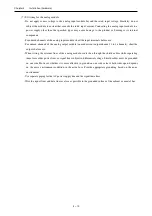
Page 154: ...alog output module unused current output channel 2 to 3 channels short the outputs before use When wiring the external lines of the analog module route then through the shield cables while separating them form other power lines or signal lines subject to differential voltage Shield cables must be grounded on one side However whether it is more effective to ground on one side or leave both sides op...

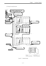
Page 155: ...se the same power supply system for basic and expansion bases Use a cable of about 14mm2 0 021 in2 Wiring for the power supply Class D grounding FE relay terminal block Use cable 0 75mm2 0 0011 in2 or less Leave a distance of 200mm 7 87in or more from the power line and do not have it running next to the power cable I O signal cable Always segregate power line I O signal and power supply cable Exp...

Page 156: ...Chapter 4 Installation hardware 4 12 MEMO ...

Page 157: ... next power up 2 Periodic inspection Turn off the power for the external I O circuit and check the following items once every six months Table 5 2 Items for periodic inspection Part Item Check criteria Remarks Programming device to CPU Check the operation of the programming device All switch and display lamps work properly Power supply Check for the voltage fluctuations 85 to 264 V AC Tester I O m...

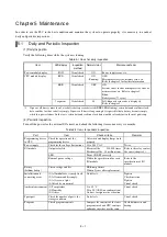
Page 158: ... years lifetime in case ambient temperature is 30 C For longer lifetime take account of installation location in terms of temperature and air circulation around power unit and 2 CPU module Some electrolytic capacitors are used in CPU module also I If lifetime of electrolytic capacitor is exceeded more errors could happen since noise resistance is not enough Be sure to overhaul CPU module periodica...

Page 159: ...ttery cable from CPU 5 Connect battery cable of new battery to CPU Red cable is to and black is to 6 Fold the excess lead wire and store it in the space for lead wire storage Otherwise the wire may be damaged by the front cover If replacing the battery without power supplied power off time should be less than 1 minute DANGER Precaution when handling the battery Use LIBAT H for the new battery Be c...

Page 160: ...Chapter 5 Maintenance 5 4 MEMO ...

Reviews: