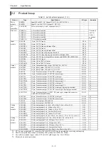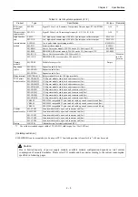
Chapter 2 Specifications
2 – 5
Table 2.3 Function specifications
Item Description
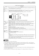
USB
communication
port
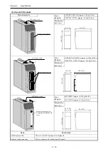
USB port supports gateway function (with EHV-CoDeSys) only. USB cable is not included with CPU package
nor supplied by Hitachi-IES. Use type-B USB cable.
Serial
communication
port
Serial port has both gateway function (with EHV-CoDeSys) and IEC programming function supporting
Modbus-RTU master and general purpose communication.
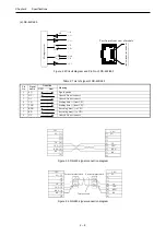
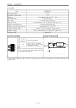
* Both a gateway / IEC programming function can be switched to RS-232C / RS-422 / RS-485.
[1] SG (
-
)
[2] CD (
Í
)
[3] ER1 (
Î
)
[4] ER2 (
Î
)
[5] SD (
Î
)
[6] RD (
Í
)
[7] DR (
Í
)
[8] RS (
Î
)
[1] SG (
-
)
[2] N.C.
[3] N.C.
[4] TX (
Î
)
[5] TXN (
Î
)
[6] RXN (
Í
)
[7] RX (
Í
)
[8] N.C.
RS-232C setting
RS-422 / 485 setting
Î
: PLC
Æ
Host
Í
: PLC
Å
Host
-
: PLC
ÅÆ
Host
[Note] Be noted that RD LED could light in a moment at power ON/OFF.
Ethernet
communicatio
n port
Ethernet port has both gateway function (with EHV-CoDeSys) and IEC programming function supporting
Modbus-TCP client/server.
In addition, network variables are transferred to/from other EHV+ CPUs over Ethernet network.
RUN / STOP
switch
When this switch position is in RUN, CPU start executing program. At the same time, remote controlling is
enabled, in which case, CPU is started or stopped by EHV-CoDeSys over communication.
When this switch position is in STOP. CPU stops executing program. In this status, remote controlling is
disabled.
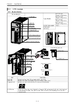
Lock button
Press this button to dismount.
Module can be fixed firmly by a screw of M4
×
10 mm(0.39in.).
Front cover
Open this cover when operating the RUN switch or replacing the battery.
Keep the cover closed while the module is running. When the cover is opened, do not touch the printed wiring
board.
Battery holder
Battery
Battery connector
[Battery]
Following data are maintained by battery.
(1) Data specified as VAR RETAIN and VAR PERSISTENT.
(2) RTC (real time clock) data
[Note]
- Battery has polarity. Check polarity in connecting the battery although opposite connection is mechanically
impossible.
- Be noted that the battery is not connected with factory default to prevent unnecessary battery consumption.
- When using the CPU module, check the battery and plug the battery connector to CPU as shown above.
- Refer to the table on page 5-2 for the life of battery.
Replace the battery every two years even when total power failure time is less than the guaranteed value.
!
Caution
Note the following matters for the communication port.
(1) Do not connect Ethernet cable to the serial port of CPU module. This could cause damage the CPU or connected equipment.
(2) In 100BASE-TX (100Mbps) communication of Ethernet, connection could be unstable due to external noise depending on cable
length, installation environment and etc. In this case, take following countermeasures.
1] Increase the number of times to retry in connected device.
2] Change Ethernet communication speed to 10Mbps.
(3) USB communication could be unstable under severe noise environment. Be sure to use short cable and route apart from power
line or other communication cables.
(4) Serial communication in 115.2kbps could be unstable depending on PC. If so, change the baud rate to 57.6kbps or slower.

