Chapter 4 Installation (hardware)
4 – 6
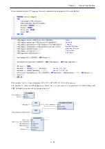
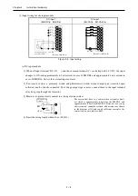
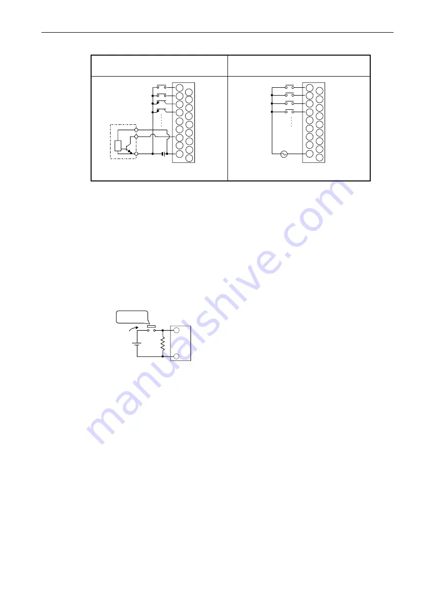
(5) Input wiring for the input module
DC input
(EH-XD16
、
EH-XD8)
AC input
(EH-XA16
、
EH-XAH16)
1
2
3
4
5
6
7
8
9
10
11
12
13
14
15
C
0
C
Current-output-type
proximity switch
24 V DC
(Example of EH-XD16)
+
1
2
3
4
5
6
7
8
9
10
11
12
13
14
15
C
0
C
AC100V
(Example of EH-XA16)
Figure 4.5 Input wiring
(a) DC input module
1] When all input terminal (X0, X1,
…
) and the common terminal (C) are loaded with 24 V DC, the input
changes to ON, and approximately 6.9 mA current in case of EH-XD8 and approximately 4 mA current in
case of EH-XD16, flow to the external input contacts.
2] For sensors such as a proximity switch and photoelectric switch, current-output-type (transistor open
collector) can be directly connected. For voltage-output-type sensors, connect them to the input terminal
after first going through the transistor.
3] Measures to prevent faulty contact in a strong electric contact
Strong electric
contact
3 W
560
Ω
Approx.
50mA
24V DC
+
0
C
The current that flows to a contact when external contacts
are closed is approximately 6.9mA for the EH-XD8, and
approximately 6.9mA for EH-XD16. If the use of a strong
electric contact cannot be avoided, add resistance as shown
in the diagram at left and supply sufficient current to the
contact to prevent a faulty contact.
4] Limit the wiring length within 30 m (98.43ft.).

