Chapter 4 Installation (hardware)
4 – 8
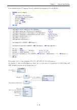
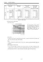
(6) Output wiring for the output module
Item
Relay output
(EH-YR12)
Relay output
(EH-YR16)
Transistor output
(sink type)
(EH-YT16
、
EH-YT8)
Transistor output
(source type)
(
EH-YTP16
、
EH-YTP16S
、
EH-YTP8
)
Ex
te
rn
al
w
iri
ng
+
-
NO
NO
0
6
1
7
2
8
3
9
4
10
5
11
C
C
FUSE
24 V DC
100/240 V AC
24 V DC +
Surge killer
or
Diaode
0
8
1
9
2
10
3
11
4444
12
5
13
6
14
7
15
C
C
FUSE
24 V DC
100/240 V AC
Surge killer
or
Diode
0
8
1
9
2
10
3
11
4
12
5
13
6
14
7
15
C
S
12/24 V DC FUSE
Diode
+
(Example of EH-YT16)
0
8
1
9
2
10
3
11
4
12
5
13
6
14
7
15
C
S
FUSE 12/24 V DC
Diode
+
(Example of EH-YTP16)
Figure 4.6 Output wiring
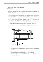
(a) Wiring for the relay output module
1] Life of relay contact
Life curve of relay contact
1000
500
100
10
1
0.1
0.5
1
2
24 V DC L load
24 V DC R load
240 V AC R load
240 V AC L load
Sw
itc
hi
ng
li
fe
(1
0,
00
0
tim
es
)
Shut-off current (A)
Life of the contact is also in squared
reverse proportion to the current, so be
aware that interrupting rush current or
directly driving the capacitor load will
drastically reduce the life of the relay.
When switching is done with high
frequency, use a transistor output module.
2] Surge killer
For inductive load, connect a surge killer (capacitor 0.1
µ
F, + resistance of around 100
Ω
) in parallel to the
load. Also, for DC load, connect a flywheel diode.
3] Fuse
A fuse is not built in this module. Install a 6A fuse in the common to prevent the external wiring from
burning out.
4] Power supply for driving the relay
If a 24 V DC power supply is connected to drive the relay, take care with respect to the polarity when
connecting. There is a risk that the internal circuit will be damaged if the wiring is done incorrectly. Also,
do not perform an interlock, etc. to the external load with the power supply for driving the relay.


