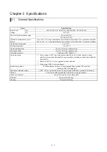
Chapter 2 Specifications
2 – 7
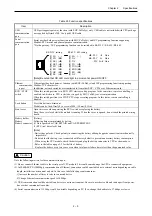
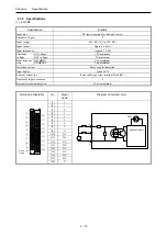
2.3.3 Serial port specifications
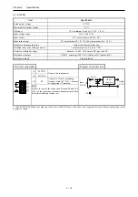
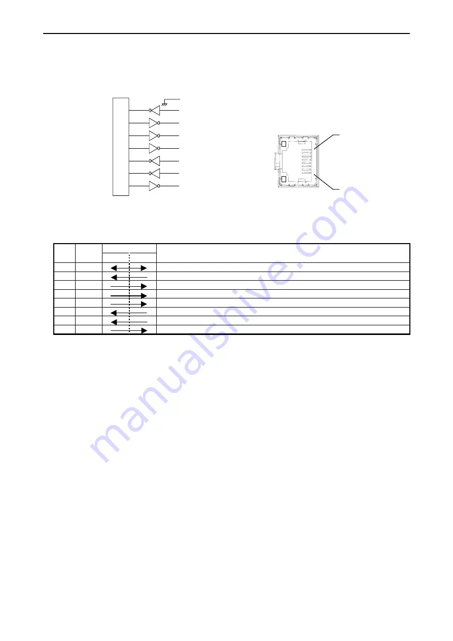
(1) RS-232C
[1]SG
[4]ER2
[5]SD
[6]RD
[7]DR1
[8]RS
[2]CD
[3]ER1
M
icrop
ro
ce
ssor
[1]
[2]
[3]
[4]
[5]
[6]
[7]
[8]
Port from a front view of module
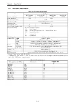
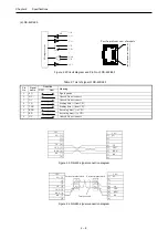
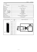
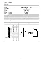
Figure 2.1 Circuit diagram and Pin No. of RS-232C
Table 2.6 List of signal of RS-232C
Direction
Pin
No.
Signal
name
CPU
Host
Meaning
1 SG
Signal
ground
2
CD
Carrier Detect signal.
3
ER1
When CPU is ready to communicate, this signal is high.
4 ER2
Always
high
5
SD
Sending data from CPU
6
RD
Receiving data to CPU
7
DR
When this signal is high, connected device is ready to communicate.
8
RS
When CPU is ready to receive data, this signal is high.


