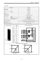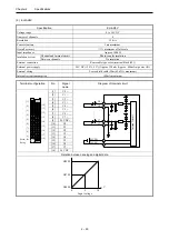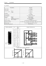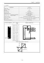
Chapter 2 Specifications
2 – 63
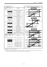
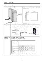
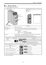
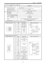
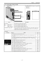
Setting switch
Support to analog data and digital data
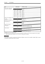
No. Setup
Function
1
2
Output range setting for ch.0 to 3
OFF
OFF
0 to 10 V DC
ON
OFF
OFF
ON
0 to 22 mA
1, 2
ON
ON
4 to 22 mA
3
4
Output range setting for ch.4 to 7
OFF
OFF
0 to 10 V DC
ON
OFF
OFF
ON
0 to 22 mA
3, 4
ON
ON
4 to 22 mA
5 Output
filter
OFF
Disable
5
ON Enable
6 Resolution
OFF
1/16384 (14 bits)
6
ON
1mV or 0.002mA
7 (System
mode)
7
OFF
Always OFF (Do not turn ON)
8 (System
mode)
8
OFF
Always OFF (Do not turn ON)
Current / voltage switch
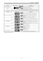
Reference) The images is as follows when the output filter is valid.
(Output filter: Invalid) (Output filter: Valid)
[Highlighted part is factory default setting.]
Note) Be sure to set dip switches before use. The dip switches must be set while power off, otherwise setting status is not updated.
When the input range is changed, be sure to set current / voltage switch accordingly.
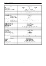
Resolution 1mV
0 to 10 V DC
10
V
3FFFH
(16383)
2710H
(10000)
0
1FFFH
(8191)
1388H
(5000)
5
4 to 22 mA
0 to 22 mA
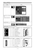
Current and voltage switch
4 to 7 channel
Current
Voltage
Current / voltage switch
0 to 3 channel
Current
Voltage
90
%
18ms or less
90
%
Approx. 200ms
Resolution 1/16384
10
20
mA
0
3A2EH
(14894)
2710H
(10000)
1D17H
(7447)
1388H
(5000)
Resolution 1/16384
Resolution
0.002mA
22
22
mA
0
10
4
38E3H
(14563)
1F40H
(8000)
1174H
(4468)
0FA0H
(3000)
F830H
(-2000)
Resolution 1/16384
Resolution
0.002mA
20

