ENGLISH
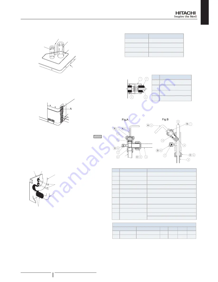
For the downward piping
Gas piping
Knock-out hole
Bottom base
Cables
Liquid piping
?
N O T E
Cables shall not contact directly to the pipes.
For the rear side piping
Rear Cover
?
N O T E
Remove the rear pipe cover under the rear cover and remove
part
following the slit.
6
Mount the piping cover in order to avoid water entering into
the unit. Seal the holes where pipes and wires are inserted,
by using a insulator and rubber bushes as shown below.
Piping
cover
Rubber bush (Accessory)
Add cross cutting to the center of the rubber bushing.
Attach rubber bushing to the hole of wiring.
In case that conduit tube is used, rubber bush is not
necessary.
Gas pipe
Power source and operating wiring
Liquid pipe
Insulation (Accessory).
Attach insulation to the pipe as shown in the figure and space shall not
exist at the piping hole.
Cut the insulation as shown in the figure when attaching work is difficult.
7
If the field-supplied piping is connected with stop valves
directly, it is recommended use a tube bender.
8
Check to ensure that the stop valves are closed completely
before connecting pipes.
9
Connect the field supplied refrigerant pipes to the indoor unit
and outdoor unit. Apply the oil thinly at the seat flare nut and
pipe before tightening.
The required tightening torque is as follows:
Pipe Size
Tightening Torque (Nm)
Ø 6.35 mm
20
Ø 9.52 mm
40
Ø 12.70 mm
60
Ø 15.88 mm
80
10
After connecting the refrigerant piping, seal the open space
between knockout hole and refrigerant pipes by using
insulation material.
Unit
side
Nº
Description
Insulation Material
Insulation Material
Field Supplied
Insulation Material
11
Operation of stop valve should be performed according to
the figure below.
Close before shipment
Nº
Description
Remarks
Cap
Allen wrench
Fig.A: Hex 4 mm / Fig.B: Hex. 8 mm
Refrigerant Piping
Field Supplied
Flare nut
Refrigerant pressure To Outdoor Unit
Seat Surface
Fully closed position
Check Joint
Only the charging those can be
connected
Cap
O-Ring
Rubber
Spindle valve
Open – Counterclockwise
Close – Clockwise
Tightening Torque (Nm)
Valve type
Model
A
B
C
D
Fig.A Liquid valve (4~6)HP
7-9
37
40
16
Fig.B Gas valve
(4~6)HP
9-11
30
60
9
REFRIGERANT PIPING & REFRIGERANT CHARGE
PMML0354A rev.1 - 03/2015
11


