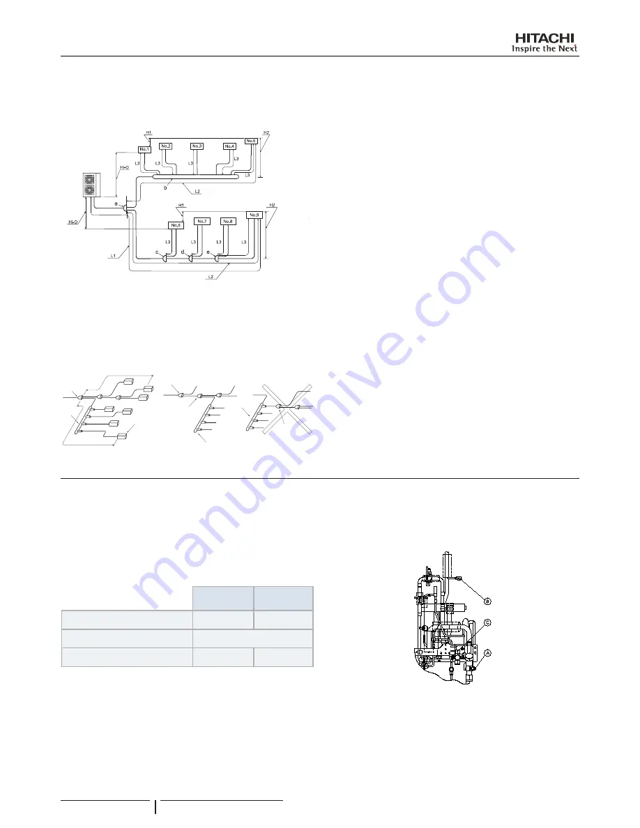
11.6.3 Combination branch piping system
Installation type
Considerations
It is possible to connect the header to the second branch, when
the first branch is also the line branch.
Do not connect a line branch to a header branch.
Header
Line
branch
Header
Indoor unit
Max. 40 m
Max. 40 m
Second branch
Line branch
(First branch)
Line branch
(First branch)
Header
11.6.4
Brazing work
!
C A U T I O N
•
Use nitrogen gas for blowing during pipe brazing. If oxygen, acetylene
or fluorocarbon gas is used, it will cause an explosion or poisonous
gas.
•
A lot of oxidation film will occur inside of tubes if no nitrogen gas blow
-
ing is performed during brazing work. This film will be flecked off after
operation and will circulate in the cycle, resulting in clogged expan
-
sion valves, etc. This will cause bad influence to the compressor.
•
Use a reducer valve when nitrogen gas blowing is performed during
brazing. The gas pressure should be maintained within 0.03 to 0.05
Mpa. If a excessively high pressure is applied to a pipe, it will cause
an explosion.
11.6.5 Refrigerant charge
!
C A U T I O N
•
Do not charge OXYGEN, ACETYLENE, or other flammable and poi
-
sonous gases into the refrigerant because an explosion can occur. It
is recommended that oxygen free nitrogen be charged for these types
of tests cycle when performing a leakage test or an airtight test. These
types of gases are extremely dangerous,
•
Insulate the unions and flare-nuts at the piping connection part com
-
pletely.
•
Insulate the liquid piping completely to avoid a decrease of perfor
-
mance; if not, it will cause sweating on the surface of the pipe.
•
Charge refrigerant correctly. Overcharging or insufficient charging
could cause a compressor failure.
•
Check for refrigerant leakage in detail. If a large refrigerant leakage
occurred, it would cause difficulty with breathing or harmful gases
would occur if a fire were being used in the room.
•
If the flare nut is tightened too hard, the flare nut may crack after a
long time and cause refrigerant leakage.
11.7 CAUTION OF THE PRESSURE BY CHECK JOINT
When the pressure is measured, use the check joint of gas stop
valve (A), and use the check joint of liquid piping (B) in the figure
below.
At that time, connect the pressure gauge according to the
following table because of high pressure side and low pressure
side changes by operation mode.
Cooling
operation
Heating
operation
Check joint for gas stop valve “A”
Low pressure
High pressure
Check joint for piping “B”
Exclusive for vacuum pump
Check joint for liquid stop valve “C”
High pressure
Low pressure
?
N O T E
Be careful that refrigerant and oil do not splash to the electrical parts at
removing the charge hoses.
REFRIGERANT PIPING & REFRIGERANT CHARGE
PMML0354A rev.1 - 03/2015
18


