background image

8

English

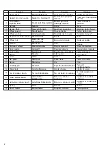
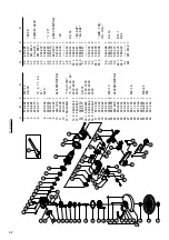
6. Service parts list

A: Item No.
B: Code No.
C: No. Used
D: Remarks

CAUTION

Repair, modification and inspection of Hitachi Power
Tools must be carried out by an Hitachi Authorized
Service Center.
This Parts List will be helpful if presented with the
tool to the Hitachi Authorized Service Center when
requesting repair or other maintenance.
In the operation and maintenance of power tools,
the safety regulations and standards prescribed in
each country must be observed.

MODIFICATIONS

Hitachi Power Tools are constantly being improved
and modified to incorporate the latest technological
advancements.
Accordingly, some parts (i.e. code numbers and/or
design) may be changed without prior notice.

NOTE

Due to HITACHI’s continuing program of research and
development, the specifications herein are subject to
change without prior notice.

IMPORTANT
Correct connection of the plug

The wires of the main lead are coloured in accordance
with the following code:

Blue: -Neutral
Brown: -Live

As the colours of the wires in the main lead of this tool
may not correspond with the coloured markings
identifying the terminals in your plug proceed as follows:
The wire coloured blue must be connected to the terminal
marked with the letter N or coloured black. The wire
coloured brown must be connected to the terminal mark-
ed with the letter L or coloured red. Neither core must be
connected to the earth terminal.

NOTE

This requirement is provided according to BRITISH
STANDARD 2769: 1984.
Therefore, the letter code and colour code may not
be applicable to other markets except The United
Kingdom.

Information concerning airborne noise and vibration

The measured values were determined according to
EN50144.

The typical A-weighted sound pressure level: 90 dB (A)
The typical A-weighted sound power level: 103 dB (A)

Wear ear protection.

The typical weighted root mean square acceleration
value does not exceed 2.5 m/s

2

.

Information about power supply system of nominal
voltage 230 V~ (For G18SE3, G18SG2, G23SC3,
G23SE2 only)

Under unfavorable mains conditions, this power tool may
cause 

transient voltage drops or interfering voltage

fluctuations.

This power tool is intended for the connection to a power
supply system with a maximum permissible system
impedance Z

MAX

 of 0.23 Ohm at the interface point (power

service box) of the user's supply.

The user has to ensure that this power tool is connected
only to a power supply system which fulfills the
requirement above.
If necessary, the user can ask the public power supply
company for the system impedance at the interface
point.

Summary of Contents for G 18SG2

Page 1: ...Lire soigneusement et bien assimiler ces instructions avant usage Prima dell uso leggere attentamente e comprendere queste istruzioni Deze gebruiksaanwijzing s v p voor gebruik zorgvuldig doorlezen Leer cuidadosamente y comprender estas instrucciones antes del uso Antes de usar leia com cuidado para assimilar estas instruçôes ιαβάστε προσεκτικά και κατανοήσετε αυτές τις οδηγίες πριν τη χρήση Handl...

Page 2: ...1 1 2 4 15 30 A B J a K 61 6 5 mm L 89 8 5 mm 22 5 mm a J I 3 5 K L N M 1 2 3 D C 4 B 6 7 8 9 0 7 A 9 5 H E G F ...

Page 3: ...hlebürste Gewöhnliche Kohlebürste Auto Stop Kohlebürste Feder Bürstenhalter Couvercle de charbon Douille pour poignée latérale Bouton poussoir blocage d arbre Arbre Aplats en couronne Couvre meule Rondelle de la meule Meule Ecrou de la meule Clef Disque diamant Poignée latérale Touche de verrouillage Interrupteur Levier Pièce fixée Vis Tige de positionnement Limite d usure No du balai en carbone B...

Page 4: ...oni Symbolen Hieronder staan symbolen afgebeeld die van toepassing zijn op deze machine U moet de betekenis hiervan begrijpen voor gebruik Símbolos A continuación se muestran los símbolos usados para la máquina Asegúrese de comprender su significado antes del uso Símbolos A seguir aparecem os símbolos utilizados pela máquina Assimile bem seus significados antes do uso Σύµβολα Τα παρακάτω δείχνουν ...

Page 5: ...n and free from oil and grease 15 Disconnect tools When not in use before servicing and when changing accessories such as blades bits and cutters 16 Remove adjusting keys and wrenches Form the habit of checking to see that keys and adjusting wrenches are removed from the tool before turning it on 17 Avoid unintentional starting Do not carry a plugged in tool with a finger on the switch Ensure swit...

Page 6: ...across flats of packing ground 䡬 Then turn the wheel guard to a desired position for use 䡬 Close the lever and fix it If and when required carry out adjustments by tightening or loosening the screw 䡬 If the lever does not move smoothly apply some lubricating oil to the sliding section between the set piece and the lever 䡬 Fasten the wheel guard at the position where the across flats of the wheel g...

Page 7: ...mbling Fig 1 1 Turn the machine upside down so that the spindle is facing upward 2 Mount the wheel washer onto the spindle 3 Fit the protruding part of the depressed center wheel or diamond wheel onto the wheel washer 4 Screw the wheel nut onto the spindle For diamond wheel assembling use the wheel nut with the convex side against the diamond wheel 5 Insert the push button to prevent rotation of t...

Page 8: ...e connected to the terminal marked with the letter N or coloured black The wire coloured brown must be connected to the terminal mark ed with the letter L or coloured red Neither core must be connected to the earth terminal NOTE This requirement is provided according to BRITISH STANDARD 2769 1984 Therefore the letter code and colour code may not be applicable to other markets except The United Kin...

Page 9: ... 321 546 1 31 321 545 1 32 306 887 1 M8 22 33 949 457 1 M8 34 321 544 1 A B C D 35 673 489 1 36 321 547 1 29 35 37 937 907Z 1 38 316 825 1 230MM A24R 39 937 909Z 1 40 320 218 1 41 306 890 1 42 320 223 1 7 20 43 320 216 1 44 600 0VV 1 6000VVCMPS2L 45 321 536 1 46 321 535 1 45 47 1 48 320 232 2 49 305 812 8 D4 16 50 1 999 061 2 50 2 999 061 1 EU SAF 50 3 999 089 1 EU SAF 51 320 231 1 52 1 53 320 233...

Page 10: ...uisición 4 Nombre y dirección del cliente 5 Nombre y dirección del distribudor Se ruega poner el sellú del distribudor con su nombre y dirección CERTIFICAT DE GARANTIE 1 No de modèle 2 No de série 3 Date d achat 4 Nom et adresse du client 5 Nom et adresse du revendeur Cachet portant le nom et l adresse du revendeur CETTIFICADO DE GARANTIA 1 Nùmero do modelo 2 Nùmero do série 3 Data de compra 4 Nom...

Page 11: ...48 1 2 3 4 5 ...

Page 12: ...0 EN55014 1 EN55014 2 EN61000 3 2 EN61000 3 3 και ή EN61000 3 11 σε συµφωνία µε τις Οδηγίες του Συµβουλίου 73 23 EOK 89 336 EOK και ή 98 37 EK Αυτή η δήλωση ισχύει στο προι ν µε το σηµάδι EC English EC DECLARATION OF CONFORMITY We declare under our sole responsibility that this product is in conformity with standards or standard ized documents EN50144 HD400 EN55014 1 EN55014 2 EN61000 3 2 EN61000 ...

Reviews: