background image

-10-

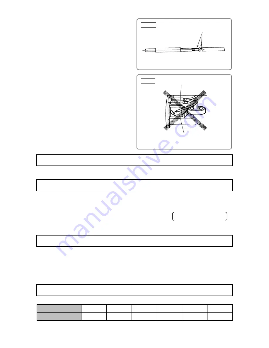
 Fig. 6    

Solderless connection

Tightening Torque

Adhesive Agent

Insulation Tests

No-Load Current Value

(3) When connecting the Earth Terminal 

[37]

 to

the internal wire (middle wire among three) of
the Noise Suppressor 

[38]

, strip off about 6

mm of the insulation sheath on the internal
wire, and then press-connect it together with
the Earth Terminal 

[37]

 with a clamping tool

available on the market.

(4) Confirm that the spring end does not hold the

pigtail when mounting the carbon brush. Do
not catch the pigtail in the tail cover when
mounting the tail cover.

• 

Hex. Socket Set Screw M4 x 4 

[16]

-------------------------- TB1406 (Synthetic rubber base)

• 

Tapping Screw D4 

[19][36][41]

------------------------------- 2.0 ± 0.5 N

m (20 ± 5 kgf

cm, 1.5 ± 0.4 ft-lbs)

• 

Seal Lock Screw (W/Sp. Washer) M4 x 10 

[11]

----------- 1.8 ± 0.5 N

m (18 ± 4 kgf

cm, 1.3 ± 0.3 ft-lbs)

• 

Tapping Screw (W/Sp. Washer) D5 x 30 

[6]

--------------- 2.9 ± 0.5 N

m (30 ± 5 kgf

cm, 2.2 ± 0.4 ft-lbs)

• 

Hex. Socket Set Screw M4 x 4 

[16]

---------------------------          0.5 N

m 5 

kgf

cm, 

 0.4 ft-lbs

0

0

0

• 

Bearing Lid (B) 

[2]

------------------------------------------------ 6.9 ± 0.5 N

m (70 ± 5 kgf

cm, 5.0 ± 0.4 ft-lbs)

Upon the completion of disassembly and repair, measure the insulation resistance and conduct a dielectric
strength test.

Insulation resistance: 10 M

 or more with DC 500 V megohm tester

Dielectric strength test: AC 4,400 V for 3 seconds, with no abnormalities ----------- 220 to 240 V products

AC 3,000 V for 3 seconds, with no abnormalities ----------- 110 to 127 V products

After no-load operation for 30 minutes, the no-load current value should be as follows:

Voltage (V)

110

120

127

220

230

240

Current (A) max.

4.9

4.7

4.0

2.5

2.4

2.3

Pigtail

Spring end

 Fig. 7

0.5 +

5 +

0.4 +

Summary of Contents for GP 2S2

Page 1: ...ations and performance as the GP 2 and is assembled at our production facility in Malaysia International Sales Division MARKETING OBJECTIVE PRODUCT NAME Hitachi Portable Grinder Model 25 mm 1 GP 2S2 Finishing of dies for press working die casting and molding Finishing of thread cutting dies tools and other small parts Internal grinding of tools and machine parts APPLICATIONS SELLING POINTS SPECIFI...

Page 2: ...m manual_view_export Throughout this TECHNICAL DATA AND SERVICE MANUAL a symbol s is are used in the place of company name s and model name s of our competitor s The symbol s utilized here is are as follows Competitors Symbols Utilized Company Name Model Name B BOSCH GGS27L 1215 for USA C MAKITA GD0601 ...

Page 3: ...H SIMILAR PRODUCTS 4 1 Comparison of Specifications 4 PRECAUTIONS ON SALES PROMOTION 5 1 Safety Instructions 5 2 Precautions Requiring Particular Attention during Sales Promotion 6 REPAIR GUIDE 7 1 Precautions on Disassembly and Reassembly 7 STANDARD REPAIR TIME UNIT SCHEDULES 12 Assembly Diagram for GP 2S2 ...

Page 4: ... 1 Powerful motor with high grinding speed Model GP 2S2 B C Power input 520 W 500 W 400 W Compact slim housing that is easy to grip SELLING POINTS 359 mm 14 1 8 ...

Page 5: ...itch Slide switch Enclosure Material Housing Glassfiber reinforced polyamide resin green Tail cover Glassfiber reinforced polyamide resin black Nose bracket Inner cover Aluminum alloy die casting Paint color Nose bracket Inner cover Metallic silver Net 1 7 kg 3 8 lbs without cord and wheel Weight Gross 2 5 kg 5 5 lbs Packaging Corrugated cardboard box Standard accessories Side handle 1 1 Wrench 17...

Page 6: ...023 KA 5 939104 KA 12 949021 KA 7 939106 KA 13 949022 2 For 3 mm shaft diameter Grit WA80P 20 pcs per package Type Code No Type Code No KA 20 939110 KC 20 939115 KA 21 939111 KC 21 939116 KA 22 939112 KC 22 939117 KA 23 939113 KC 23 939118 KA 24 939114 KC 24 939119 3 Collet Chuck Capacity Code No 3 mm 932624 6 mm 932627 8 mm 985135 1 8 985136 1 4 932666Z 4 Dresser Code No 939120 ...

Page 7: ...0 7 7 8 205 8 5 64 220 8 43 64 200 7 7 8 Weight 2 kg 1 7 3 8 lbs 1 75 3 9 lbs 1 6 3 5 lbs 1 6 3 5 lbs L mm 359 14 1 8 365 14 3 8 332 13 5 64 359 14 1 8 a mm 100 3 15 16 100 3 15 16 78 3 1 16 95 3 47 64 øD mm 35 1 3 8 35 1 3 8 38 1 1 2 43 1 11 16 Dimensions b mm 184 7 1 4 184 7 1 4 170 6 11 16 180 7 5 64 1 Depends on the market 2 Without cord and wheel COMPARISON WITH SIMILAR PRODUCTS L Overall len...

Page 8: ...ed in the Handling Instructions to enhance the safe and efficient use of the tool by the customer Salespersons must be thoroughly familiar with the Handling Instructions in order to offer appropriate guidance to the customer during sales promotion activities B Caution on Name Plate Each tool is provided with a Name Plate that contains the following basic safety precautions on the use of the tool F...

Page 9: ...re operation Operating the grinder with a damaged or cracked whetstone is very dangerous Please be sure to instruct the user to make a trial run by facing the whetstone away from any nearby person and confirm that there is no abnormality before operating the grinder The trial run time is as follows After replacing a whetstone At least 3 minutes Before starting operation At least 1 minute ...

Page 10: ...nd then push down the end of the Armature Ass y 17 shaft with a hand press to remove the Armature Ass y 17 2 Disassembly of Coupling The Coupling 10 may be difficult to remove from the Armature Ass y 17 due to rust if it cannot be removed by pulling by hand follow the procedure below 1 As illustrated in Fig 2 use a screwdriver or similar tool to slightly lift the Coupling 10 and partially remove i...

Page 11: ...24 moves to the ON position 3 Confirm that the Slide Knob 24 has not moved to the ON LOCK position and then push down on the Slide Knob 24 until it clicks while keeping the Slide Bar 32 raised 4 Raise the Slide Knob 24 straight up and remove it while keeping the Slide Bar 32 raised 6 Disassembly of the Spindle Loosen the Hex Socket Set Screw M4 x 4 16 and remove Bearing Lid B 2 The Spindle 3 can t...

Page 12: ...s connection and connect it to the Slide Switch 35 If the Noise Suppressor 38 is not used connect this internal wire to the Slide Switch 35 after clamping Tube D 39 with the solderless connection 2 Connect the four internal wires of Stator A 20 with the parts indicated in Fig 4 Connect the internal wires correctly as shown in Fig 5 a Choke coil and Noise Suppressor provided b Noise Suppressor not ...

Page 13: ... N m 20 5 kgf cm 1 5 0 4 ft lbs Seal Lock Screw W Sp Washer M4 x 10 11 1 8 0 5 N m 18 4 kgf cm 1 3 0 3 ft lbs Tapping Screw W Sp Washer D5 x 30 6 2 9 0 5 N m 30 5 kgf cm 2 2 0 4 ft lbs Hex Socket Set Screw M4 x 4 16 0 5 N m 5 kgf cm 0 4 ft lbs 0 0 0 Bearing Lid B 2 6 9 0 5 N m 70 5 kgf cm 5 0 0 4 ft lbs Upon the completion of disassembly and repair measure the insulation resistance and conduct a d...

Page 14: ... coil Black or White Black or White Slide Switch 35 2 1 4 3 Wiring Diagrams Wiring Diagrams Wiring Diagrams 1 For European countries Australia New Zealand South Africa and China 2 For other countries A Brown or Black Blue or White Cord 46 Black or White Black or White Stator A 20 Stator A 20 Black or White Black or White Slide Switch 35 2 1 4 3 ...

Page 15: ... Slide Switch Cord Tail Cover Carbon Brush x 2 Spindle Ball Bearing 6001VVCMPS2L Ball Bearing 6000VVCMPS2L Armature Ball Bearing 608VVC2PS2L Inner Cover Ball Bearing 608VVC2PS2L Bearing Cover Housing Stator A Slide Bar Nose Bracket Bearing Lid B STANDARD REPAIR TIME UNIT SCHEDULES ...

Page 16: ...odel GP 2S2 HAND GRINDER LIST NO F202 E1 2010 4 22 26 22 2 4 6 3 5 7 9 16 11 12 13 14 501 502 1 8 503 504 505 17 18 19 20 21 23 24 25 27 28 29 30 31 32 33 34 35 37 38 39 40 41 42 43 44 45 46 15 10 36 36 ...

Page 17: ...FAN GUIDE 1 19 982 021 HEX HD TAPPING SCREW D4 X 70 2 20 340 758C STATOR A 110V 120V 1 20 340 758G STATOR ASS Y A 110V 1 FOR GBR 110V 20 340 758M STATOR A 110V 1 FOR TPE 20 340 758E STATOR A 220V 230V 1 20 340 758H STATOR A 230V 1 FOR NZL 20 340 758F STATOR A 240V 1 20 340 758L STATOR A 240V 1 FOR AUS 21 315 877 DUST SEAL 1 22 608 VVM BALL BEARING 608VVC2PS2L 1 23 332 804 WASHER M14 1 24 314 428 S...

Page 18: ...CORD 1 CORD ARMOR D8 8 FOR GBR 110V 46 500 435Z CORD 1 CORD ARMOR D8 8 FOR GBR 230V HKG 46 323 974 CORD 1 CORD ARMOR D10 1 FOR UAE TPE 46 500 240Z CORD 1 CORD ARMOR D8 8 FOR USA CAN PAN 120V 46 500 237Z CORD 1 CORD ARMOR D8 8 FOR CHI 46 500 484Z CORD 1 CORD ARMOR D8 8 FOR ARG 46 500 439Z CORD 1 CORD ARMOR D8 8 FOR AUS NZL 46 500 455Z CORD 1 CORD ARMOR D8 8 FOR CHN PHI 46 500 423Z CORD 1 CORD ARMOR...

Page 19: ...AN MEX 607 949 021 MOUNTED WHEELS KA 12 D6 SHAFT 10 PCS 1 EXCEPT FOR USA CAN MEX 608 949 022 MOUNTED WHEELS KA 13 D6 SHAFT 10 PCS 1 EXCEPT FOR USA CAN MEX 609 939 110 MOUNTED WHEELS KA 20 D3 SHAFT 20 PCS 1 EXCEPT FOR USA CAN MEX 610 939 115 MOUNTED WHEELS KC 20 D3 SHAFT 20 PCS 1 EXCEPT FOR USA CAN MEX 611 939 117 MOUNTED WHEELS KC 22 D3 SHAFT 20 PCS 1 EXCEPT FOR USA CAN MEX 612 939 118 MOUNTED WHE...

Reviews: