GR4000 Quick Start Guide, Revision 1 - Preliminary
QSGGR4K00-10 5794047-1X
15
Procedure
3.
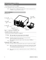
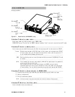
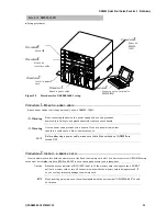
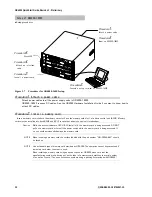
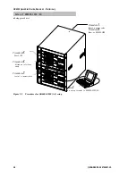
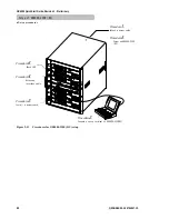
Connect a setup terminal to GR4000-160E2.
1.
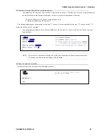
Connect a setup terminal to the CONSOLE port of BCU (BCU0) using a RS-232C cross cable.
2.
Start up a setup terminal.
3.
Start up communication software
NOTE
GR4000-160E2 is pre-configured in a way that a setup terminal can be connected to a
CONSOLE port of BCU0 when it is shipped from the factory. Connect a setup terminal to a
CONSOLE port of BCU0 in case that a basic control unit is redundant.
NOTE
As for the setup of communication software, see the communication software manual.
Procedure
4.
Attach an interface cable.
Attach an interface cable to a interface port.
Procedure
5.
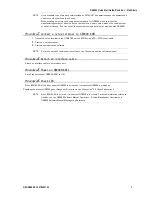
Power on GR4000-160E2.
Set all the breakers of GR4000-160E2 to ON. GR4000-160E2 has breakers on its backside
.
Procedure
6.
Check LED.
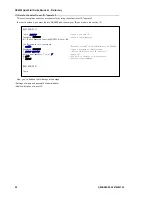
When BCU0 LED of the front panel of GR4000 is lit in green, it means that GR4000 is started up.
Regarding the process GR4000 goes through until it starts up, see the section “2.2 Other Preparations”.
NOTE
When BCU0 LED or BCU1 LED is lit in red, it means that GR4000 is in trouble. For detail
information related to troubles, see GR4000 Software Manual Operations - Device Management
Overview and GR4000 Software Manual Message Log Reference.
●
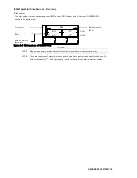
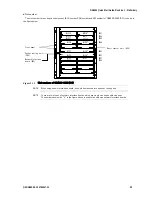
Slot number
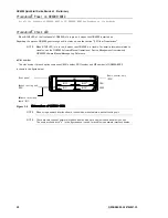
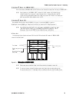
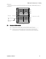
The slot number for each option component (BCU number, PRU number and NIF number) of GR4000-160E2
is shown in the figure below.
Figure 2-8
Slot numbers of GR4000-160E2
NOTE
When using a nework interface board, it should be mounted into a packet routing unit.
NOTE
There are two types of interface boards, which are single size and double size ones.
The number shown with “*” in the figure above is used for double size network interface boards.
BCU0
BCU1
NIF0
*
NIF2
*
NIF4
*
NIF6
*
NIF7
NIF5
NIF3
NIF1
Basic control unit
(BCU)
Front panel
Network interface
board (NIF)
Packet routing unit
(PRU)
PRU0
PRU1
PRU2
PRU3

