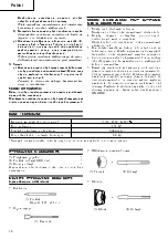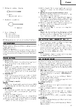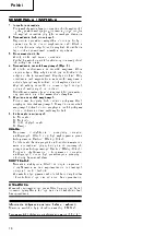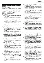
5
English
HOW TO USE THE DEM OLITION HAM M ER
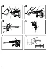
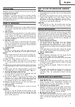
(Fig. 4)
1. After placing the tip of the tool on concrete surface,
sw itch ON.
2. By utilizing the w eight of the m achine and by firm ly
holding the ham m er w ith both hands, one can
effectively control the subsequent recoil m otion.
Proceed at a m oderate w ork-rate, the use of too
m uch force w ill im pair efficiency.
CAUTION
After long tim e of use, the cylinder case becom es
hot. Therefore, be careful not to burn your hands.
GREASE REPLACEM ENT
This m achine is of full air-tight construction to protect
against dust and to prevent lubricant leakage. This
m achine can be used w ithout grease supplem ent for an
extended period of tim e. How ever, perform the grease
replacem ent to m aintain the service life. Replace the
grease as described below .
1. Grease Replacement Period
You should look at the grease w hen you change
the carbon brush. (See item 4 in the section
M AINTENANCE AND INSPECTION.) Ask for grease
replacem ent at the nearest authorized Hitachi Service
Center.
In the case that you are forced to change the grease
by yourself, please follow the follow ing points.
2. How to replace grease
CAUTION:
Before replacing the grease, turn the pow er off and
pull out the plug from the receptacle.
(1) Rem ove the crank cover and w ipe off the old grease
inside. (Fig. 5)
(2) Supply 40 g (the standard volum e to cover the
connecting rod) of Hitachi Electric Ham m er Grease
A to the crank case.
(3) After replacing the grease, install the crank cover
securely.
NOTE:
The Hitachi Electric Ham m er Grease A is of the low
viscosity type. When the grease is consum ed,
p u r ch ase f r o m an au t h o r i zed Hi t ach i Ser v i ce
Center.
M AINTENANCE AND INSPECTION
1. Inspecting the tool
Since use of a dull tool w ill degrade efficiency and
cause possible m otor m alfunction, sharpen or
replace the tool as soon as abrasion is noted.
2. Inspecting the mounting screw s
Regularly inspect all m ounting screw s and ensure
that they are properly tightened. Should any of the
screw s be loose, retighten them im m ediately. Failure
to do so could result in serious hazard.
3. M aintenance of the motor
The m otor unit w inding is the very “ heart” of the
pow er tool. Exercise due care to ensure the w inding
does not becom e dam aged and/or w et w ith oil or
w ater.
APPLICATIONS
Breaking concrete, chipping off concrete, grooving, bar
cutting, and driving piles.
Application exam ples:
Instal l ati on of pi pi ng and w i r i ng, sani tar y faci l i ty
installation, m achinery installation, w ater supply and
drainage w ork, interior jobs, harbor facilities and other
civil engineering w ork.
PRIOR TO OPERATION
1. Pow er source
Ensure that the pow er source to be utilized conform s
to the pow er requirem ents specified on the product
nam eplate.
2. Pow er sw itch
Ensure that the pow er sw itch is in the OFF position.
If the plug is connected to a receptacle w hile the
pow er sw itch is in the ON position, the pow er tool
w ill start operating im m ediately, w hich could cause
a serious accident.
3. Extension cord
When the w ork area is rem oved from the pow er
source, use an extension cord of sufficient thickness
and rated capacity. The extension cord should be
kept as short as practicable.
4. Installing Tools
CAUTION
Be sure to sw itch pow er OFF and disconnect the
plug from the receptacle to avoid serious trouble.
NOTE:
When using tools such as bull points, cutters, etc.,
m ake sure to use the genuine parts designated by
our com pany.
(1) Clean the shank portion of the tool.
(2) As show n in Fig. 1, pull grip (A) in the direction
of
✁
, and insert the tool into a hole of the front
cap.
(3) Adjust the groove position w hile turning the tool,
and furtherm ore insert it until it hits the end of the
hole.
(4) Return grip (A) to its original position, pull the tool
and m ake sure it is locked com pletely. (Fig. 2)
5. Deciding Working Position of Tool
The tool can be turned every 30 degrees and can
be fixed at the position of 12 steps.
(1) As show n in Fig. 3, if the grip (A) is turned in the
direction of
✂
in a state w here the grip (B) is
pushed in the direction of
✁
, the blade angle can
be changed freely to any desired position.
(2) Release grip (B) and turn the tool, and m ake sure
that it is locked com pletely.
6. Removing Tool
As show n in Fig. 1, pull grip (A), and pull out the
tool.
CAUTION
Be sure to grip the handle and side handle or grip
(C) portion during w ork. Do not hold by the grip
(A) during w ork. If you pull it by m istake, the bull
point could jum p out.
Summary of Contents for H 45M R
Page 1: ...Отбойные молотки Hitachi H45MR NF H45MR Инструкция пользователя ...
Page 3: ...1 3 4 1 2 5 6 17 mm a a 43 6 mm 73 7 mm ...
Page 13: ...11 P P P P P q r s t P P q t r P t P P P q t P P t P P P q t P ...
Page 15: ...13 P q rst qs qst q rst q rst r ...
Page 16: ...14 P qr s r t qr s P qr s t t P P P r t P ...
Page 17: ...15 Polski P q r r r s t r r s r r r q s s s s q q s q s r s r s r q q ...
Page 19: ...17 Polski P P P qrst P P P P P P ...
Page 20: ...18 Polski P qr s t ...
Page 21: ... Magyar P P q r s q q q t q t q q q q q q q t q q q q q q q q t q t t q q q q q q q ...
Page 22: ... Magyar P 1 q rs t q q q r t q q q t q s q q q qq s ü Ó q q t q q s q q q q t q q s Ü ...
Page 23: ... Magyar P P q r s t q r P P P P P q r P P P P P P t P s P P P s P P P ...
Page 24: ... Magyar P ...
Page 28: ... P q rst ...
Page 29: ... P P P P P P P P P P P P P P P P P P P P P P P P P P P P P P P P P P P P P ...
Page 30: ... Ó Ó Ó Ö P P t P P P s t Ó Ó Ó qr q ...
Page 31: ... P P q r s s s s s ts t t r r s P P P q ...
Page 32: ... P ...
Page 33: ...31 P P q r s t s ...
Page 35: ...33 P P q r s t q q r r s s ...
Page 36: ...34 P P q rs t r r r P P P P P ...
Page 37: ...35 P ...
Page 38: ...36 ...
Page 40: ...38 ...
Page 42: ...40 ...
Page 43: ...41 ...
Page 44: ...42 ...


