-5-
(2) Removal of the piston
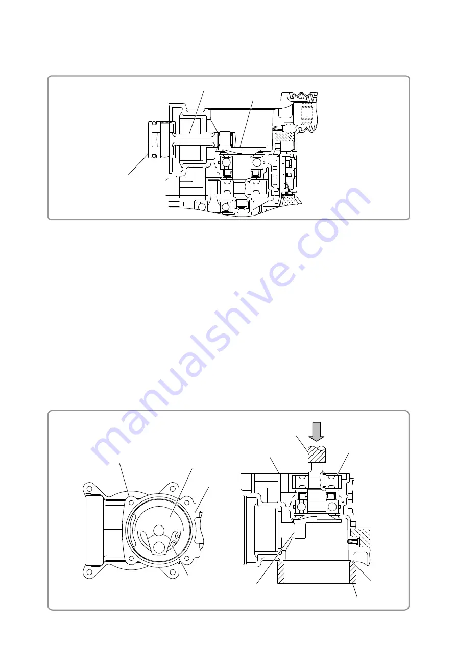
Move the Connecting Rod Ass'y
[42]{39}
as shown below and remove the Piston
[41]{38}
from the
Crank Shaft
[86]{83}
.
(3) Removal of the first gear and crank shaft
(a) Remove the Bolt M5 x 16
[65]{62}
, and then remove the Crank Cover
[84]{81}
from the Crank
Case
[91]{88}
.
(b) Remove the Bolt M5 x 16
[65]{62}
, Bolt M5 x 12
[56]{53}
, and Screw D5 x 25
[70]{67}
, and then
remove handle (A), handle (B), and Back Cover
[64]{61}
.
(c) Disconnect the connector of the Panel
[98]{95}
from the Controller
[53]{50}
. Remove the Bolt M6 x
45
[49]{46}
, and then remove the Crank Case
[91]{88}
from the Housing
[52]{49}
.
(d) Wipe off grease from the Piston
[41]{38}
side and the First Gear
[96]{93}
side in the Crank Case
[91]{88}
, and then use a retaining ring puller to remove the Retaining Ring for D40 Hole
[87]{84}
that retains the Ball Bearing 6203DD
[88]{85}
, while turning the Crank Shaft
[86]{83}
so that you
can see the Retaining Ring for D40 Hole
[87]{84}
hole.
(e) Place the Crank Case
[91]{88}
on an adequate cradle with its Crank Cover
[84]{81}
fixing surface
facing down, and then use a hand press to press down on the end surface of the Crank Shaft
[86]{83}
. Then remove the First Gear
[96]{93}
and Crank Shaft
[86]{83}
from the Crank Case
[91]{88}
.
Adequate cradle
Hand press
[42]{39}
[86]{83}
[41]{38}
[96]{93}
[91]{88}
[86]{83}
[91]{88}
[86]{83}
Crank cover
fixing surface
[87]{84}
Crank cover
fixing surface


