
--- 17 ---
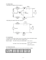
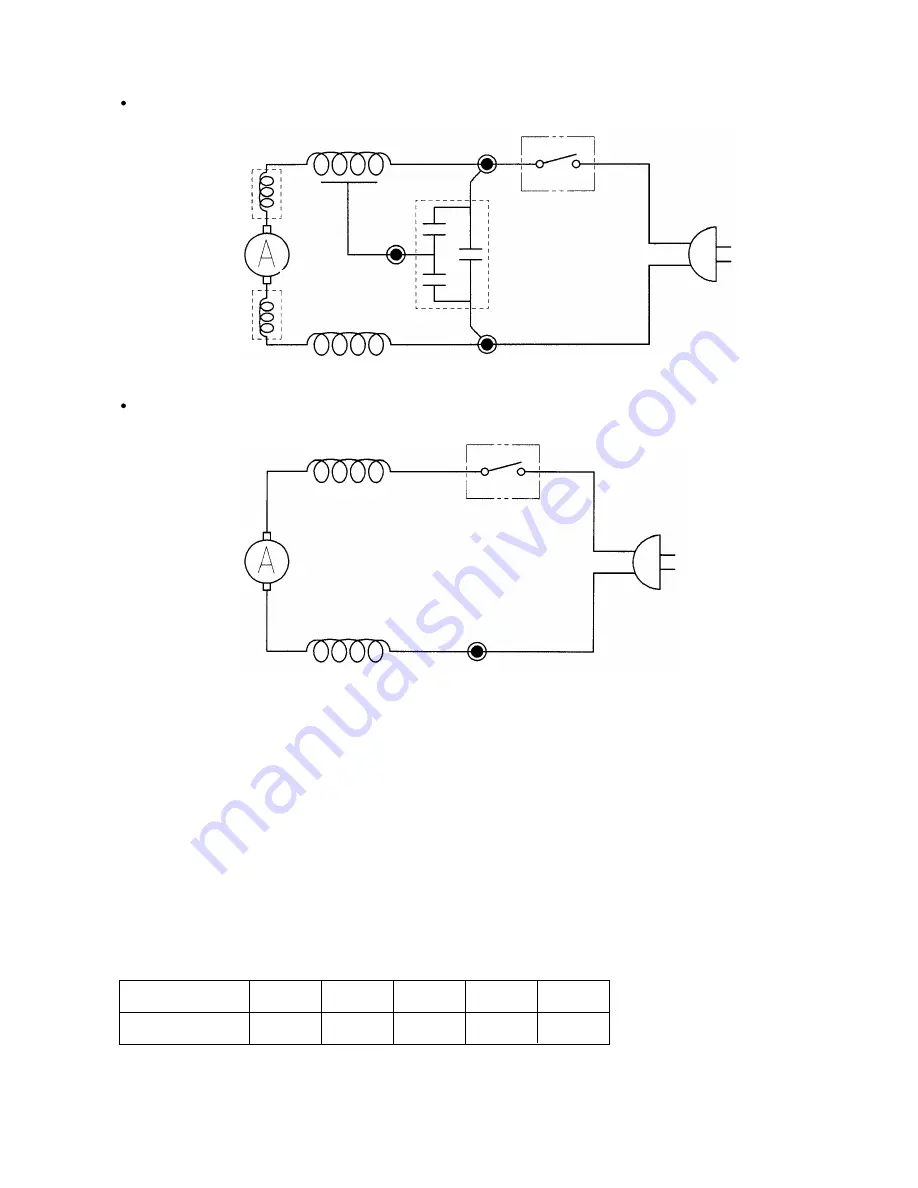
9-1-5. Internal wiring
Wiring diagram for products with noise suppressor
Brown
Connector
Switch
Noise
suppressor
Connector
Armature
Stator
Plug
Blue
Pillar terminal
Stator
Fig. 18
Fig. 19
Wiring diagram for products without noise suppressor
Switch
Connector
Armature
Stator
Stator
Plug
Black
White
9-1-6. Insulation tests
On completion of disassembly and repair, measure the insulation resistance and dielectric strength.
Insulation resistance: 7 M
Ω
or more with DC 500 V Megohm Tester
Dielectric strength:
AC 4,000 V/1 minute, with no abnormalities
• • •
220 V --- 240 V
(and 110 V for U.K. products)
AC 2,500 V/1 minute, with no abnormalities
• • •
110 V --- 127 V
(except U.K. products)
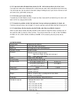
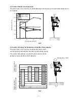
9-1-7. No-load current value
After no-load operation for 30 minutes, the no-load current value should be as follows:
Voltage (V)
Current (A) (Max.)
110
120
220
230
3.8
3.5
2.2
2.1
240
2.0
Summary of Contents for H 45MR
Page 26: ......


