--- 9 ---
8. REFERENCE INFORMATION
8-1. Structure of the Main Body
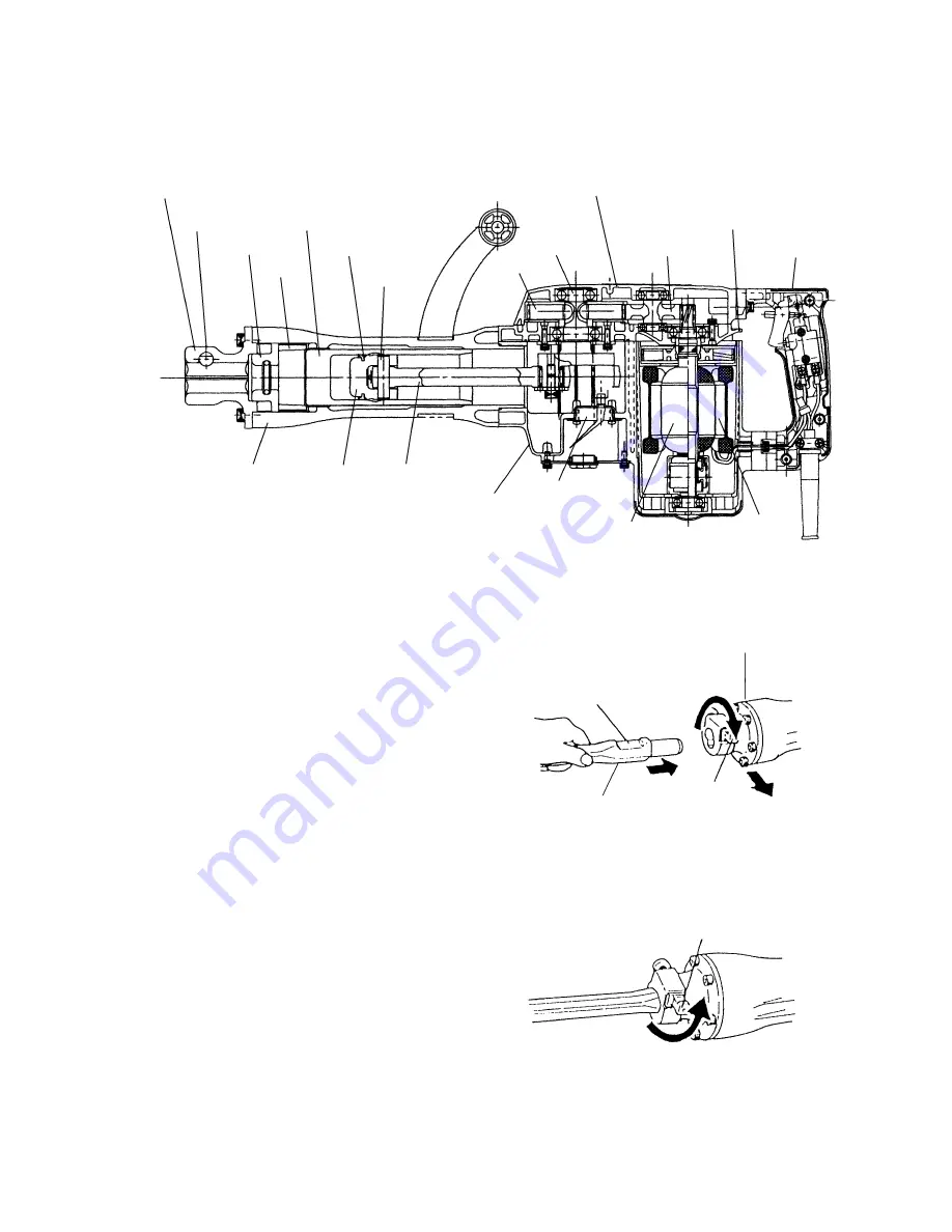
The primary structure of the Model H 65SC is similar with the Model PH-65A, as illustrated. (Fig. 3)
Fig. 3
8-2. Stop Lever [Tool Retainer] (Fig. 4 and Fig. 5)
(1) Clean, then smear the tool shank with
grease or machine oil. (Fig. 4)
(2) Rotate the stop lever 180˚ in a
clockwise direction while pulling it
toward you. Next, insert the tool shank
into the hexagonal hole on the front
cover. (Fig. 4)
(3) Clamp the tool by turning the stop lever
by half a turn in the opposite direction.
(Fig. 5)
Fig. 4
Front Cover
Stop Lever
Shank Sleeve
Mouth
Striker
L Ring
Piston Pin
Final Gear
Crank Shaft
Gear Cover Ass'y
Counter Gear
Inner Cover
Switch Handle
Stator Ass'y
Armature Ass'y
Felt Holder (C)
Ass'y
Housing Ass'y
Connecting Rod
Piston
Cylinder Case
Front Cover
2
1
3
Hold the tool with its flattened
part directed upward.
Tool Shank
Stop Lever
Fig. 5
Stop Lever


