background image

H 65SD3

   DESCRIPTION

    REMARKS

501

339664

CASE (PLASTIC)

1

   DESCRIPTION

    REMARKS

601

985231

COLD CHISEL 520MM (HEX. SHANK TYPE)

1

602

985232

CUTTER W75 X 520MM (HEX. SHANK TYPE)

1

603

985233

SCOOP 546L (HEX. SHANK TYPE)

1

604

996372

BULL POINT 410MM (HEX. SHANK TYPE)

1

605

996373

COLD CHISEL 410MM (HEX. SHANK TYPE)

1

606

996374

CUTTER W75 X 410MM (HEX. SHANK TYPE)

1

607

336375

WHEEL SET

1

608

337337

WHEEL SHAFT SET

1

609

337338

LATCH SET (2 PCS.)

2

610

402616

HAMMER TROLLEY

1

611

980927

GREASE FOR HAMMER.HAMMER DRILL (500G)

1

612

981840

GREASE (A) FOR HAMMER.HAMMER DRILL (30G)

1

613

308471

GREASE FOR HAMMER.HAMMER DRILL (70G)

1

8 - 16

Printed in Japan

- 5 -

                                        (160819N) 

          *ALTERNATIVE PARTS

STANDARD ACCESSORIES   

OPTIONAL ACCESSORIES   

NO. 

USED 

NO. 

USED 

CODE NO. 

CODE NO. 

ITEM 

NO. 

ITEM 

NO. 

Summary of Contents for H 65SD3

Page 1: ...LIST No H 65SD3 F439 Aug 2016 PRODUCT NAME Hitachi Demolition Hammer Model H 65SD3 REPAIR GUIDE 1 1 Precautions on disassembly and reassembly 1 CONTENTS Page Overseas Sales Division H ...

Page 2: ...d remove the fixing bolts use an appropriate heating device to heat the bolts to approximately 80 C 176 F 1 Disassembly of the armature ass y 1 Loosen the four Bolts M4 x 8 81 remove the Cap Cover 82 Cap Rubber 83 Brush Cap 84 and Carbon Brush 85 Be careful not to lose any removed parts 2 Loosen the four Bolts M8 x 40 23 and remove the Cylinder Case 19 Next loosen the Bolt M8 x 16 31 and then remo...

Page 3: ...er 42 2 Disassembly of the crank shaft section 1 Remove the four Bolts M5 x 16 47 which fix the Bearing Cover 46 Then as illustrated in Fig 2 support the lower surface of the Inner Cover 42 with an appropriate tubular jig align an appropriate steel rod with the end surface of the Crank Shaft 48 and press down on the steel rod with a hand press 2 Remove the Ball Bearing 6302VV 39 Distance Ring B 41...

Page 4: ... Housing Ass y 49 2 Take out the Striker 21 Piston 26 and Connecting Rod Ass y 28 in a single body from the Cylinder Case 19 3 Holding the Striker 21 firmly in one hand grasp the Connecting Rod Ass y 28 in the other hand and pull it forcefully to separate it from the Striker 21 4 Extract the Piston Pin 25 from the Piston 26 and separate the Piston Pin 25 from the Connecting Rod Ass y 28 6 Disassem...

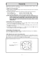
Page 5: ...1401 carefully clean off any grease or other foreign matter from the male and female threads with gasoline thinner or similar cleaning solvents 2 Reassembly of the crank shaft section 1 Press fit the Ball Bearing 6205DD 45 into the Inner Cover 42 and fasten the Bearing Cover 46 onto the Inner Cover 42 with the four Bolts M5 x 16 47 2 Use a proper jig to hold the inner race of the Ball Bearing 6205...

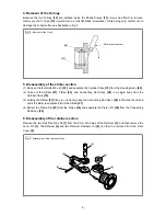
Page 6: ... of the Striker 21 Mount the Striker 21 Either of the above two ways requires a pressing force of more than 30 kg When a hissing sound is heard the Piston 26 is properly inserted in the Striker 21 The hissing is the sound of the compressed air escaping from the Striker 21 when the Piston 26 reaches the respiratory hole in the Striker 21 6 Mounting oil seal A When mounting Oil Seal A 27 on the Pist...

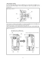
Page 7: ...rmal noise Secure handle A of Handle A B Set 111 to the Handle Weight 60 and Handle Shaft 110 After wiring put the switch lever into the lock ON state and secure handle B NOTE It is impossible to mount handle B without putting the switch lever into the lock ON state 38 61 78 57 56 55 While pulling the Switch Lever 109 all the way push the pushing button to put into lock ON state After securing han...

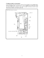
Page 8: ...e Support 104 elastically holds the Switch 97 in place Vinyl Tube A I D 7 x T0 5 x 50 98 covers the internal wire and the Vinyl Tube L55 74 covers the internal wire of the Stator Ass y 72 These tubes are provided to protect the internal wires therefore do not forget to attach them Handle A 104 97 98 72 Internal wire of the Stator Ass y 72 49 74 109 93 94 ...

Page 9: ...etainer 2 3 Insert the Lever Pin 3 into the 20 mm dia hole of the Retainer 2 facing the recessed portion of the Lever Pin 3 to the hexagonal hole of the Front Cover 8 At this time align the 6 mm dia hole of the Retainer 2 with the 7 mm dia hole of the Lever Pin 3 4 Drive the Roll Pin D6 x 55 1 into the 6 mm dia hole side A of the Retainer 2 approximately 6 3 mm under the end surface of the Retaine...

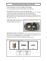
Page 10: ...Rod Ass y 28 Apply specified grease to the sliding portion of the Second Hammer 7 O ring C 9 of the Front Cover 8 hexagonal hole of the Front Cover 8 sliding portion of the Retainer 2 sliding portion of the Front Cover 8 and Lever Pin 3 Fill Nippeco SEP 3A grease in the following parts Fill 78 g of Nippeco SEP 3A grease in the Gear Cover 38 so that the gears are greased Apply Nippeco SEP 3A grease...

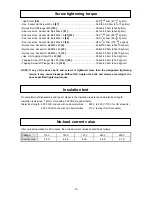
Page 11: ...0 49 N m 20 5 kgf cm Tapping Screw W Flange D4 x 16 100 1 96 0 49 N m 20 5 kgf cm NOTE If any of the above bolts and screws is tightened more than the designated tightening torque it may cause breakage Without fail tighten the bolts and screws according to the above specified tightening torques On completion of disassembly and repair measure the insulation resistance and dielectric strength Insula...

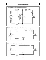
Page 12: ...ot equipped with a noise suppressor Fig 16 Connecting diagram of the 120 V 127 V product Connecting diagram Stator Stator Armature Connector Switch Tube Tube Plug Pillar terminal Connector Noise suppressor Stator Stator Armature Connector Switch Tube Tube Plug Armature Stator Stator Pillar terminal Tube Switch Tube Plug ...

Page 13: ... 92 45 105 1 2 3 6 4 9 11 12 13 14 15 16 17 19 18 21 22 23 24 27 25 26 28 30 31 32 33 38 39 40 41 42 43 46 47 48 49 50 79 80 81 82 83 84 85 86 58 60 62 63 64 47 67 68 50 51 69 70 71 53 72 74 75 76 78 106 77 59 108 105 107 110 96 59 77 90 52 103 95 94 20 7 54 34 65 29 501 111 102 90 90 5 10 37 36 35 93 89 44 57 112 ...

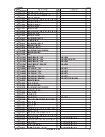
Page 14: ...8 BLACK 4 25 944928 PISTON PIN 1 26 339676 PISTON 1 27 998415 OIL SEAL A 1 28 998434 CONNECTING ROD ASS Y 1 INCLUD 29 29 944921 NEEDLE BEARING NTN 8E NK 18 20 RDO 1 30 956955 CRANK WASHER 1 31 996364 SEAL LOCK HEX SOCKET HD BOLT M8 X 16 1 32 306166 GRIP 1 33 320375 NYLOCK HEX SOCKET HD BOLT M8 X 16 2 34 306165 SIDE HANDLE ASS Y 1 INCLUD 18 32 33 35 324544 FELT PACKING B 1 36 338313 CAP SCREW 1 37 ...

Page 15: ...UIDE 1 72 340928C STATOR ASS Y 110V 1 INCLUD 73 72 340928G STATOR ASS Y 120V 1 INCLUD 73 72 340928D STATOR ASS Y 127V 1 INCLUD 73 72 340928E STATOR ASS Y 220V 230V 1 INCLUD 73 72 340928H STATOR ASS Y 220V 230V 1 INCLUD 73 FOR BRA PAN 73 945932 BRUSH TERMINAL 2 74 322530 VINYL TUBE L55 1 75 944954 BEARING WASHER 1 76 6201DD BALL BEARING 6201DDCMPS2L 1 77 991711 DISTANCE PIECE B 2 78 339692 BACK COV...

Page 16: ...CORD CLIP 1 102 500390Z CORD 1 CORD ARMOR D10 7 102 500453Z CORD 1 CORD ARMOR D10 7 FOR USA CAN MEX 102 500446Z CORD 1 CORD ARMOR D10 7 FOR GBR 230V 102 500467Z CORD 1 CORD ARMOR D10 7 FOR GBR 110V 102 500487Z CORD 1 CORD ARMOR D8 2 FOR BRA 103 958049 CORD ARMOR D8 2 1 103 940778 CORD ARMOR D10 7 1 104 337052 SUPPORT 1 105 339693 NYLOCK BOLT W FLANGE M5 4 106 NAME PLATE 1 107 339691 LEAF SPRING 1 ...

Page 17: ...ISEL 410MM HEX SHANK TYPE 1 606 996374 CUTTER W75 X 410MM HEX SHANK TYPE 1 607 336375 WHEEL SET 1 608 337337 WHEEL SHAFT SET 1 609 337338 LATCH SET 2 PCS 2 610 402616 HAMMER TROLLEY 1 611 980927 GREASE FOR HAMMER HAMMER DRILL 500G 1 612 981840 GREASE A FOR HAMMER HAMMER DRILL 30G 1 613 308471 GREASE FOR HAMMER HAMMER DRILL 70G 1 8 16 Printed in Japan 5 160819N ALTERNATIVE PARTS STANDARD ACCESSORIE...

Reviews: