--- 15 ---
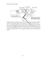
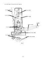
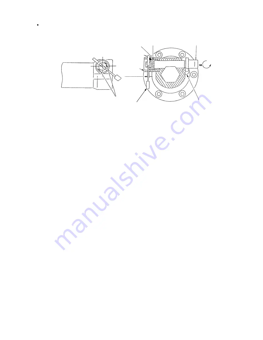
Disassembly procedures are illustrated in Fig. 9. Pull the Stop Lever [2] outward in the direction indicated by
the arrow, and turn it slightly so that its end surface comes to rest on the flange portion of the Front Cover
[7]. Next, turn the Spring Case [4] so that the holes of the spring case are aligned with the Needle Roller [3].
Then, push in Damper (B) [6] with flat-blade screwdrivers to compress the Lever Spring [5]. Finally, while
keeping the Lever Spring [5] compressed, fit a 3 mm or less dia. steel rod into the hole of the Spring Case [4],
and push out the Needle Roller [3]. The Stop Lever [2], Damper (B) [6], and the Lever Spring [5] can then be
taken out.
Lever Spring [5]
Fig. 9
Overlap the end surface of the
Stop Lever [2] on the flange
portion of the Front Cover [7].
Stop Lever [2]
Needle Roller [3]
Damper (B) [6]
Spring
Case [4]
Push Damper (B) [6]
with two flat-blade screwdrivers.
Disassembly of the Stop Lever [2]
3 mm dia. hole
Steel rod
(3 mm or less dia.)


