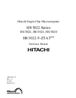
background image

Hitachi Single-Chip Microcomputer

H8/3022 Series

H8/3022, H8/3021, H8/3020

H8/3022 F-ZTAT

TM

Hardware Manual

ADE-602-179
Rev. 1.0
12/6/99
Hitachi,Ltd

Summary of Contents for H8/3020

Page 1: ...Hitachi Single Chip Microcomputer H8 3022 Series H8 3022 H8 3021 H8 3020 H8 3022 F ZTATTM Hardware Manual ADE 602 179 Rev 1 0 12 6 99 Hitachi Ltd ...

Page 2: ...of bodily injury such as aerospace aeronautics nuclear power combustion control transportation traffic safety equipment or medical equipment for life support 4 Design your application so that the product is used within the ranges guaranteed by Hitachi particularly for maximum rating operating supply voltage range heat radiation characteristics installation conditions and other characteristics Hita...

Page 3: ...3 smart card interface Functions have also been added to reduce power consumption in battery powered applications individual modules can be placed in standby and the frequency of the system clock supplied to the chip can be divided down under software control The five MCU operating modes offer a choice of expanded mode single chip mode and address space size enabling the H8 3022 Series to adapt qu...

Page 4: ... General Register Data Formats 23 2 5 2 Memory Data Formats 24 2 6 Instruction Set 26 2 6 1 Instruction Set Overview 26 2 6 2 Instructions and Addressing Modes 27 2 6 3 Tables of Instructions Classified by Function 29 2 6 4 Basic Instruction Formats 39 2 6 5 Notes on Use of Bit Manipulation Instructions 40 2 7 Addressing Modes and Effective Address Calculation 41 2 7 1 Addressing Modes 41 2 7 2 Ef...

Page 5: ...Mode 61 3 6 Memory Map in Each Operating Mode 61 Section 4 Exception Handling 69 4 1 Overview 69 4 1 1 Exception Handling Types and Priority 69 4 1 2 Exception Handling Operation 69 4 1 3 Exception Vector Table 70 4 2 Reset 72 4 2 1 Overview 72 4 2 2 Reset Sequence 72 4 2 3 Interrupts after Reset 74 4 3 Interrupts 74 4 4 Trap Instruction 75 4 5 Stack Status after Exception Handling 75 4 6 Notes on...

Page 6: ...age Notes 102 Section 6 Bus Controller 105 6 1 Overview 105 6 1 1 Features 105 6 1 2 Block Diagram 106 6 1 3 Pin Configuration 107 6 1 4 Register Configuration 107 6 2 Register Descriptions 108 6 2 1 Access State Control Register ASTCR 108 6 2 2 Wait Control Register WCR 109 6 2 3 Wait State Controller Enable Register WCER 110 6 2 4 Address Control Register ADRCR 111 6 3 Operation 113 6 3 1 Area D...

Page 7: ...ister Descriptions 149 7 6 3 Pin Functions in Each Mode 152 7 7 Port 7 155 7 7 1 Overview 155 7 7 2 Register Description 155 7 8 Port 8 156 7 8 1 Overview 156 7 8 2 Register Descriptions 157 7 8 3 Pin Functions 158 7 9 Port 9 159 7 9 1 Overview 159 7 9 2 Register Descriptions 159 7 9 3 Pin Functions 160 7 10 Port A 163 7 10 1 Overview 163 7 10 2 Register Descriptions 164 7 10 3 Pin Functions 166 7...

Page 8: ... 216 8 3 CPU Interface 218 8 3 1 16 Bit Accessible Registers 218 8 3 2 8 Bit Accessible Registers 220 8 4 Operation 221 8 4 1 Overview 221 8 4 2 Basic Functions 222 8 4 3 Synchronization 232 8 4 4 PWM Mode 234 8 4 5 Reset Synchronized PWM Mode 238 8 4 6 Complementary PWM Mode 241 8 4 7 Phase Counting Mode 251 8 4 8 Buffering 253 8 4 9 ITU Output Timing 260 8 5 Interrupts 262 8 5 1 Setting of Statu...

Page 9: ...g Timer 307 10 1 Overview 307 10 1 1 Features 307 10 1 2 Block Diagram 308 10 1 3 Pin Configuration 308 10 1 4 Register Configuration 309 10 2 Register Descriptions 310 10 2 1 Timer Counter TCNT 310 10 2 2 Timer Control Status Register TCSR 311 10 2 3 Reset Control Status Register RSTCSR 313 10 2 4 Notes on Register Access 315 10 3 Operation 317 10 3 1 Watchdog Timer Operation 317 10 3 2 Interval ...

Page 10: ... Interface 383 12 1 Overview 383 12 1 1 Features 383 12 1 2 Block Diagram 384 12 1 3 Pin Configuration 385 12 1 4 Register Configuration 385 12 2 Register Descriptions 386 12 2 1 Smart Card Mode Register SCMR 386 12 2 2 Serial Status Register SSR 388 12 3 Operation 390 12 3 1 Overview 390 12 3 2 Pin Connections 390 12 3 3 Data Format 392 12 3 4 Register Settings 394 12 3 5 Clock 396 12 3 6 Data Tr...

Page 11: ...ng Modes 436 15 2 4 Flash Memory Emulation in RAM 438 15 2 5 Differences between Boot Mode and User Program Mode 439 15 2 6 Block Configuration 440 15 3 Pin Configuration 440 15 4 Register Configuration 441 15 5 Register Descriptions 441 15 5 1 Flash Memory Control Register 1 FLMCR1 441 15 5 2 Flash Memory Control Register 2 FLMCR2 444 15 5 3 Erase Block Register 1 EBR1 445 15 5 4 Erase Block Regi...

Page 12: ...1 Block Diagram 486 16 2 Oscillator Circuit 487 16 2 1 Connecting a Crystal Resonator 487 16 2 2 External Clock Input 489 16 3 Duty Adjustment Circuit 492 16 4 Prescalers 492 16 5 Frequency Divider 492 16 5 1 Register Configuration 492 16 5 2 Division Control Register DIVCR 493 16 5 3 Usage Notes 493 Section 17 Power Down State 495 17 1 Overview 495 17 2 Register Configuration 497 17 2 1 System Co...

Page 13: ...ics 519 18 2 Electrical characteristics of Flash Memory Version 520 18 2 1 Absolute Maximum Ratings 520 18 2 2 DC Characteristics 521 18 2 3 AC Characteristics 525 18 2 4 A D Conversion Characteristics 530 18 2 5 Flash Memory Characteristics 531 18 3 Operational Timing 532 18 3 1 Bus Timing 532 18 3 2 Control Signal Timing 536 18 3 3 Clock Timing 538 18 3 4 TPC and I O Port Timing 538 18 3 5 ITU T...

Page 14: ...C 10 Port B Block Diagrams 651 Appendix D Pin States 654 D 1 Port States in Each Mode 654 D 2 Pin States at Reset 656 Appendix E Timing of Transition to and Recovery from Hardware Standby Mode 659 Appendix F Product Code Lineup 660 Appendix G Package Dimensions 661 Appendix H Comparison of H8 300H Series Product Specifications 663 H 1 Differences between H8 3039F and H8 3022F 663 ...

Page 15: ...hdog timer WDT a serial communication interface SCI an A D converter I O ports and other facilities The H8 3022 Series consists of four models the H8 3022 with 256 kbytes of ROM and 8 kbytes of RAM the H8 3021 with 192 kbytes of ROM and 8 kbytes of RAM and the H8 3020 with 128 kbytes of ROM and 4 kbytes of RAM The five MCU operating modes offer a choice of expanded mode single chip mode and addres...

Page 16: ...ned and unsigned multiply instructions 8 bits 8 bits 16 bits 16 bits Signed and unsigned divide instructions 16 bits 8 bits 32 bits 16 bits Bit accumulator function Bit manipulation instructions with register indirect specification of bit positions Memory H8 3022 ROM 256 kbytes RAM 8 kbytes H8 3021 ROM 192 kbytes RAM 8 kbytes H8 3020 ROM 128 kbytes RAM 4 kbytes Interrupt Five external interrupt pi...

Page 17: ...up Non overlap mode available Watchdog timer Reset signal can be generated by overflow WDT 1 channel Reset signal can be output externally However not available with the F ZTAT version Usable as an interval timer Serial Selection of asynchronous or synchronous mode communication Full duplex can transmit and receive simultaneously interface SCI On chip baud rate generator 2 channels Smart card inte...

Page 18: ...ip clock oscillator Product lineup Model 3V Package ROM HD64F3022F 80 pin QFP FP 80A Flash memory HD64F3022TE 80 pin TQFP TFP 80C HD6433022F 80 pin QFP FP 80A Mask ROM HD6433022TE 80 pin TQFP TFP 80C HD6433021F 80 pin QFP FP 80A Mask ROM HD6433021TE 80 pin TQFP TFP 80C HD6433020F 80 pin QFP FP 80A Mask ROM HD6433020TE 80 pin TQFP TFP 80C Note Normal mode cannot be used with this LSI ...

Page 19: ... A6 P15 A5 P14 A4 P13 A3 P12 A2 P11 A1 P10 A0 P95 SCK1 IRQ5 P94 SCK0 IRQ4 P93 RxD1 P92 RxD0 P91 TxD1 P90 TxD0 P53 A19 P52 A18 P51 A17 P50 A16 Data bus lower Bus controller Clock osc H8 300H CPU ROM Flash memory masked ROM RAM 16 bit integrated timer unit ITU Programmable timing pattern controller TPC Interrupt controller Serial communication interface SCI 2 channel Watchdog timer WDT A D converter...

Page 20: ...1 PA0 TP0 TCLKA PA1 TP1 TCLKB PA2 TP2 TIOCA0 TCLKC PA3 TP3 TIOCB0 TCLKD PA4 TP4 TIOCA1 A23 PA5 TP5 TIOCB1 A22 PA6 TP6 TIOCA2A21 PA7 TP7 TIOCB2 A20 40 39 38 37 36 35 34 33 32 31 30 29 28 27 26 25 24 23 22 21 A17 P51 A16 P50 A15 P27 A14 P26 A13 P25 A12 P24 A11 P23 A10 P22 A9 P21 A8 P20 VSS A7 P17 A6 P16 A5 P15 A4 P14 A3 P13 A2 P12 A1 P11 A0 P10 VCC TIOCA 3 TP 8 PB 0 TIOCB 3 TP 9 PB 1 TIOCA 4 TP 10 P...

Page 21: ...TIOCB4 PB3 TP11 TIOCB4 PB3 TP11 TIOCB4 PB3 TP11 TIOCB4 PB3 TP11 TIOCB4 5 PB4 TP12 TOCXA4 PB4 TP12 TOCXA4 PB4 TP12 TOCXA4 PB4 TP12 TOCXA4 PB4 TP12 TOCXA4 6 PB5 TP13 TOCXB4 PB5 TP13 TOCXB4 PB5 TP13 TOCXB4 PB5 TP13 TOCXB4 PB5 TP13 TOCXB4 7 MD2 MD2 MD2 MD2 MD2 8 PB7 TP15 ADTRG PB7 TP15 ADTRG PB7 TP15 ADTRG PB7 TP15 ADTRG PB7 TP15 ADTRG 9 P90 TxD0 P90 TxD0 P90 TxD0 P90 TxD0 P90 TxD0 10 P92 RxD0 P92 RxD...

Page 22: ...P20 32 A9 A9 P21 A9 P21 A9 P21 33 A10 A10 P22 A10 P22 A10 P22 34 A11 A11 P23 A11 P23 A11 P23 35 A12 A12 P24 A12 P24 A12 P24 36 A13 A13 P25 A13 P25 A13 P25 37 A14 A14 P26 A14 P26 A14 P26 38 A15 A15 P27 A15 P27 A15 P27 39 A16 A16 P50 A16 P50 A16 P50 40 A17 A17 P51 A17 P51 A17 P51 41 A18 A18 P52 A18 P52 A18 P52 42 A19 A19 P53 A19 P53 A19 P53 43 P60 WAIT P60 WAIT P60 WAIT P60 WAIT P60 44 MD0 MD0 MD0 M...

Page 23: ...4 AN4 64 P75 AN5 P75 AN5 P75 AN5 P75 AN5 P75 AN5 65 P76 AN6 P76 AN6 P76 AN6 P76 AN6 P76 AN6 66 P77 AN7 P77 AN7 P77 AN7 P77 AN7 P77 AN7 67 AVCC AVCC AVCC AVCC AVCC 68 P80 IRQ0 P80 IRQ0 P80 IRQ0 P80 IRQ0 P80 IRQ0 69 P81 IRQ1 P81 IRQ1 P81 IRQ1 P81 IRQ1 P81 IRQ1 70 P91 TxD1 P91 TxD1 P91 TxD1 P91 TxD1 P91 TxD1 71 P93 RxD1 P93 RxD1 P93 RxD1 P93 RxD1 P93 RxD1 72 P95 SCK1 IRQ5 P95 SCK1 IRQ5 P95 SCK1 IRQ5 ...

Page 24: ...A1 PA4 TP4 TIOCA1 A23 PA4 TP4 TIOCA1 PA4 TP4 TIOCA1 A23 PA4 TP4 TIOCA1 78 PA5 TP5 TIOCB1 PA5 TP5 TIOCB1 A22 PA5 TP5 TIOCB1 PA5 TP5 TIOCB1 A22 PA5 TP5 TIOCB1 79 PA6 TP6 TIOCA2 PA6 TP6 TIOCA2 A21 PA6 TP6 TIOCA2 PA6 TP6 TIOCA2 A21 PA6 TP6 TIOCA2 80 PA7 TP7 TIOCB2 A20 PA7 TP7 TIOCB2 A20 PA7 TP7 TIOCB2 Notes Pins marked NC should be left unconnected Masked ROM RESO Flash Memory FWE ...

Page 25: ...les of crystal resonator and external clock input see section 16 Clock Pulse Generator EXTAL 51 Input For connection to a crystal resonator or input of an external clock signal For examples of crystal resonator and external clock input see section 16 Clock Pulse Generator ø 46 Output System clock Supplies the system clock to external devices Operating mode control MD2 MD1 MD0 7 45 44 Input Mode 2 ...

Page 26: ... output Data bus Bidirectional data bus Bus control AS 54 Output Address strobe Goes low to indicate valid address output on the address bus RD 55 Output Read Goes low to indicate reading from the external address space WR 56 Output Write Goes low to indicate writing to the external address space indicates valid data on the data bus WAIT 43 Input Wait Requests insertion of wait states in bus cycle...

Page 27: ...system power supply 0 V I O ports P17 to P10 29 to 22 Input output Port 1 Eight input output pins The direction of each pin can be selected in the port 1 data direction register P1DDR P27 to P20 38 to 31 Input output Port 2 Eight input output pins The direction of each pin can be selected in the port 2 data direction register P2DDR P37 to P30 20 to 13 Input output Port 3 Eight input output pins Th...

Page 28: ... selected in the port 9 data direction register P9DDR PA7 to PA0 80 to 73 Input output Port A Eight input output pins The direction of each pin can be selected in the port A data direction register PADDR PB7 PB5 to PB0 8 6 to 1 Input output Port B Seven input output pins The direction of each pin can be selected in the port B data direction register PBDDR ...

Page 29: ...ithout alteration General register architecture Sixteen 16 bit general registers also usable as sixteen 8 bit registers or eight 32 bit registers Sixty two basic instructions 8 16 32 bit arithmetic and logic instructions Multiply and divide instructions Powerful bit manipulation instructions Eight addressing modes Register direct Rn Register indirect ERn Register indirect with displacement d 16 ER...

Page 30: ...to power down state by SLEEP instruction 2 1 2 Differences from H8 300 CPU In comparison to the H8 300 CPU the H8 300H has the following enhancements More general registers Eight 16 bit registers have been added Expanded address space Advanced mode supports a maximum 16 Mbyte address space Normal mode supports the same 64 kbyte address space as the H8 300 CPU Enhanced addressing The addressing mod...

Page 31: ... mode supports up to 16 Mbytes See figure 2 1 Unless specified otherwise all descriptions in this manual refer to advanced mode CPU operating modes Normal mode Advanced mode Maximum 64 kbytes program and data areas combined Maximum 16 Mbytes program and data areas combined Note Normal mode cannot be used with this LSI Figure 2 1 CPU Operating Modes ...

Page 32: ...ode Figure 2 2 shows the address ranges of the H8 3022 Series For further details see section 3 6 Memory Map in Each Operating Mode The 1 Mbyte operating mode uses 20 bit addressing The upper 4 bits of effective addresses are ignored H 000000 H FFFFFF b 16 Mbyte mode a 1 Mbyte mode 2 Advanced mode 1 Normal mode 64 Kbyte mode Note Normal mode cannot be used with this LSI H 00000 H FFFFF H 00000 H F...

Page 33: ...2 E3 E4 E5 E6 E7 R0H R1H R2H R3H R4H R5H R6H R7H R0L R1L R2L R3L R4L R5L R6L R7L 0 7 0 7 0 15 SP 23 0 PC 7 CCR 6 5 4 3 2 1 0 I UI H U N Z V C General Registers ERn Control Registers CR Legend SP PC CCR I UI H U N Z V C Stack pointer Program counter Condition code register Interrupt mask bit User bit or interrupt mask bit Half carry flag User bit Negative flag Zero flag Overflow flag Carry flag Fig...

Page 34: ...0 to E7 and R R0 to R7 These registers are functionally equivalent providing a maximum sixteen 16 bit registers The E registers E0 to E7 are also referred to as extended registers The R registers divide into 8 bit general registers designated by the letters RH R0H to R7H and RL R0L to R7L These registers are functionally equivalent providing a maximum sixteen 8 bit registers Figure 2 4 illustrates...

Page 35: ...tiple of 2 bytes so the least significant PC bit is ignored When an instruction is fetched the least significant PC bit is regarded as 0 Condition Code Register CCR This 8 bit register contains internal CPU status information including the interrupt mask bit I and half carry H negative N zero Z overflow V and carry C flags Bit 7 Interrupt Mask Bit I Masks interrupts other than NMI when set to 1 NM...

Page 36: ...er times Bit 0 Carry Flag C Set to 1 when a carry occurs and cleared to 0 otherwise Used by Add instructions to indicate a carry Subtract instructions to indicate a borrow Shift and rotate instructions to store the value shifted out of the end bit The carry flag is also used as a bit accumulator by bit manipulation instructions Some instructions leave flag bits unchanged Operations can be performe...

Page 37: ...neral Register Data Formats Figures 2 6 and 2 7 show the data formats in general registers 7 RnH RnL RnH RnL RnH RnL 1 bit data 1 bit data 4 bit BCD data 4 bit BCD data Byte data Byte data 6 5 4 3 2 1 0 7 0 Don t care 7 6 5 4 3 2 1 0 7 0 Don t care Don t care 7 0 4 3 Lower digit Upper digit 7 4 3 Lower digit Upper digit Don t care 0 7 0 Don t care MSB LSB Don t care 7 0 MSB LSB Data Type Data Form...

Page 38: ... General Register Data Formats 2 5 2 Memory Data Formats Figure 2 8 shows the data formats on memory The H8 300H CPU can access word data and longword data on memory but word or longword data must begin at an even address If an attempt is made to access word or longword data at an odd address no address error occurs but the least significant bit of the address is regarded as 0 so the access starts...

Page 39: ...data Word data Longword data Address Data Type Data Format Address 2m Address 2m 1 Address 2n Address 2n 1 Address 2n 2 Address 2n 3 Figure 2 8 Memory Data Formats When ER7 SP is used as an address register to access the stack the operand size should be word size or longword size ...

Page 40: ... operations AND OR XOR NOT 4 Shift operations SHAL SHAR SHLL SHLR ROTL ROTR ROTXL ROTXR 8 Bit manipulation BSET BCLR BNOT BTST BAND BIAND BOR BIOR BXOR BIXOR BLD BILD BST BIST 14 Branch Bcc 3 JMP BSR JSR RTS 5 System control TRAPA RTE SLEEP LDC STC ANDC ORC XORC NOP 9 Block data transfer EEPMOV 1 Total 62 types Notes 1 POP W Rn is identical to MOV W SP Rn PUSH W Rn is identical to MOV W Rn SP POP ...

Page 41: ...ERn d 24 ERn ERn ERn aa 8 aa 16 aa 24 d 8 PC d 16 PC aa 8 Implied Data MOV BWL BWL BWL BWL BWL BWL B BWL BWL transfer POP PUSH WL MOVFPE MOVTPE B Arithmetic ADD CMP BWL BWL operations SUB WL BWL ADDX SUBX B B ADDS SUBS L INC DEC BWL DAA DAS B MULXU MULXS DIVXU DIVXS BW NEG BWL EXTU EXTS WL Logic operations AND OR XOR BWL BWL NOT BWL Shift instructions BWL Bit manipulation B B B Branch Bcc BSR JMP ...

Page 42: ...truction xx Rn ERn d 16 ERn d 24 ERn ERn ERn aa 8 aa 16 aa 24 d 8 PC d 16 PC aa 8 Implied System TRAPA control RTE SLEEP LDC B B W W W W W W STC B W W W W W W ANDC ORC XORC B NOP Block data transfer BW Legend B Byte W Word L Longword ...

Page 43: ...ister EAd Destination operand EAs Source operand CCR Condition code register N N negative flag of CCR Z Z zero flag of CCR V V overflow flag of CCR C C carry flag of CCR PC Program counter SP Stack pointer IMM Immediate data disp Displacement Addition Subtraction Multiplication Division Logical AND Logical OR Exclusive logical OR Move NOT logical complement 3 8 16 24 3 8 16 or 24 bit length Note G...

Page 44: ... Cannot be used in the H8 3022 Series MOVTPE B Rs EAs Cannot be used in the H8 3022 Series POP W L SP Rn Pops a general register from the stack POP W Rn is identical to MOV W SP Rn Similarly POP L ERn is identical to MOV L SP ERn PUSH W L Rn SP Pushes a general register onto the stack PUSH W Rn is identical to MOV W Rn SP Similarly PUSH L ERn is identical to MOV L ERn SP Note Size refers to the op...

Page 45: ...gister INC DEC B W L Rd 1 Rd Rd 2 Rd Increments or decrements a general register by 1 or 2 Byte operands can be incremented or decremented by 1 only ADDS SUBS L Rd 1 Rd Rd 2 Rd Rd 4 Rd Adds or subtracts the value 1 2 or 4 to or from data in a 32 bit register DAA DAS B Rd decimal adjust Rd Decimal adjusts an addition or subtraction result in a general register by referring to CCR to produce 4 bit B...

Page 46: ...r with data in another general register or with immediate data and sets CCR according to the result NEG B W L 0 Rd Rd Takes the two s complement arithmetic complement of data in a general register EXTS W L Rd sign extension Rd Extends byte data in the lower 8 bits of a 16 bit register to word data or extends word data in the lower 16 bits of a 32 bit register to longword data by extending the sign...

Page 47: ...ter and another general register or immediate data NOT B W L Rd Rd Takes the one s complement of general register contents Note Size refers to the operand size B Byte W Word L Longword Table 2 6 Shift Instructions Instruction Size Function SHAL SHAR B W L Rd shift Rd Performs an arithmetic shift on general register contents SHLL SHLR B W L Rd shift Rd Performs a logical shift on general register c...

Page 48: ...eral register or memory operand The bit number is specified by 3 bit immediate data or the lower 3 bits of a general register BTST B bit No of EAd Z Tests a specified bit in a general register or memory operand and sets or clears the Z flag accordingly The bit number is specified by 3 bit immediate data or the lower 3 bits of a general register BAND B C bit No of EAd C ANDs the carry flag with a s...

Page 49: ...y flag with the inverse of a specified bit in a general register or memory operand and stores the result in the carry flag The bit number is specified by 3 bit immediate data BLD B bit No of EAd C Transfers a specified bit in a general register or memory operand to the carry flag BILD B bit No of EAd C Transfers the inverse of a specified bit in a general register or memory operand to the carry fl...

Page 50: ...BLS Low or same C Z 1 Bcc BHS Carry clear high or same C 0 BCS BLO Carry set low C 1 BNE Not equal Z 0 BEQ Equal Z 1 BVC Overflow clear V 0 BVS Overflow set V 1 BPL Plus N 0 BMI Minus N 1 BGE Greater or equal N V 0 BLT Less than N V 1 BGT Greater than Z N V 0 BLE Less or equal Z N V 1 JMP Branches unconditionally to a specified address BSR Branches to a subroutine at a specified address JSR Branch...

Page 51: ...m memory data is read by word access STC B W CCR EAd Transfers the CCR contents to a destination location The condition code register size is one byte but in transfer to memory data is written by word access ANDC B CCR IMM CCR Logically ANDs the condition code register with immediate data ORC B CCR IMM CCR Logically ORs the condition code register with immediate data XORC B CCR IMM CCR Logically e...

Page 52: ...next EEPMOV W if R4 0 then repeat ER5 ER6 R4 1 R4 until R4 0 else next Transfers a data block according to parameters set in general registers R4L or R4 ER5 and ER6 R4L or R4 Size of block bytes ER5 Starting source address ER6 Starting destination address Execution of the next instruction begins as soon as the transfer is completed ...

Page 53: ...d by 3 bits data registers by 3 bits or 4 bits Some instructions have two register fields Some have no register field Effective Address Extension Eight 16 or 32 bits specifying immediate data an absolute address or a displacement A 24 bit address or displacement is treated as 32 bit data in which the first 8 bits are 0 H 00 Condition Field Specifies the branching condition of Bcc instructions Figu...

Page 54: ...t pins The intended purpose of this BCLR instruction is to switch PA0 from output to input Before Execution of BCLR Instruction PA7 PA6 PA5 PA4 PA3 PA2 PA1 PA0 Input output Input Input Output Output Output Output Output Output DDR 0 0 1 1 1 1 1 1 Execution of BCLR Instruction BCLR 0 PADDR Clear bit 0 in data direction register After Execution of BCLR Instruction PA7 PA6 PA5 PA4 PA3 PA2 PA1 PA0 Inp...

Page 55: ... or absolute aa 8 addressing mode to specify an operand and register direct BSET BCLR BNOT and BTST instructions or immediate 3 bit addressing mode to specify a bit number in the operand Table 2 11 Addressing Modes No Addressing Mode Symbol 1 Register direct Rn 2 Register indirect ERn 3 Register indirect with displacement d 16 ERn d 24 ERn 4 Register indirect with post increment Register indirect ...

Page 56: ...sult become the address of a memory operand The result is also stored in the address register The value subtracted is 1 for byte access 2 for word access or 4 for longword access For word or longword access the resulting register value should be even 5 Absolute Address aa 8 aa 16 or aa 24 The instruction code contains the absolute address of a memory operand The absolute address may be 8 bits long...

Page 57: ...s an 8 bit absolute address specifying a memory operand This memory operand contains a branch address The memory operand is accessed by longword access The first byte of the memory operand is ignored generating a 24 bit branch address See figure 2 10 The upper bits of the 8 bit absolute address are assumed to be 0 H 0000 so the address range is 0 to 255 H 000000 to H 0000FF Note that the first par...

Page 58: ... contents 31 0 23 0 Register indirect with displacement d 16 ERn d 24 ERn 3 op r General register contents 31 0 23 0 disp Sign extension disp Register indirect with post increment or pre decrement 4 General register contents 31 0 23 0 1 2 or 4 op r General register contents 31 0 23 0 1 2 or 4 op r 1 for a byte operand 2 for a word operand 4 for a longword operand Register indirect with post increm...

Page 59: ...ective Address Absolute address aa 8 5 op Program counter relative d 8 PC or d 16 PC 7 0 23 0 abs 23 0 8 7 aa 16 op abs 23 0 16 15 H FFFF Sign extension aa 24 op 23 0 abs Immediate xx 8 xx 16 or xx 32 6 Operand is immediate data op disp 23 0 PC contents disp op IMM Sign extension ...

Page 60: ...ect aa 8 8 op 23 0 abs 23 0 8 7 H 0000 Memory contents 31 0 abs Legend r rm rn op disp IMM abs Note Normal mode cannot be used with this LSI Register field Operation field Displacement Immediate data Absolute address Advanced mode op 23 0 abs 23 0 8 7 H 0000 15 0 abs 16 15 Normal mode H 00 Memory contents ...

Page 61: ...cates the state transitions Processing states Program execution state Reset state Power down state The CPU executes program instructions in sequence A transient state in which the CPU executes a hardware sequence saving PC and CCR fetching a vector etc in response to a reset interrupt or other exception The CPU and all on chip supporting modules are initialized and halted The CPU is halted to cons...

Page 62: ...tions are accepted at all times in the program execution state Table 2 14 Exception Handling Types and Priority Priority Type of Exception Detection Timing Start of Exception Handling High Reset Synchronized with clock Exception handling starts immediately when RES changes from low to high Interrupt End of instruction execution or end of exception handling When an interrupt is requested exception ...

Page 63: ...ware standby mode Hardware standby mode Power down state End of exception handling Exception Interrupt SLEEP instruction with SSBY 0 SLEEP instruction with SSBY 1 NMI IRQ IRQ or IRQ interrupt STBY high RES low RES high 0 1 2 1 2 Notes 1 2 From any state except hardware standby mode a transition to the reset state occurs whenever goes low From any state a transition to hardware standby mode occurs ...

Page 64: ... the stack Next if the UE bit in the system control register SYSCR is set to 1 the CPU sets this set to 1 the CPU sets the I bit in the condition code register to 1 If the UE bit is cleared to 0 the CPU sets both the I bit and the UI bit in the condition code register to 1 Then the CPU fetches a start address from the exception vector table and execution branches to that address Figure 2 14 shows ...

Page 65: ...the system control register SYSCR CPU operations stop immediately after execution of the SLEEP instruction but the contents of CPU registers are retained Software Standby Mode A transition to software standby mode is made if the SLEEP instruction is executed while the SSBY bit is set to 1 in SYSCR The CPU and clock halt and all on chip supporting modules stop operating The on chip supporting modul...

Page 66: ...ternal address space Access to the external address space can be controlled by the bus controller 2 9 2 On Chip Memory Access Timing On chip memory is accessed in two states The data bus is 16 bits wide permitting both byte and word access Figure 2 15 shows the on chip memory access cycle Figure 2 16 indicates the pin states T state Bus cycle Internal address bus Internal read signal Internal data...

Page 67: ...s The data bus is 8 or 16 bits wide depending on the register being accessed Figure 2 17 shows the on chip supporting module access timing Figure 2 18 indicates the pin states Internal address bus Internal read signal Internal data bus Internal write signal Address Internal data bus ø T state Bus cycle 1 T state 2 T state 3 Read access Write access Write data Read data Figure 2 17 Access Cycle for...

Page 68: ...Pin States during Access to On Chip Supporting Modules 2 9 4 Access to External Address Space The external address space is divided into eight areas areas 0 to 7 Bus controller settings determine whether each area accessed in two or three states For details see section 6 Bus Controller ...

Page 69: ...1 1 Single chip advanced mode Enabled Enabled 2 Notes 1 If the RAM enable bit RAME in the system control register SYSCR is cleared to 0 these addresses become external addresses 2 In mode 7 clearing bit RAME in SYSCR to 0 and reading the on chip RAM always return H FF and write access is ignored For details see section 14 3 Operation For the address space size there are two choices 1 Mbyte or 16 M...

Page 70: ...ven modes The inputs at the mode pins must not be changed during operation 3 1 2 Register Configuration The H8 3022 Series has a mode control register MDCR that indicates the inputs at the mode pins MD2 and MD0 and a system control register SYSCR Table 3 2 summarizes these registers Table 3 2 Registers Address Name Abbreviation R W Initial Value H FFF1 Mode control register MDCR R Undetermined H F...

Page 71: ... mode Reserved bits Note Determined by pins MD to MD 2 0 Bits 7 and 6 Reserved These bits cannot be modified and are always read as 1 Bits 5 to 3 Reserved These bits cannot be modified and are always read as 0 Bits 2 to 0 Mode Select 2 to 0 MDS2 to MDS0 These bits indicate the logic levels at pins MD2 to MD0 the current operating mode MDS2 to MDS0 correspond to MD2 to MD0 MDS1 and MDS0 are read on...

Page 72: ...ts the valid edge of the NMI input Reserved bit RAM enable Enables or disables on chip RAM Standby timer select 2 to 0 These bits select the waiting time at recovery from software standby mode Bit 7 Software Standby SSBY Enables transition to software standby mode For further information about software standby mode see section 17 Power Down State When software standby mode is exited by an external...

Page 73: ...iting time 131 072 states 1 0 1 Waiting time 1 024 states 1 1 Illegal setting Bit 3 User Bit Enable UE Selects whether to use the UI bit in the condition code register as a user bit or an interrupt mask bit Bit 3 UE Description 0 UI bit in CCR is used as an interrupt mask bit 1 UI bit in CCR is used as a user bit Initial value Bit 2 NMI Edge Select NMIEG Selects the valid edge of the NMI input Bit...

Page 74: ...s P1DDR P2DDR and P5DDR must be set to 1 The address bus width can be selected freely by setting DDR of ports 1 2 and 5 The initial bus mode after a reset is 8 bits with 8 bit access to all areas 3 4 4 Mode 6 Ports 1 2 and 5 and port A PA7 to PA4 function as address pins A23 to A0 permitting access to a maximum 16 Mbyte address space but following a reset these pins except for A20 are input ports ...

Page 75: ...not be used in these modes 2 Initial state These pins become address output pins when the corresponding bits in the data direction registers P1DDR P2DDR P5DDR are set to 1 3 Initial state A20 is always an address output pin PA6 to PA4 are switched over to A23 to A21 output by writing 0 in bits 7 to 5 of ADRCR 3 6 Memory Map in Each Operating Mode Figure 3 1 shows a memory map of the H8 3022 Figure...

Page 76: ...FFF10 H FFF1B H FFF1C H FFFFF Note External addresses can be accessed by disabling on chip RAM Mode 3 16 Mbyte expanded modes with on chip ROM disabled H 000000 H 0000FF H 007FFF 8 bit memory indirect addresses 16 bit absolute addresses first half H 1FFFFF H 200000 Area 0 Area 1 Area 2 Area 3 Area 4 Area 5 Area 6 Area 7 External address space Vector area On chip RAM External address space Internal...

Page 77: ... indirect addresses 16 bit absolute addresses first half H 03FFFF H 040000 H 1FFFFF H 200000 H 3FFFFF H 400000 H 5FFFFF H 600000 H 7FFFFF H 800000 H 9FFFFF H A00000 H BFFFFF H C00000 H DFFFFF H E00000 Area 0 Area 1 Area 2 Area 3 Area 4 Area 5 Area 6 Area 7 External address space Vector area On chip ROM On chip RAM External address space Internal I O registers 8 bit absolute addresses 16 bit absolu...

Page 78: ...FF10 H FFF1B H FFF1C H FFFFF Mode 3 16 Mbyte expanded modes with on chip ROM disabled H 000000 H 0000FF H 007FFF 8 bit memory indirect addresses 16 bit absolute addresses first half H 1FFFFF H 200000 Area 0 Area 1 Area 2 Area 3 Area 4 Area 5 Area 6 Area 7 External address space Vector area On chip RAM External address space Internal I O registers 8 bit absolute addresses 16 bit absolute addresses ...

Page 79: ...ses first half Vector area On chip ROM On chip RAM Internal I O registers 8 bit absolute addresses 16 bit absolute addresses second half H FDF10 H FFF00 H FFF0F H FFF1C H FFFFF H 2FFFF H 07FFF H F8000 Notes Reserved 1 H 000000 H 0000FF H 007FFF 8 bit memory indirect addresses 16 bit absolute addresses first half H 02FFFF H 030000 H 03FFFF H 040000 H 1FFFFF H 200000 H 3FFFFF H 400000 H 5FFFFF H 600...

Page 80: ...C H FFFFF Mode 3 16 Mbyte expanded modes with on chip ROM disabled H 000000 H 0000FF H 007FFF 8 bit memory indirect addresses 16 bit absolute addresses first half H 1FFFFF H 200000 Area 0 Area 1 Area 2 Area 3 Area 4 Area 5 Area 6 Area 7 External address space Vector area On chip RAM 2 Reserved 1 External address space Internal I O registers 8 bit absolute addresses 16 bit absolute addresses second...

Page 81: ... half Vector area On chip ROM On chip RAM Internal I O registers 8 bit absolute addresses 16 bit absolute addresses second half H FEF10 H FFF00 H FFF0F H FFF1C H FFFFF H 07FFF H 1FFFF H F8000 Notes Reserved 1 H 000000 H 0000FF H 007FFF 8 bit memory indirect addresses 16 bit absolute addresses first half H 01FFFF H 020000 H 03FFFF H 040000 H 1FFFFF H 200000 H 3FFFFF H 400000 H 5FFFFF H 600000 H 7FF...

Page 82: ...ts immediately after a low to high transition at the RES pin Interrupt Interrupt requests are handled when execution of the current instruction or handling of the current exception is completed Low Trap instruction TRAPA Started by execution of a trap instruction TRAPA 4 1 2 Exception Handling Operation Exceptions originate from various sources Trap instructions and interrupts are handled as follo...

Page 83: ...ors are assigned to different exception sources Table 4 2 lists the exception sources and their vector addresses Exception sources Reset Interrupts Trap instruction External interrupts Internal interrupts NMI IRQ IRQ IRQ IRQ 25 interrupts from on chip supporting modules 0 1 4 5 Figure 4 1 Exception Sources ...

Page 84: ...2 to H 0013 H 0024 to H 0027 10 H 0014 to H 0015 H 0028 to H 002B 11 H 0016 to H 0017 H 002C to H 002F External interrupt IRQ0 12 H 0018 to H 0019 H 0030 to H 0033 IRQ1 13 H 001A to H 001B H 0034 to H 0037 Reserved for system use 14 H 001C to H 001D H 0038 to H 003B 15 H 001E to H 001F H 003C to H 003F External interupt IRQ4 16 H 0020 to H 0021 H 0040 to H 0043 IRQ5 17 H 0022 to H 0023 H 0044 to H...

Page 85: ...RES pin low for at least 20 ms at power up To reset the chip during operation hold the RES pin low for at least 10 system clock ø cycles When using the flash memory version hold at Low level for a least 1usec See appendix D 2 Pin States at Reset for the states of the pins in the reset state When the RES pin goes high after being held low for the necessary time the H8 3022 Series chip starts reset ...

Page 86: ...al Internal data bus 16 bit width Vector fetch Internal processing Prefetch of first program instruction 1 3 2 4 5 6 Address of reset vector 1 H 000000 3 H 000002 Start address contents of reset vector Start address First instruction of program Figure 4 2 Reset Sequence Modes 5 and 7 ...

Page 87: ...request interrupts are the watchdog timer WDT 16 bit integrated timer unit ITU serial communication interface SCI and A D converter Each interrupt source has a separate vector address NMI is the highest priority interrupt and is always accepted Interrupts are controlled by the interrupt controller The interrupt controller can assign interrupts other than NMI to two priority levels and arbitrate be...

Page 88: ... the stack after completion of trap instruction exception handling and interrupt exception handling SP 4 SP 3 SP 2 SP 1 SP ER7 SP ER7 SP 1 SP 2 SP 3 SP 4 Before exception handling After exception handling CCR PC PC PC E H L Even address Save on stack Legend PCE PCH PCL CCR SP Notes PC indicates the address of the first instruction that will be executed after return Saving and restoring of register...

Page 89: ...e the following instructions to restore registers POP W Rn or MOV W SP Rn POP L ERn or MOV L SP ERn Setting SP to an odd value may lead to a malfunction Figure 4 5 shows an example of what happens when the SP value is odd TRAPA instruction executed CCR Legend CCR PC R1L SP SP PC R1L PC SP SP MOV B R1L ER7 SP set to H FFEFF Data saved above SP CCR contents lost Condition code register Program count...

Page 90: ...gisters A and B IPRA and IPRB Three level masking by the I and UI bits in the CPU condition code register CCR Independent vector addresses All interrupts are independently vectored the interrupt service routine does not have to identify the interrupt source Five external interrupt pins NMI has the highest priority and is always accepted either the rising or falling edge can be selected For each of...

Page 91: ...I input IRQ input IRQ input section ISR Interrupt controller Priority decision logic Interrupt request Vector number Interrupt mask bit IRQ enable register Interrupt priority register A Interrupt priority register B IRQ sense control register IRQ status register System control register User bit enable User bit interrupt mask bit Legend Figure 5 1 Interrupt Controller Block Diagram ...

Page 92: ...ectable 5 1 4 Register Configuration Table 5 2 lists the registers of the interrupt controller Table 5 2 Interrupt Controller Registers Address 1 Name Abbreviation R W Initial Value H FFF2 System control register SYSCR R W H 0B H FFF4 IRQ sense control register ISCR R W H 00 H FFF5 IRQ enable register IER R W H 00 H FFF6 IRQ status register ISR R W 2 H 00 H FFF8 Interrupt priority register A IPRA ...

Page 93: ...er bits see section 3 3 System Control Register SYSCR SYSCR is initialized to H 0B by a reset and in hardware standby mode It is not initialized in software standby mode Bit Initial value Read Write 7 SSBY 0 R W 6 STS2 0 R W 5 STS1 0 R W 4 STS0 0 R W 3 UE 1 R W 0 RAME 1 R W 2 NMIEG 0 R W 1 1 Software standby Standby timer select 2 to 0 User bit enable Selects whether to use the UI bit in CCR as a ...

Page 94: ... 3 UE Description 0 UI bit in CCR is used as interrupt mask bit 1 UI bit in CCR is used as user bit Initial value Bit 2 NMI Edge Select NMIEG Selects the NMI input edge Bit 2 NMIEG Description 0 Interrupt is requested at falling edge of NMI input Initial value 1 Interrupt is requested at rising edge of NMI input ...

Page 95: ...level A7 Selects the priority level of IRQ interrupt requests Priority level A2 Selects the priority level of ITU channel 0 interrupt requests Priority level A3 Selects the priority level of WDT interrupt requests Priority level A1 Selects the priority level of ITU channel 1 interrupt requests Priority level A0 Selects the priority level of ITU channel 2 interrupt requests Selects the priority lev...

Page 96: ...ority Bit 4 Priority Level A4 IPRA4 Selects the priority level of IRQ4 and IRQ5 interrupt requests Bit4 IPRA4 Description 0 IRQ4 IRQ5 interrupt requests have priority level 0 low priority Initial value 1 IRQ4 IRQ5 interrupt requests have priority level 1 high priority Bit 3 Priority Level A3 IPRA3 Selects the priority level of WDT interrupt requests Bit3 IPRA3 Description 0 WDT interrupt requests ...

Page 97: ...el 0 low priority Initial value 1 ITU channel 1 interrupt requests have priority level 1 high priority Bit 0 Priority Level A0 IPRA0 Selects the priority level of ITU channel 2 interrupt requests Bit0 IPRA0 Description 0 ITU channel 2 interrupt requests have priority level 0 low priority Initial value 1 ITU channel 2 interrupt requests have priority level 1 high priority ...

Page 98: ...ts the priority level of ITU channel 3 interrupt requests Priority level B3 Selects the priority level of SCI channel 0 interrupt requests Selects the priority level of SCI channel 1 interrupt requests Priority level B2 Priority level B1 Selects the priority level of A D converter interrupt request Reserved bit Selects the priority level of ITU channel 4 interrupt requests Priority level B6 Reserv...

Page 99: ...3 Selects the priority level of SCI channel 0 interrupt requests Bit3 IPRB3 Description 0 SCI channel 0 interrupt requests have priority level 0 low priority Initial value 1 SCI channel 0 interrupt requests have priority level 1 high priority Bit 2 Priority Level B2 IPRB2 Selects the priority level of SCI channel 1 interrupt requests Bit2 IPRB2 Description 0 SCI channel 1 interrupt requests have p...

Page 100: ... to H 00 by a reset and in hardware standby mode Bits 7 6 3 and 2 Reserved These bits cannot be modified and are always read as 0 Bits 5 4 1 and 0 IRQ5 IRQ4 IRQ1 and IRQ0 Flags IRQ5F IRQ4F IRQ1F and IRQ0F These bits indicate the status of IRQ5 IRQ4 IRQ1 and IRQ0 interrupt requests Bits 5 4 1 and 0 IRQ5F IRQ4F IRQ1F and IRQ0F Description 0 Clearing conditions Initial value 0 is written in IRQnF aft...

Page 101: ...e or disable IRQ1 and IRQ0 interrupts IRQ to IRQ enable 1 0 Reserved bits Reserved bits IER is initialized to H 00 by a reset and in hardware standby mode Bits 7 6 3 and 2 Reserved These bits can be written and read but they do not enable or disable interrupts Bits 5 4 1 and 0 IRQ5 IRQ4 IRQ1 and IRQ0 Enable IRQ5E IRQ4E IRQ1E IRQ0E These bits enable or disable IRQ5 IRQ4 IRQ1 IRQ0 interrupts Bits 5 ...

Page 102: ...rrupts IRQ and IRQ sense control 1 0 Reserved bits Reserved bits ISCR is initialized to H 00 by a reset and in hardware standby mode Bits 7 6 3 and 2 Reserved These bits are readable writable and do not affect selection of level sensing or falling edge sensing Bits 5 4 1 and 0 IRQ5 IRQ4 IRQ1 and IRQ0 Sense Control IRQ5SC IRQ4SC IRQ1SC IRQ0SC These bits selects whether interrupts IRQ5 IRQ4 IRQ1 IRQ...

Page 103: ...errupts These interrupts are requested by input signals at pins IRQ5 IRQ4 IRQ1 IRQ0 The IRQ5 IRQ4 IRQ1 IRQ0 interrupts have the following features ISCR settings can select whether an interrupt is requested by the low level of the input at pins IRQ5 IRQ4 IRQ1 IRQ0 or by the falling edge IER settings can enable or disable the IRQ5 IRQ4 IRQ1 IRQ0 interrupts Interrupt priority levels can be assigned b...

Page 104: ... 2 Internal Interrupts Twenty five internal interrupts are requested from the on chip supporting modules Each on chip supporting module has status flags for indicating interrupt status and enable bits for enabling or disabling interrupts Interrupt priority levels can be assigned in IPRA and IPRB 5 3 3 Interrupt Vector Table Table 5 3 lists the interrupt sources their vector addresses and their def...

Page 105: ...2B H 002C to H 002D H 002E to H 002F H 0054 to H 0057 H 0058 to H 005B H 005C to H 005F IMIA0 compare match input capture A0 IMIB0 compare match input capture B0 OVI0 overflow 0 ITU channel 0 24 25 26 H 0030 to H 0031 H 0032 to H 0033 H 0034 to H 0035 H 0060 to H 0063 H 0064 to H 0067 H 0068 to H 006B IPRA2 Reserved 27 H 0036 to H 0037 H 006C to H 006F IMIA1 compare match input capture A1 IMIB1 co...

Page 106: ... 005C to H 005D H 005E to H 005F H 0060 to H 0061 H 0062 to H 0063 H 0064 to H 0065 H 0066 to H 0067 H 00AC to H 00AF H 00B0 to H 00B3 H 00B4 to H 00B7 H 00B8 to H 00BB H 00BC to H 00BF H 00C0 to H 00C3 H 00C4 to H 00C7 H 00C8 to H 00CB H 00CC to H 00CF ERI0 receive error 0 RXI0 receive data full 0 TXI0 transmit data empty 0 TEI0 transmit end 0 SCI channel 0 52 53 54 55 H 0068 to H 0069 H 006A to ...

Page 107: ... bits are cleared to 0 Table 5 4 UE I and UI Bit Settings and Interrupt Handling SYSCR CCR UE I UI Description 1 0 All interrupts are accepted Interrupts with priority level 1 have higher priority 1 No interrupts are accepted except NMI 0 0 All interrupts are accepted Interrupts with priority level 1 have higher priority 1 0 NMI and interrupts with priority level 1 are accepted 1 No interrupts are...

Page 108: ...No Yes No Yes No Priority level 1 No IRQ0 Yes No IRQ1 Yes ADI Yes No IRQ0 Yes No IRQ1 Yes ADI Yes No I 0 Yes Save PC and CCR I 1 Branch to interrupt service routine Pending Yes Read vector address Figure 5 4 Process Up to Interrupt Acceptance when UE 1 ...

Page 109: ...turn from the interrupt service routine Next the I bit is set to 1 in CCR masking all interrupts except NMI The vector address of the accepted interrupt is generated and the interrupt service routine starts executing from the address indicated by the contents of the vector address UE 0 The I and UI bits in the CPU s CCR and the IPR bits enable three level masking of IRQ0 IRQ1 IRQ4 and IRQ5 interru...

Page 110: ... checks the I bit If the I bit is cleared to 0 the selected interrupt request is accepted regardless of its IPR setting and regardless of the UI bit If the I bit is set to 1 and the UI bit is cleared to 0 only NMI and interrupts with priority level 1 are accepted interrupt requests with priority level 0 are held pending If the I bit and UI bit are both set to 1 only NMI is accepted all other inter...

Page 111: ...No Priority level 1 No IRQ0 Yes No IRQ1 Yes ADI Yes No IRQ0 Yes No IRQ1 Yes ADI Yes No I 0 Yes No I 0 Yes UI 0 Yes No Save PC and CCR I 1 UI 1 Pending Branch to interrupt service routine Yes Read vector address Figure 5 6 Process Up to Interrupt Acceptance when UE 0 ...

Page 112: ...etch Internal processing Stack Vector fetch Internal processing Prefetch of interrupt service routine instruction High Instruction prefetch address not executed return address same as PC contents Instruction code not executed Instruction prefetch address not executed SP 2 SP 4 6 8 9 11 10 12 13 14 PC and CCR saved to stack Vector address Starting address of interrupt service routine contents of ve...

Page 113: ...of states 1 to 23 1 to 27 1 to 31 4 until end of current instruction 3 Saving PC and CCR to stack 4 8 12 4 4 Vector fetch 4 8 12 4 5 Instruction prefetch 2 4 8 12 4 6 Internal processing 3 4 4 4 Total 19 to 41 31 to 57 43 to 73 Notes 1 1 state for internal interrupts 2 Prefetch after the interrupt is accepted and prefetch of the first instruction in the interrupt service routine 3 Internal process...

Page 114: ...ption handling is carried out If a higher priority interrupt is also requested however interrupt exception handling for the higher priority interrupt is carried out and the lower priority interrupt is ignored This also applies to the clearing of an interrupt flag Figure 5 8 shows an example in which an IMIEA bit is cleared to 0 in the ITU s TIER IMIA exception handling TIER write cycle by CPU ø TI...

Page 115: ...t a transfer cycle boundary The PC value saved on the stack is the address of the next instruction Programs should be coded as follows to allow for NMI interrupts during EEPMOV W execution L1 EEPMOV W MOV W R4 R4 BNE L1 5 5 4 Usage Notes The IRQnF flag specification calls for the flag to be cleared by writing 0 to it after it has been read while set to 1 However it is possible for the IRQnF flag t...

Page 116: ...nditions 1 and 3 are all fulfilled when the ISR write in generation condition 2 is performed the IRQbF flag will be cleared inadvertently and interrupt exception handling will not be executed However this inadvertent clearing of the IRQbF flag will not occur if 0 is written to this flag even once between generation conditions 1 and 2 1 read 0 written 1 read 1 written 1 read 0 written 1 read 0 writ...

Page 117: ...ction and write a byte value that clears the IRQaF flag to 0 and sets the other bits to 1 Example When a 0 MOV B ISR R0L MOV B HFE R0L MOV B R0L ISR Method 2 Perform dummy processing within the IRQb interrupt exception handling routine to clear the IRQbF flag Example When b 1 IRQB MOV B HFD R0L MOV B R0L ISR ...

Page 118: ...ypes of memory to be connected easily 6 1 1 Features Features of the bus controller are listed below Independent settings for address areas 0 to 7 128 kbyte areas in 1 Mbyte mode 2 Mbyte areas in 16 Mbyte mode Areas can be designated for two state or three state access Four wait modes Programmable wait mode pin auto wait mode and pin wait modes 0 and 1 can be selected Zero to three wait states can...

Page 119: ...WCER Internal data bus Access state control signal Wait request signal Internal signals Wait state controller WCR Area decoder Internal address bus WAIT Legend ASTCR WCER WCR Access state control register Wait state controller enable register Wait control register Figure 6 1 Block Diagram of Bus Controller ...

Page 120: ...ng writing to the external address space with valid data on the data bus D7 to D0 Wait WAIT Input Wait request signal for access to external three state access areas 6 1 4 Register Configuration Table 6 2 summarizes the bus controller s registers Table 6 2 Bus Controller Registers Address Name Abbreviation R W Initial Value H FFED Access state control register ASTCR R W H FF H FFEE Wait control re...

Page 121: ... reset and in hardware standby mode It is not initialized in software standby mode Bits 7 to 0 Area 7 to 0 Access State Control AST7 to AST0 These bits select whether the corresponding area is accessed in two or three states Bits 7 to 0 AST7 to AST0 Description 0 Areas 7 to 0 are accessed in two states 1 Areas 7 to 0 are accessed in three states Initial value ASTCR specifies the number of states i...

Page 122: ...f wait states inserted Reserved bits Wait mode select 1 0 These bits select the wait mode WCR is initialized to H F3 by a reset and in hardware standby mode It is not initialized in software standby mode Bits 7 to 4 Reserved These bits cannot be modified and are always read as 1 Bits 3 and 2 Wait Mode Select 1 and 0 WMS1 0 These bits select the wait mode Bit3 WMS1 Bit2 WMS0 Description 0 0 Program...

Page 123: ...ite 7 WCE7 1 R W 6 WCE6 1 R W 5 WCE5 1 R W 4 WCE4 1 R W 3 WCE3 1 R W 0 WCE0 1 R W 2 WCE2 1 R W 1 WCE1 1 R W Wait state controller enable 7 to 0 These bits enable or disable wait state control WCER is initialized to H FF by a reset and in hardware standby mode It is not initialized in software standby mode Bits 7 to 0 Wait State Controller Enable 7 to 0 WCE7 to WCE0 These bits enable or disable wai...

Page 124: ...e Bit 7 Address 23 Enable A23E Enables PA4 to be used as the A23address output pin Writing 0 in this bit enables A23 address output from PA4 In modes other than 3 and 6 this bit cannot be modified and PA4 has its ordinary input output functions Bit 7 A23E Description 0 PA4 is the A23 address output pin 1 PA4 is the PA4 TP4 TIOCA1 input output pin Initial value Bit 6 Address 22 Enable A22E Enables ...

Page 125: ...g 0 in this bit enables A21 address output from PA6 In modes other than 3 and 6 this bit cannot be modified and PA6 has its ordinary input output functions Bit 5 A21E Description 0 PA6 is the A21 address output pin 1 PA6 is the PA6 TP6 TIOCA2 input output pin Initial value Bits 4 to 0 Reserved ...

Page 126: ...FF H 200000 H 3FFFFF H 400000 H 5FFFFF H 600000 H 7FFFFF H 800000 H 9FFFFF H A00000 H BFFFFF H C00000 H DFFFFF H E00000 H FFFFFF H 00000 Area 1 128 kbytes Area 2 128 kbytes Area 3 128 kbytes Area 4 128 kbytes Area 5 128 kbytes Area 6 128 kbytes H 1FFFF H 20000 H 3FFFF H 40000 H 5FFFF H 60000 H 7FFFF H 80000 H 9FFFF H A0000 H BFFFF H C0000 H DFFFF H E0000 H FFFFF 1 Mbyte modes with on chip ROM disa...

Page 127: ...hown in table 6 3 Table 6 3 Bus Specifications ASTCR WCER WCR Bus Specifications Bus Access ASTn WCEn WMS1 WMS0 Width States Wait Mode 0 8 2 Disabled 1 0 8 3 Pin wait mode 0 1 0 0 8 3 Programmable wait mode 1 8 3 Disabled 1 0 8 3 Pin wait mode 1 1 8 3 Pin auto wait mode Note n 0 to 7 ...

Page 128: ... the timing of bus control signals for an 8 bit three state access area Wait states can be inserted Bus cycle ø Address bus AS RD D7 to D0 WR D7 to D0 Read access Write access External address Valid Valid T1 T2 T3 Figure 6 3 Bus Control Signal Timing for 8 Bit Three State Access Area ...

Page 129: ...bus control signals for an 8 bit two state access area Wait states cannot be inserted ø Bus cycle Address bus AS RD D7 to D0 WR D7 to D0 Read access Valid Valid Write access T1 T2 External address Figure 6 4 Bus Control Signal Timing for 8 Bit Two State Access Area ...

Page 130: ...ontrol Wait Mode 0 Disabled No wait states 1 0 Disabled Pin wait mode 0 1 0 0 Enabled Programmable wait mode 1 Enabled No wait states 1 0 Enabled Pin wait mode 1 1 Enabled Pin auto wait mode Note n 0 to 7 The ASTn and WCEn bits can be set independently for each area Bits WMS1 and WMS0 apply to all areas All areas for which WSC control is enabled operate in the same wait mode ...

Page 131: ...em clock ø in the T2 state a wait state TW is inserted If the WAIT pin remains low wait states continue to be inserted until the WAIT signal goes high Figure 6 5 shows the timing ø pin Address bus Data bus AS RD WR Data bus T1 T2 TW TW T3 Inserted by signal Write data Read data Read access Write access External address WAIT WAIT Note Arrows indicate time of sampling of the WAIT pin Figure 6 5 Pin ...

Page 132: ...eful for inserting four or more wait states or for inserting different numbers of wait states for different external devices If the wait count is 0 this mode operates in the same way as pin wait mode 0 Figure 6 6 shows the timing when the wait count is 1 WC1 0 WC0 1 and one additional wait state is inserted by WAIT input Address bus Data bus AS RD WR T1 T2 TW TW T3 Write data Read data Read access...

Page 133: ...t states TW selected by bits WC1 and WC0 are inserted No additional wait states are inserted even if the WAIT pin remains low Figure 6 7 shows the timing when the wait count is 1 ø Address bus Data bus AS RD WR Data bus T1 T2 T3 T1 T2 TW T3 Read data Read data Write data Write data Read access Write access Note Arrows indicate time of sampling of the WAIT pin External address External address WAIT...

Page 134: ...C0 are inserted in all accesses to external three state access areas Figure 6 8 shows the timing when the wait count is 1 WC1 0 WC0 1 T1 T2 TW T3 ø Address bus AS RD WR Data bus Data bus External address Read data Write data Read access Write access Figure 6 8 Programmable Wait Mode ...

Page 135: ... 0 0 1 1 1 1 1 1 Bit ASTCR H 0F WCER H 33 WCR H F3 Area 0 Area 1 Area 2 Area 3 Area 4 Area 5 Area 6 Area 7 3 state access area programmable wait mode 3 state access area programmable wait mode 3 state access area pin wait mode 0 3 state access area pin wait mode 0 2 state access area no wait states inserted 2 state access area no wait states inserted 2 state access area no wait states inserted 2 s...

Page 136: ...s Figure 6 10 shows a memory map for this example A 32 kword 8 bit EPROM is connected to area 2 This device is accessed in three states via an 8 bit bus Two 32 kword 8 bit SRAM devices SRAM1 and SRAM2 are connected to area 3 These devices are accessed in two states via an 8 bit bus One 32 kword 8 bit SRAM SRAM3 is connected to area 7 This device is accessed via an 8 bit bus using three state acces...

Page 137: ...Not used SRAM1 2 Not used SRAM3 Not used On chip RAM On chip I O registers H 00000 H 3FFFF H 40000 H 1FFFF H 20000 H 47FFF H 48000 H 5FFFF H 60000 H 6FFFF H 70000 H 7FFFF H E0000 H E7FFF H FFFFF The bus width and the number of access states of the on chip memories and I O registers are fixed they cannot be changed by register setting Note Figure 6 10 Memory Map H8 3022 Mode 5 ...

Page 138: ...te access to area 2 2 state access to area 2 Figure 6 11 ASTCR Write Timing 6 4 2 Precautions on setting ASTCR and ABWCR Use the H8 3022 Series on chip program to set ASTCR and ABWCR as shown below so that the on chip ROM access cycle for H8 3022 Series can be emulated using the evaluation chip for support tools Modes 5 and 7 ASTCR0 0 ABWCR H FC Note The ABWCR bus width control register lower 16 b...

Page 139: ... In addition to these registers ports 2 and 5 have an input pull up control register PCR for switching input pull up transistors on and off Ports 1 to 3 and ports 5 6 and 8 can drive one TTL load and a 90 pF capacitive load Ports 9 A and B can drive one TTL load and a 30 pF capacitive load Ports 1 to 3 and ports 5 6 8 9 A and B can drive a Darlington pair Ports 1 2 5 and B can drive LEDs with 5 mA...

Page 140: ...a input output D7 to D0 Generic input output Port 5 4 bit I O port Input pull up Can drive LEDs P53 to P50 A19 to A16 Address output A19 to A16 Address output A19 to A16 and 4 bit generic input DDR 0 generic input DDR 1 address output Generic input output Port 6 4 bit I O port P65 WR P64 RD P63 AS Bus control signal output WR RD AS Generic input output P60 WAIT Bus control signal input output WAIT...

Page 141: ...put output Address output A20 TPC output TP7 ITU input or output TIOCB2 and generic input output PA6 TP6 TIOCA2 A21 PA5 TP5 TIOCB1 A22 PA4 TP4 TIOCA1 A23 TPC output TP6 to TP4 ITU input or output TIOCA2 TIOCB1 TIOCA1 and generic input output TPC output TP6 to TP4 ITU input or output TIOCA2 TIOCB1 TIOCA1 address output A23 to A21 and generic input output TPC output TP6 to TP4 ITU input or output TI...

Page 142: ...output TP15 trigger input ADTRG to A D converter and generic input output LEDs PB3 to PB0 have Schmitt inputs PB5 TP13 TOCXB4 PB4 TP12 TOCXA4 PB3 TP11 TIOCB4 PB2 TP10 TIOCA4 PB1 TP9 TIOCB3 PB0 TP8 TIOCA3 TPC output TP13 to TP8 ITU input or output TOCXB4 TOCXA4 TIOCB4 TIOCA4 TIOCB3 TIOCA3 and generic input output ...

Page 143: ...input output port Pins in port 1 can drive one TTL load and a 90 pF capacitive load They can also drive a Darlington transistor pair Port 1 P1 A P1 A P1 A P1 A P1 A P1 A P1 A P1 A 7 6 5 4 3 2 1 0 7 6 5 4 3 2 1 0 P1 input output P1 input output P1 input output P1 input output P1 input output P1 input output P1 input output P1 input output 7 6 5 4 3 2 1 0 A output A output A output A output A output...

Page 144: ...e bits select input or output for port 1 pins P1DDR is initialized to H 00 by a reset and in hardware standby mode In software standby mode it retains its previous setting If a P1DDR bit is set to 1 the corresponding pin maintains its output state in software standby mode Port 1 Data Register P1DR P1DR is an 8 bit readable writable register that stores data for pins P17 to P10 Bit Initial value Re...

Page 145: ...output can be selected for each pin in port 1 Figure 7 2 shows the pin functions in modes 1 and 3 Port 1 A output A output A output A output A output A output A output A output 7 6 5 4 3 2 1 0 Figure 7 2 Pin Functions in Modes 1 and 3 Port 1 Modes 5 and 6 Address output or generic input can be selected for each pin in port 1 A pin becomes an address output pin if the corresponding P1DDR bit is set...

Page 146: ... 6 Port 1 Mode 7 Single Chip Mode Input or output can be selected separately for each pin in port 1 A pin becomes an output pin if the corresponding P1DDR bit is set to 1 and an input pin if this bit is cleared to 0 Figure 7 4 shows the pin functions in mode 7 Port 1 P1 input output P1 input output P1 input output P1 input output P1 input output P1 input output P1 input output P1 input output 7 6 ...

Page 147: ...grammable built in pull up transistors Pins in port 2 can drive one TTL load and a 90 pF capacitive load They can also drive a Darlington transistor pair Port 2 P2 A P2 A P2 A P2 A P2 A P2 A P2 A P2 A 7 6 5 4 3 2 1 0 15 14 13 12 11 10 9 8 P2 input output P2 input output P2 input output P2 input output P2 input output P2 input output P2 input output P2 input output 7 6 5 4 3 2 1 0 A output A output...

Page 148: ...P2DDR is an 8 bit write only register that can select input or output for each pin in port 2 Bit Modes 1 and 3 Initial value Read Write Initial value Read Write Modes 5 to 7 7 P2 DDR 1 0 W 7 6 P2 DDR 1 0 W 6 5 P2 DDR 1 0 W 5 4 P2 DDR 1 0 W 4 3 P2 DDR 1 0 W 3 2 P2 DDR 1 0 W 2 1 P2 DDR 1 0 W 1 0 P2 DDR 1 0 W 0 Port 2 data direction 7 to 0 These bits select input or output for port 2 pins P2DDR is in...

Page 149: ... hardware standby mode In software standby mode it retains its previous setting Port 2 Input Pull Up Control Register P2PCR P2PCR is an 8 bit readable writable register that controls the MOS input pull up transistors in port 2 Bit Initial value Read Write 7 P2 PCR 0 R W Port 2 input pull up control 7 to 0 These bits control input pull up transistors built into port 2 7 6 P2 PCR 0 R W 6 5 P2 PCR 0 ...

Page 150: ...e pin functions in modes 1 and 3 Port 2 A output A output A output A output A output A output A output A output 15 14 13 12 11 10 9 8 Figure 7 6 Pin Functions in Modes 1 and 3 Port 2 Modes 5 and 6 Address output or generic input can be selected for each pin in port 2 A pin becomes an address output pin if the corresponding P2DDR bit is set to 1 and a generic input pin if this bit is cleared to 0 F...

Page 151: ... Modes 5 and 6 Port 2 Mode 7 Input or output can be selected separately for each pin in port 2 A pin becomes an output pin if the corresponding P2DDR bit is set to 1 and an input pin if this bit is cleared to 0 Figure 7 8 shows the pin functions in mode 7 Port 2 P2 input output P2 input output P2 input output P2 input output P2 input output P2 input output P2 input output P2 input output 7 6 5 4 3...

Page 152: ...put pull up transistors are turned off by a reset and in hardware standby mode In software standby mode they retain their previous state Table 7 4 summarizes the states of the input pull up transistors in each mode Table 7 4 Input Pull Up Transistor States Port 2 Mode Reset Hardware Standby Mode Software Standby Mode Other Modes 1 3 Off Off Off Off 5 6 7 Off Off On off On off Legend Off The input ...

Page 153: ... P3 input output P3 input output P3 input output P3 input output P3 input output P3 input output P3 input output P3 input output 7 6 5 4 3 2 1 0 D input output D input output D input output D input output D input output D input output D input output D input output 7 6 5 4 3 2 1 0 Port 3 pins Mode 7 Modes 1 3 5 and 6 Figure 7 9 Port 3 Pin Configuration 7 4 2 Register Descriptions Table 7 5 summariz...

Page 154: ...DDR is initialized to H 00 by a reset and in hardware standby mode In software standby mode it retains its previous setting If a P3DDR bit is set to 1 the corresponding pin maintains its output state in software standby mode Port 3 Data Register P3DR P3DR is an 8 bit readable writable register that stores data for pins P37 to P30 Bit Initial value Read Write 7 P3 0 R W Port 3 data 7 to 0 These bit...

Page 155: ...nput output D3 input output D2 input output D1 input output D0 input output Figure 7 10 Pin Functions in Modes 1 3 5 and 6 Port 3 Mode 7 Input or output can be selected separately for each pin in port 3 A pin becomes an output pin if the corresponding P3DDR bit is set to 1 and an input pin if this bit is cleared to 0 Figure 7 11 shows the pin functions in mode 7 Port 3 P3 input output P3 input out...

Page 156: ... load and a 90 pF capacitive load They can also drive an LED or a Darlington transistor pair Port 5 P5 A P5 A P5 A P5 A 3 2 1 0 19 18 17 16 A output A output A output A output 19 18 17 16 P5 input A output P5 input A output P5 input A output P5 input A output 3 2 1 0 Port 5 pins Modes 1 3 Modes 5 and 6 P5 input output P5 input output P5 input output P5 input output 3 2 1 0 Mode 7 19 18 17 16 Figur...

Page 157: ...n maintains its output state in software standby mode Port 5 Data Register P5DR P5DR is an 8 bit readable writable register that stores data for pins P53 to P50 Bit Initial value Read Write 7 1 6 1 5 1 4 1 3 P5 0 R W 3 2 P5 0 R W 2 1 P5 0 R W 1 0 P5 0 R W 0 Reserved bits These bits store data for port 5 pins Port 5 data 3 to 0 When a bit in P5DDR is set to 1 if port 5 is read the value of the corr...

Page 158: ...R 0 R W 1 0 P5 PCR 0 R W 0 Reserved bits These bits control input pull up transistors built into port 5 Port 5 input pull up control 3 to 0 When a P5DDR bit is cleared to 0 selecting generic input in modes 5 to 7 if the corresponding bit from P53PCR to P50PCR is set to 1 the input pull up transistor is turned on P5PCR is initialized to H F0 by a reset and in hardware standby mode In software stand...

Page 159: ... be selected for each pin in port 5 A pin becomes an address output pin if the corresponding P5DDR bit is set to 1 and a generic input pin if this bit is cleared to 0 Following a reset all pins are input pins To use a pin for address output its P5DDR must be set to 1 Figure 7 14 shows the pin functions in modes 5 and 6 Port 5 A output A output A output A output 19 18 17 16 When P5DDR 1 P5 input P5...

Page 160: ...ared to 0 the input pull up transistor is turned on The input pull up transistors are turned off by a reset and in hardware standby mode In software standby mode they retain their previous state Table 7 7 summarizes the states of the input pull up transistors in each mode Table 7 7 Input Pull Up Transistor States Port 5 Mode Reset Hardware Standby Mode Software Standby Mode Other Modes 1 3 Off Off...

Page 161: ... port 6 is a generic input output port Pins in port 6 can drive one TTL load and a 90 pF capacitive load They can also drive a Darlington transistor pair Port 6 P6 P6 P6 P6 5 4 3 0 WR RD AS WAIT Port 6 pins WR RD AS P60 Modes 1 3 5 and 6 P6 P6 P6 P6 5 4 3 0 Mode 7 input output input output input output input output output output output input output WAIT input Figure 7 16 Port 6 Pin Configuration 7...

Page 162: ... in port 6 Bit Initial value Read Write 7 1 6 0 W 5 P6 DDR 0 W 5 4 P6 DDR 0 W 4 3 P6 DDR 0 W 3 2 0 W 1 0 W 0 P6 DDR 0 W 0 Port 6 data direction 5 to 3 0 These bits select input or output for port 6 pins Reserved bits Bits 7 6 2 and 1 are reserved P6DDR is a write only register Its value cannot be read All bits return 1 when read P6DDR is initialized to H 80 by a reset and in hardware standby mode ...

Page 163: ...nding P6DR bit is returned directly When a bit in P6DDR is cleared to 0 if port 6 is read the corresponding pin level is read Bits 7 6 2 and 1 are reserved Bit 7 cannot be modified and always reads 1 Bits 6 2 and 1 can be written and read but cannot be used as ports If bit 6 2 or 1 in P6DDR is read while its value is 1 the value of the corresponding bit in P6DR will be read If bit 6 2 or 1 in P6DD...

Page 164: ...nput pin or generic input output pin functioning as an output pin when bit P60DDR is set to 1 and an input pin when this bit is cleared to 0 Figure 7 17 and table 7 9 indicate the pin functions in modes 1 3 5 and 6 Port 6 WR RD AS P60 input output WAIT input output output output Figure 7 17 Pin Functions in Modes 1 3 5 and 6 Port 6 ...

Page 165: ...D Functions as follows regardless of P64DDR P64DDR 0 1 Pin function RD output P63 AS Functions as follows regardless of P63DDR P63DDR 0 1 Pin function AS output P60 WAIT Bits WCE7 to WCE0 in WCER bit WMS1 in WCR and bit P60DDR select the pin function as follows WCER All 1s Not all 1s WMS1 0 1 P60DDR 0 1 0 0 Pin function P60 input P60 output WAIT input Note Do not set bit P60DDR to 1 ...

Page 166: ...pin becomes an output pin if the corresponding P6DDR bit is set to 1 and an input pin if this bit is cleared to 0 Figure 7 18 shows the pin functions in mode 7 Port 6 P6 P6 P6 P6 5 4 3 0 input output input output input output input output Figure 7 18 Pin Functions in Mode 7 Port 6 ...

Page 167: ... AN input P7 input AN input P7 input AN input P7 input AN input P7 input AN input P7 input AN input 7 6 5 4 3 2 1 0 7 6 5 4 3 2 1 0 Port 7 pins Figure 7 19 Port 7 Pin Configuration 7 7 2 Register Description Table 7 10 summarizes the port 7 register Port 7 is an input only port so it has no data direction register Table 7 10 Port 7 Data Register Address Name Abbreviation R W Initial Value H FFCE P...

Page 168: ...port 8 Pin P80 functions as input output pin or as an IRQ0 input pin Pins P81 function as either input pins or IRQ1 input pins in modes 1 3 5 and 6 and as input output pins or IRQ1 input pins in mode 7 Pins in port 8 can drive one TTL load and a 90 pF capacitive load They can also drive a Darlington transistor pair Pins P81 and P80 have Schmitt trigger inputs Port 8 Port 8 pins P81 input IRQ1 inpu...

Page 169: ...t for port 8 pins Bit Initial value Read Write P8DDR is initialized to H E0 by a reset and in hardware standby mode In software standby mode it retains its previous setting If a P8DDR bit is set to 1 the corresponding pin maintains its output state in software standby mode Port 8 Data Register P8DR P8DR is an 8 bit readable writable register that stores data for pins P81 to P80 Bit Initial value R...

Page 170: ... E0 by a reset and in hardware standby mode In software standby mode it retains its previous setting 7 8 3 Pin Functions The port 8 pins are also used for IRQ1 and IRQ0 Table 7 12 describes the selection of pin functions Table 7 12 Port 8 Pin Functions Pin Pin Functions and Selection Method P81 IRQ1 Bit P81DDR selects the pin function as follows P81DDR 0 1 Modes 1 3 5 and 6 Mode 7 Pin function P81...

Page 171: ... load They can also drive a Darlington transistor pair Port 9 P9 input output SCK P9 input output SCK P9 input output RxD input P9 input output RxD input P9 input output TxD output P9 input output TxD output 5 4 3 2 1 0 Port 9 pins 1 0 input output IRQ input input output IRQ input 5 4 1 0 1 0 Figure 7 21 Port 9 Pin Configuration 7 9 2 Register Descriptions Table 7 13 summarizes the registers of po...

Page 172: ...responding pin maintains its output state in software standby mode Port 9 Data Register P9DR P9DR is an 8 bit readable writable register that stores output data for pins P95 to P90 Bit Initial value Read Write 7 1 6 1 5 P9 0 R W 4 P9 0 R W 4 3 P9 0 R W 3 2 P9 0 R W 2 1 P9 0 R W 1 0 P9 0 R W 0 Reserved bits Port 9 data 5 to 0 These bits store data for port 9 pins 5 When a bit in P9DDR is set to 1 i...

Page 173: ...n SMR of SCI0 bits CKE0 and CKE1 in SCR of SCI and bit P94DDR select the pin function as follows CKE1 0 1 C A 0 1 CKE0 0 1 P94DDR 0 1 Pin function P94 input P94 output SCK0 output SCK0 output SCK0 input IRQ4 input P93 RxD1 Bit RE in SCR of SCI1 and bit P93DDR select the pin function as follows RE 0 1 P93DDR 0 1 Pin function P93 input P93 output RxD1 input P92 RxD0 Bit RE in SCR of SCI0 bit SMIF in...

Page 174: ...91 input P91 output TxD1 output P90 TxD0 Bit TE in SCR of SCI0 bit SMIF in SCMR and bit P90DDR select the pin function as follows SMIF 0 1 TE 0 1 P90DDR 0 1 Pin function P90 input P90 output TxD0 output TxD0 output Note Functions as the TxD0 output pin but there are two states one in which the pin is driven and another in which the pin is at high impedance ...

Page 175: ...TP output TIOCA input output PA input output TP output TIOCB input output PA input output TP output TIOCA input output PA input output TP output TIOCB input output TCLKD input PA input output TP output TIOCA input output TCLKC input PA input output TP output TCLKB input PA input output TP output TCLKA input 7 6 5 4 3 2 1 0 7 6 5 4 3 2 1 0 7 6 5 4 3 2 1 0 Port A pins Modes 1 5 and 7 7 6 5 4 3 2 1 0...

Page 176: ...for port A pins 7 6 PA DDR 0 W 0 W 6 5 PA DDR 0 W 0 W 5 4 PA DDR 0 W 0 W 4 3 PA DDR 0 W 0 W 3 2 PA DDR 0 W 0 W 2 1 PA DDR 0 W 0 W 1 0 PA DDR 0 W 0 W 0 Bit Initial value Read Write Initial value Read Write Modes 1 5 and 7 Modes 3 and 6 A pin in port A becomes an output pin if the corresponding PADDR bit is set to 1 and an input pin if this bit is cleared to 0 However in modes 3 and 6 PA7 DDR is fix...

Page 177: ...d the value of the corresponding PADR bit is returned directly When a bit in PADDR is cleared to 0 if port A is read the corresponding pin level is read PADR is initialized to H 00 by a reset and in hardware standby mode In software standby mode it retains its previous setting When port A pins are used for TPC output PADR stores output data for TPC output groups 0 and 1 If a bit in the next data e...

Page 178: ...ctions and Selection Method PA7 TP7 TIOCB2 A20 The mode setting ITU channel 2 settings bit PWM2 in TMDR and bits IOB2 to IOB0 in TIOR2 bit NDER7 in NDERA and bit PA7DDR in PADDR select the pin function as follows Mode 1 5 and 7 3 and 6 ITU channel 2 settings 1 in table below 2 in table below PA7DDR 0 1 1 NDER7 0 1 Pin function TIOCB2 output PA7 input PA7 output TP7 output A20 output TIOCB2 input N...

Page 179: ... pin function as follows Mode 1 5 and 7 3 and 6 A21E 1 0 ITU channel 2 settings 1 in table below 2 in table below 1 in table below 2 in table below PA6DDR 0 1 1 0 1 1 NDER6 0 1 0 1 Pin function TIOCA2 output PA6 input PA6 output TP6 output TIOCA2 output PA6 input PA6 output TP6 output A21 output TIOCA2 input TIOCA2 input Note TIOCA2 input when IOA2 1 ITU channel 2 settings 2 1 2 1 PWM2 0 1 IOA2 0 ...

Page 180: ...e pin function as follows Mode 1 5 to 7 3 and 6 A22E 1 0 ITU channel 1 settings 1 in table below 2 in table below 1 in table below 2 in table below PA5DDR 0 1 1 0 1 1 NDER5 0 1 0 1 Pin function TIOCB1 output PA5 input PA5 output TP5 output TIOCB1 output PA5 input PA5 output TP5 output A22 output TIOCB1 input TIOCB1 input Note TIOCB1 input when IOB2 1 and PWM1 0 ITU channel 1 settings 2 1 2 IOB2 0 ...

Page 181: ... pin function as follows Mode 1 5 and 7 3 and 6 A23E 1 0 ITU channel 1 settings 1 in table below 2 in table below 1 in table below 2 in table below PA4DDR 0 1 1 0 1 1 NDER4 0 1 0 1 Pin function TIOCA1 output PA4 input PA4 output TP5 output TIOCA1 output PA4 input PA4 output TP4 output A23 output TIOCA1 input TIOCA1 input Note TIOCA1 input when IOA2 1 ITU channel 1 settings 2 1 2 1 PWM1 0 1 IOA2 0 ...

Page 182: ... and bit PA3DDR in PADDR select the pin function as follows ITU channel 0 settings 1 in table below 2 in table below PA3DDR 0 1 1 NDER3 0 1 Pin function TIOCB0 output PA3 input PA3 output TP3 output TIOCB0 input 1 TCLKD input 2 Notes 1 TIOCB0 input when IOB2 1 and PWM0 0 2 TCLKD input when TPSC2 TPSC1 TPSC0 1 in any of TCR4 to TCR0 ITU channel 0 settings 2 1 2 IOB2 0 1 IOB1 0 0 1 IOB0 0 1 ...

Page 183: ...d bit PA2DDR in PADDR select the pin function as follows ITU channel 0 settings 1 in table below 2 in table below PA2DDR 0 1 1 NDER2 0 1 Pin function TIOCA0 output PA2 input PA2 output TP2 output TIOCA0 input 1 TCLKC input 2 Notes 1 TIOCA0 input when IOA2 1 2 TCLKC input when TPSC2 TPSC1 1 and TPSC0 0 in any of TCR4 to TCR0 ITU channel 0 settings 2 1 2 1 PWM0 0 1 IOA2 0 1 IOA1 0 0 1 IOA0 0 1 ...

Page 184: ...utput TP1 output TCLKB input Note TCLKB input when MDF 1 in TMDR or when TPSC2 1 TPSC1 0 and TPSC0 1 in any of TCR4 to TCR0 PA0 TP0 TCLKA Bit NDER0 in NDERA and bit PA0DDR in PADDR select the pin function as follows PA0DDR 0 1 1 NDER0 0 1 Pin function PA0 input PA0 output TP0 output TCLKA input Note TCLKA input when MDF 1 in TMDR or when TPSC2 1 and TPSC1 TPSC0 0 in any of TCR4 to TCR0 ...

Page 185: ...chmitt trigger inputs Port B PB input output TP output ADTRG input PB input output TP output TOCXB output PB input output TP output TOCXA output 7 5 4 3 2 1 0 Port B pins 15 13 12 11 10 9 8 4 4 PB input output TP output TIOCB input output PB input output TP output TIOCA input output PB input output TP output TIOCB input output PB input output TP output TIOCA input output 4 4 3 3 Figure 7 23 Port B...

Page 186: ... pin maintains its output state in software standby mode Port B Data Register PBDR PBDR is an 8 bit readable writable register that stores data for pins PB7 PB5 to PB0 Bit Initial value Read Write 0 PB 0 R W 0 1 PB 0 R W 1 2 PB 0 R W 2 3 PB 0 R W 3 4 PB 0 R W 4 5 PB 0 R W 5 6 0 R W 7 PB 0 R W 7 Port B data 7 5 to 0 These bits store data for port B pins Reserved bit When a bit in PBDDR is set to 1 ...

Page 187: ...s set to 1 the corresponding PBDR bit cannot be written In this case PBDR can be updated only when data is transferred from NDRB 7 11 3 Pin Functions The port B pins are also used for TPC output TP15 TP13 to TP8 ITU input output TIOCB4 TIOCB3 TIOCA4 TIOCA3 and output TOCXB4 TOCXA4 and ADTRG input Table 7 18 describes the selection of pin functions ...

Page 188: ...U channel 4 settings bit CMD1 in TFCR and bit EXB4 in TOER bit NDER13 in NDERB and bit PB5DDR in PBDDR select the pin function as follows EXB4 CMD1 Not both 1 Both 1 PB5DDR 0 1 1 NDER13 0 1 Pin function PB5 input PB5 output TP13 output TOCXB4 output PB4 TP12 TOCXA4 ITU channel 4 settings bit CMD1 in TFCR and bit EXA4 in TOER bit NDER12 in NDERB and bit PB4DDR in PBDDR select the pin function as fo...

Page 189: ...4 bit NDER11 in NDERB and bit PB3DDR in PBDDR select the pin function as follows ITU channel 4 settings 1 in table below 2 in table below PB3DDR 0 1 1 NDER11 0 1 Pin function TIOCB4 output PB3 input PB3 output TP11 output TIOCB4 input Note TIOCB4 input when CMD1 PWM4 0 and IOB2 1 ITU channel 4 settings 2 2 1 2 1 EB4 0 1 CMD1 0 1 IOB2 0 0 0 1 IOB1 0 0 1 IOB0 0 1 ...

Page 190: ... NDER10 in NDERB and bit PB2DDR in PBDDR select the pin function as follows ITU channel 4 settings 1 in table below 2 in table below PB2DDR 0 1 1 NDER10 0 1 Pin function TIOCA4 output PB2 input PB2 output TP10 output TIOCA4 input Note TIOCA4 input when CMD1 PWM4 0 and IOA2 1 ITU channel 4 settings 2 2 1 2 1 EA4 0 1 CMD1 0 1 PWM4 0 1 IOA2 0 0 0 1 IOA1 0 0 1 IOA0 0 1 ...

Page 191: ...R3 bit NDER9 in NDERB and bit PB1DDR in PBDDR select the pin function as follows ITU channel 3 settings 1 in table below 2 in table below PB1DDR 0 1 1 NDER9 0 1 Pin TIOCB3 output PB1 input PB1 output TP9 output function TIOCB3 input Note TIOCB3 input when CMD1 PWM3 0 and IOB2 1 ITU channel 3 settings 2 2 1 2 1 EB3 0 1 CMD1 0 1 IOB2 0 0 0 1 IOB1 0 0 1 IOB0 0 1 ...

Page 192: ...t NDER8 in NDERB and bit PB0DDR in PBDDR select the pin function as follows ITU channel 3 settings 1 in table below 2 in table below PB0DDR 0 1 1 NDER8 0 1 Pin TIOCA3 output PB0 input PB0 output TP8 output function TIOCA3 input Note TIOCA3 input when CMD1 PWM3 0 and IOA2 1 ITU channel 3 settings 2 2 1 2 1 EA3 0 1 CMD1 0 1 PWM3 0 1 IOA2 0 0 0 1 IOA1 0 0 1 IOA0 0 1 ...

Page 193: ...oggle output only 0 or 1 output in channel 2 Input capture function Rising edge falling edge or both edges selectable Counter clearing function Counters can be cleared by compare match or input capture Synchronization Two or more timer counters TCNTs can be preset simultaneously or cleared simultaneously by compare match or input capture Counter synchronization enables synchronous register input a...

Page 194: ...controller TPC Compare match input capture signals from channels 0 to 3 can be used as TPC output triggers Table 8 1 summarizes the ITU functions Table 8 1 ITU Functions Item Channel 0 Channel 1 Channel 2 Channel 3 Channel 4 Clock sources Internal clocks ø ø 2 ø 4 ø 8 External clocks TCLKA TCLKB TCLKC TCLKD selectable independently General registers output compare input capture registers GRA0 GRB0...

Page 195: ...ring O O Interrupt sources Three sources Compare match input capture A0 Compare match input capture B0 Overflow Three sources Compare match input capture A1 Compare match input capture B1 Overflow Three sources Compare match input capture A2 Compare match input capture B2 Overflow Three sources Compare match input capture A3 Compare match input capture B3 Overflow Three sources Compare match input...

Page 196: ...IMIA0 to IMIA4 IMIB0 to IMIB4 OVI0 to OVI4 TCLKA to TCLKD ø ø 2 ø 4 ø 8 TOCXA4 TOCXB4 Clock selector Control logic TIOCA0 to TIOCA4 TIOCB0 to TIOCB4 TOER TOCR TSTR TSNC TMDR TFCR TOER TOCR TSTR TSNC TMDR TFCR Legend Timer output master enable register 8 bits Timer output control register 8 bits Timer start register 8 bits Timer synchro register 8 bits Timer mode register 8 bits Timer function cont...

Page 197: ...IOCA0 TIOCB0 IMIA0 IMIB0 OVI0 TCNT GRA GRB TCR TIOR TIER TSR Module data bus Legend TCNT GRA GRB TCR TIOR TIER TSR Timer counter 16 bits General registers A and B input capture output compare registers 16 bits 2 Timer control register 8 bits Timer I O control register 8 bits Timer interrupt enable register 8 bits Timer status register 8 bits Figure 8 2 Block Diagram of Channels 0 and 1 for Channel...

Page 198: ...IOCA2 TIOCB2 IMIA2 IMIB2 OVI2 TCNT2 GRA2 GRB2 TCR2 TIOR2 TIER2 TSR2 Module data bus Legend TCNT2 GRA2 GRB2 TCR2 TIOR2 TIER2 TSR2 Timer counter 2 16 bits General registers A2 and B2 input capture output compare registers 16 bits 2 Timer control register 2 8 bits Timer I O control register 2 8 bits Timer interrupt enable register 2 8 bits Timer status register 2 8 bits Figure 8 3 Block Diagram of Ch...

Page 199: ...ture output compare registers 16 bits 2 Buffer registers A3 and B3 input capture output compare buffer registers 16 bits 2 Timer control register 3 8 bits Clock selector Comparator Control logic GRA3 BRB3 GRB3 TCR3 TIOR3 TIER3 TSR3 TCLKA to TCLKD ø ø 2 ø 4 ø 8 TIOCA3 TIOCB3 Module data bus IMIA3 IMIB3 OVI3 Timer I O control register 3 8 bits Timer interrupt enable register 3 8 bits Timer status re...

Page 200: ...input capture output compare buffer registers 16 bits 2 Timer control register 4 8 bits Clock selector Comparator Control logic GRA4 BRB4 GRB4 TCR4 TIOR4 TIER4 TSR4 Module data bus TCLKA to TCLKD ø ø 2 ø 4 ø 8 Timer I O control register 4 8 bits Timer interrupt enable register 4 8 bits Timer status register 4 8 bits TOCXA4 TOCXB4 TIOCA4 TIOCB4 IMIA4 IMIB4 OVI4 Figure 8 5 Block Diagram of Channel 4...

Page 201: ...0 output compare or input capture pin 1 Input capture output compare A1 TIOCA1 Input output GRA1 output compare or input capture pin PWM output pin in PWM mode Input capture output compare B1 TIOCB1 Input output GRB1 output compare or input capture pin 2 Input capture output compare A2 TIOCA2 Input output GRA2 output compare or input capture pin PWM output pin in PWM mode Input capture output comp...

Page 202: ...reset synchronized PWM mode Input capture output compare B4 TIOCB4 Input output GRB4 output compare or input capture pin PWM output pin in complementary PWM mode or reset synchronized PWM mode Output compare XA4 TOCXA4 Output PWM output pin in complementary PWM mode or reset synchronized PWM mode Output compare XB4 TOCXB4 Output PWM output pin in complementary PWM mode or reset synchronized PWM mo...

Page 203: ... F8 H FF67 Timer status register 0 TSR0 R W 2 H F8 H FF68 Timer counter 0 high TCNT0H R W H 00 H FF69 Timer counter 0 low TCNT0L R W H 00 H FF6A General register A0 high GRA0H R W H FF H FF6B General register A0 low GRA0L R W H FF H FF6C General register B0 high GRB0H R W H FF H FF6D General register B0 low GRB0L R W H FF 1 H FF6E Timer control register 1 TCR1 R W H 80 H FF6F Timer I O control reg...

Page 204: ... General register B2 low GRB2L R W H FF 3 H FF82 Timer control register 3 TCR3 R W H 80 H FF83 Timer I O control register 3 TIOR3 R W H 88 H FF84 Timer interrupt enable register 3 TIER3 R W H F8 H FF85 Timer status register 3 TSR3 R W 2 H F8 H FF86 Timer counter 3 high TCNT3H R W H 00 H FF87 Timer counter 3 low TCNT3L R W H 00 H FF88 General register A3 high GRA3H R W H FF H FF89 General register ...

Page 205: ... H FF97 Timer counter 4 low TCNT4L R W H 00 H FF98 General register A4 high GRA4H R W H FF H FF99 General register A4 low GRA4L R W H FF H FF9A General register B4 high GRB4H R W H FF H FF9B General register B4 low GRB4L R W H FF H FF9C Buffer register A4 high BRA4H R W H FF H FF9D Buffer register A4 low BRA4L R W H FF H FF9E Buffer register B4 high BRB4H R W H FF H FF9F Buffer register B4 low BRB...

Page 206: ...STR is initialized to H E0 by a reset and in standby mode Bits 7 to 5 Reserved These bits cannot be modified and are always read as 1 Bit 4 Counter Start 4 STR4 Starts and stops timer counter 4 TCNT4 Bit4 STR4 Description 0 TCNT4 is halted Initial value 1 TCNT4 is counting Bit 3 Counter Start 3 STR3 Starts and stops timer counter 3 TCNT3 Bit 3 STR3 Description 0 TCNT3 is halted Initial value 1 TCN...

Page 207: ...ing the corresponding bits to 1 Bit Initial value Read Write 7 1 6 1 5 1 4 SYNC4 0 R W 3 SYNC3 0 R W 2 SYNC2 0 R W 1 SYNC1 0 R W 0 SYNC0 0 R W Reserved bits Timer sync 4 to 0 These bits synchronize channels 4 to 0 TSNC is initialized to H E0 by a reset and in standby mode Bits 7 to 5 Reserved These bits cannot be modified and are always read as 1 Bit 4 Timer Sync 4 SYNC4 Selects whether channel 4 ...

Page 208: ...hannels Initial value 1 Channel 2 operates synchronously TCNT2 can be synchronously preset and cleared Bit 1 Timer Sync 1 SYNC1 Selects whether channel 1 operates independently or synchronously Bit 1 SYNC1 Description 0 Channel 1 s timer counter TCNT1 operates independently TCNT1 is preset and cleared independently of other channels Initial value 1 Channel 1 operates synchronously TCNT1 can be syn...

Page 209: ... to 0 These bits select PWM mode for channels 4 to 0 Phase counting mode flag Selects phase counting mode for channel 2 Flag direction Selects the setting condition for the overflow flag OVF in timer status register 2 TSR2 TMDR is initialized to H 80 by a reset and in standby mode Bit 7 Reserved This bit cannot be modified and is always read as 1 Bit 6 Phase Counting Mode Flag MDF Selects whether ...

Page 210: ...nterrupt enable register 2 TIER2 and timer status register 2 TSR2 remain effective in phase counting mode Bit 5 Flag Direction FDIR Designates the setting condition for the overflow flag OVF in timer status register 2 TSR2 The FDIR designation is valid in all modes in channel 2 Bit 5 FDIR Description 0 OVF is set to 1 in TSR2 when TCNT2 overflows or underflows Initial value 1 OVF is set to 1 in TS...

Page 211: ...ing is ignored Bit 2 PWM Mode 2 PWM2 Selects whether channel 2 operates normally or in PWM mode Bit 2 PWM2 Description 0 Channel 2 operates normally Initial value 1 Channel 2 operates in PWM mode When bit PWM2 is set to 1 to select PWM mode pin TIOCA2 becomes a PWM output pin The output goes to 1 at compare match with general register A2 GRA2 and to 0 at compare match with general register B2 GRB2...

Page 212: ...ister that selects complementary PWM mode reset synchronized PWM mode and buffering for channels 3 and 4 Bit Initial value Read Write 7 1 6 1 5 CMD1 0 R W 4 CMD0 0 R W 3 BFB4 0 R W 0 BFA3 0 R W 2 BFA4 0 R W 1 BFB3 0 R W Reserved bits Combination mode 1 0 These bits select complementary PWM mode or reset synchronized PWM mode for channels 3 and 4 Buffer mode B4 and A4 These bits select buffering of...

Page 213: ...t complementary PWM mode or reset synchronized PWM mode they take precedence over the setting of the PWM mode bits PWM4 and PWM3 in TMDR Settings of timer sync bits SYNC4 and SYNC3 in the timer synchro register TSNC are valid in complementary PWM mode and reset synchronized PWM mode however When complementary PWM mode is selected channels 3 and 4 must not be synchronized do not set bits SYNC3 and ...

Page 214: ...RA3 is buffered by BRA3 8 2 5 Timer Output Master Enable Register TOER TOER is an 8 bit readable writable register that enables or disables output settings for channels 3 and 4 Bit Initial value Read Write 7 1 6 1 5 EXB4 1 R W 4 EXA4 1 R W 3 EB3 1 R W 0 EA3 1 R W 2 EB4 1 R W 1 EA4 1 R W Reserved bits Master enable TOCXA4 TOCXB4 These bits enable or disable output settings for pins TOCXA4 and TOCXB...

Page 215: ...leared to 0 when input capture A occurs in channel 1 1 TOCXA4 is enabled for output according to TFCR settings Initial value Bit 3 Master Enable TIOCB3 EB3 Enables or disables ITU output at pin TIOCB3 Bit 3 EB3 Description 0 TIOCB3 output is disabled regardless of TIOR3 and TFCR settings TIOCB3 operates as a generic input output pin If XTGD 0 EB3 is cleared to 0 when input capture A occurs in chan...

Page 216: ...rs in channel 1 1 TIOCA4 is enabled for output according to TIOR4 TMDR and TFCR settings Initial value Bit 0 Master Enable TIOCA3 EA3 Enables or disables ITU output at pin TIOCA3 Bit 0 EA3 Description 0 TIOCA3 output is disabled regardless of TIOR3 TMDR and TFCR settings TIOCA3 operates as a generic input output pin If XTGD 0 EA3 is cleared to 0 when input capture A occurs in channel 1 1 TIOCA3 is...

Page 217: ...Reserved bits The settings of the XTGD OLS4 and OLS3 bits are valid only in complementary PWM mode and reset synchronized PWM mode These settings do not affect other modes TOCR is initialized to H FF by a reset and in standby mode Bits 7 to 5 Reserved These bits cannot be modified and are always read as 1 Bit 4 External Trigger Disable XTGD Selects externally triggered disabling of ITU output in c...

Page 218: ... inverted 1 TIOCB3 TOCXA4 and TOCXB4 pin outputs are not inverted Initial value 8 2 7 Timer Counters TCNT TCNT is a 16 bit counter The ITU has five TCNTs one for each channel Chanel Abbreviation Function 0 TCNT0 Up counter 1 TCNT1 2 TCNT2 Phase counting mode up down counter Other modes up counter 3 TCNT3 Complementary PWM mode up down counter 4 TCNT4 Other modes up counter Bit Initial value Read W...

Page 219: ... a reset and in standby mode 8 2 8 General Registers GRA GRB The general registers are 16 bit registers The ITU has 10 general registers two in each channel Channel Abbreviation Function 0 GRA0 GRB0 Output compare input capture register 1 GRA1 GRB1 2 GRA2 GRB2 3 GRA3 GRB3 Output compare input capture register can be by buffer 4 GRA4 GRB4 registers BRA and BRB Bit Initial value Read Write 14 1 R W ...

Page 220: ...r buffering 4 BRA4 BRB4 When the corresponding GRA or GRB functions as an output compare register BRA or BRB can function as an output compare buffer register the BRA or BRB value is automatically transferred to GRA or GRB at compare match When the corresponding GRA or GRB functions as an input capture register BRA or BRB can function as an input capture buffer register the GRA or GRB value is aut...

Page 221: ...d in 2 TCR2 channel 2 the settings of bits CKEG1 and CKEG0 and TPSC2 to 3 TCR3 TPSC0 in TCR2 are ignored 4 TCR4 Bit Initial value Read Write 7 1 6 CCLR1 0 R W 5 CCLR0 0 R W 4 CKEG1 0 R W 3 CKEG0 0 R W 0 TPSC0 0 R W 2 TPSC2 0 R W 1 TPSC1 0 R W Timer prescaler 2 to 0 These bits select the counter clock Reserved bit Clock edge 1 0 These bits select external clock edges Counter clear 1 0 These bits se...

Page 222: ...ronized timers 2 Notes 1 TCNT is cleared by compare match when the general register functions as an output compare match register and by input capture when the general register functions as an input capture register 2 Selected in the timer synchro register TSNC Bits 4 and 3 Clock Edge 1 0 CKEG1 CKEG0 These bits select external clock input edges when an external clock source is used Bit 4 CKEG1 Bit...

Page 223: ...External clock B TCLKB input 1 0 External clock C TCLKC input 1 External clock D TCLKD input When bit TPSC2 is cleared to 0 an internal clock source is selected and the timer counts only falling edges When bit TPSC2 is set to 1 an external clock source is selected and the timer counts the edge or edges selected by bits CKEG1 and CKEG0 When channel 2 is set to phase counting mode MDF 1 in TMDR the ...

Page 224: ...2 0 R W 5 IOB1 0 R W 4 IOB0 0 R W 3 1 0 IOA0 0 R W 2 IOA2 0 R W 1 IOA1 0 R W I O control A2 to A0 These bits select GRA functions Reserved bit I O control B2 to B0 These bits select GRB functions Reserved bit Each TIOR is an 8 bit readable writable register that selects the output compare or input capture function for GRA and GRB and specifies the functions of the TIOCA and TIOCB pins If the outpu...

Page 225: ...pare match 2 Channel 2 output cannot be toggled by compare match This setting selects 1 output instead Bit 3 Reserved This bit cannot be modified and is always read as 1 Bits 2 to 0 I O Control A2 to A0 IOA2 to IOA0 These bits select the GRA function Bit 2 IOA2 Bit 1 IOA1 Bit 0 IOA0 Function 0 0 0 GRA is an outpurt No output at compare match Initial value 1 compare register 0 output at GRA compare...

Page 226: ...flag Status flag indicating overflow or underflow Input capture compare match flag B Status flag indicating GRB compare match or input capture Input capture compare match flag A Status flag indicating GRA compare match or input capture Each TSR is an 8 bit readable writable register containing flags that indicate TCNT overflow or underflow and GRA or GRB compare match or input capture These flags ...

Page 227: ...TFCR Bit 1 Input Capture Compare Match Flag B IMFB This status flag indicates GRB compare match or input capture events Bit 1 IMFB Description 0 Clearing condition Read IMFB when IMFB 1 then write 0 in IMFB Initial value 1 Setting conditions TCNT GRB when GRB functions as a compare match register TCNT value is transferred to GRB by an input capture signal when GRB functions as an input capture reg...

Page 228: ...B 0 R W 0 IMIEA 0 R W Reserved bits Overflow interrupt enable Enables or disables OVF interrupts Input capture compare match interrupt enable B Enables or disables IMFB interrupts Input capture compare match interrupt enable A Enables or disables IMFA interrupts Each TIER is an 8 bit readable writable register that enables and disables overflow interrupt requests and general register compare match...

Page 229: ...ut Capture Compare Match Interrupt Enable B IMIEB Enables or disables the interrupt requested by the IMFB flag in TSR when IMFB is set to 1 Bit 1 IMIEB Description 0 IMIB interrupt requested by IMFB is disabled Initial value 1 IMIB interrupt requested by IMFB is enabled Bit 0 Input Capture Compare Match Interrupt Enable A IMIEA Enables or disables the interrupt requested by the IMFA flag in TSR wh...

Page 230: ...be written or read a word at a time or a byte at a time Figures 8 6 and 8 7 show examples of word access to a timer counter TCNT Figures 8 8 8 9 8 10 and 8 11 show examples of byte access to TCNTH and TCNTL Internal data bus CPU H L Bus interface H L Module data bus TCNTH TCNTL Figure 8 6 Access to Timer Counter CPU Writes to TCNT Word Internal data bus CPU H L Bus interface H L Module data bus TC...

Page 231: ...unter CPU Writes to TCNT Upper Byte Internal data bus CPU H L Bus interface H L Module data bus TCNTH TCNTL Figure 8 9 Access to Timer Counter CPU Writes to TCNT Lower Byte Internal data bus CPU H L Bus interface H L Module data bus TCNTH TCNTL Figure 8 10 Access to Timer Counter CPU Reads TCNT Upper Byte ...

Page 232: ... are 8 bit registers These registers are linked to the CPU by an internal 8 bit data bus Figures 8 12 and 8 13 show examples of byte read and write access to a TCR If a word size data transfer instruction is executed two byte transfers are performed Internal data bus CPU H L Bus interface H L Module data bus TCR Figure 8 12 TCR Access CPU Writes to TCR Internal data bus CPU H L Bus interface H L M...

Page 233: ... for three phase PWM output with complementary waveforms The three phases are related by having a common transition point When reset synchronized PWM mode is selected GRA3 GRB3 GRA4 and GRB4 automatically function as output compare registers TIOCA3 TIOCB3 TIOCA4 TOCXA4 TIOCB4 and TOCXB4 function as PWM output pins and TCNT3 operates as an up counter TCNT4 operates independently and is not compared...

Page 234: ...NT4 change counting direction Reset synchronized PWM mode The buffer register value is transferred to the general register at GRA3 compare match 8 4 2 Basic Functions Counter Operation When one of bits STR0 to STR4 is set to 1 in the timer start register TSTR the timer counter TCNT in the corresponding channel starts counting The counting can be free running or periodic Sample setup procedure for ...

Page 235: ... to TPSC0 in TCR to select the counter clock source If an external clock source is selected set bits CKEG1 and CKEG0 in TCR to select the desired edge s of the external clock signal 2 For periodic counting set CCLR1 and CCLR0 in TCR to have TCNT cleared at GRA compare match or GRB compare match 3 Set TIOR to select the output compare function of GRA or GRB whichever was selected in step 2 4 Write ...

Page 236: ...it OVF Time Figure 8 15 Free Running Counter Operation When a channel is set to have its counter cleared by compare match in that channel TCNT operates as a periodic counter Select the output compare function of GRA or GRB set bit CCLR1 or CCLR0 in the timer control register TCR to have the counter cleared by compare match and set the count period in GRA or GRB After these settings the counter sta...

Page 237: ...nter Operation Count timing Internal clock source Bits TPSC2 to TPSC0 in TCR select the system clock ø or one of three internal clock sources obtained by prescaling the system clock ø 2 ø 4 ø 8 Figure 8 17 shows the timing ø TCNT input TCNT Internal clock N 1 N N 1 Figure 8 17 Count Timing for Internal Clock Sources ...

Page 238: ... be selected The pulse width of the external clock signal must be at least 1 5 system clocks when a single edge is selected and at least 2 5 system clocks when both edges are selected Shorter pulses will not be counted correctly Figure 8 18 shows the timing when both edges are detected ø TCNT input TCNT External clock input N 1 N N 1 Figure 8 18 Count Timing for External Clock Sources when Both Ed...

Page 239: ... TIOR When a waveform output mode is selected the pin switches from its generic input output function to the output compare function TIOCA or TIOCB An output compare pin outputs Set a value in GRA or GRB to designate the compare match timing Set the STR bit to 1 in TSTR to start the timer counter 1 2 3 0 until the first compare match occurs 1 2 3 Figure 8 19 Setup Procedure for Waveform Output by ...

Page 240: ...d 1 Output Examples Figure 8 21 shows examples of toggle output TCNT operates as a periodic counter cleared by compare match B Toggle output is selected for both compare match A and B GRB TIOCB TIOCA GRA TCNT value Time Counter cleared by compare match with GRB Toggle output Toggle output H 0000 Figure 8 21 Toggle Output Example ...

Page 241: ...ated until the next counter clock pulse Figure 8 22 shows the output compare timing N 1 N N ø TCNT input clock TCNT GR Compare match signal TIOCA TIOCB Figure 8 22 Output Compare Timing Input Capture Function The TCNT value can be captured into a general register when a transition occurs at an input capture output compare pin TIOCA or TIOCB Capture can take place on the rising edge falling edge or...

Page 242: ...R settings Set the STR bit to 1 in TSTR to start the timer counter 1 2 1 2 Figure 8 23 Setup Procedure for Input Capture Example Examples of input capture Figure 8 24 illustrates input capture when the falling edge of TIOCB and both edges of TIOCA are selected as capture edges TCNT is cleared by input capture into GRB H 0005 H 0180 Time H 0180 H 0160 H 0005 H 0000 TIOCB TIOCA GRA GRB Counter clear...

Page 243: ...IOR Figure 8 25 shows the timing when the rising edge is selected The pulse width of the input capture signal must be at least 1 5 system clocks for single edge capture and 2 5 system clocks for capture of both edges N N ø Input capture input Internal input capture signal TCNT GRA GRB Figure 8 25 Input Capture Signal Timing ...

Page 244: ... preset Set the SYNC bits to 1 in TSNC for the channels to be synchronized When a value is written in TCNT in one of the synchronized channels the same value is simultaneously written in TCNT in the other channels synchronized preset 1 2 2 3 1 5 4 5 Select synchronization Synchronous preset Write to TCNT Synchronous clear Clearing synchronized to this channel Select counter clear source Start coun...

Page 245: ... synchronous counter clearing The timer counters in channels 0 1 and 2 are synchronously preset and are synchronously cleared by compare match with GRB0 A three phase PWM waveform is output from pins TIOCA0 TIOCA1 and TIOCA2 For further information on PWM mode see section 8 4 4 PWM Mode TIOCA2 Time TIOCA1 TIOCA0 GRA2 H 0000 GRA1 GRB2 GRA0 GRB1 GRB0 Value of TCNT0 to TCNT2 Cleared by compare match ...

Page 246: ...r clear source a PWM waveform with a duty cycle from 0 to 100 is output at the TIOCA pin PWM mode can be selected in all channels 0 to 4 Table 8 4 summarizes the PWM output pins and corresponding registers If the same value is set in GRA and GRB the output does not change when compare match occurs Table 8 4 PWM Output Pins and Registers Channel Output Pin 1 Output 0 Output 0 TIOCA0 GRA0 GRB0 1 TIO...

Page 247: ...CR to select the counter clear source 3 Set the time at which the PWM waveform should go to 1 in GRA 4 Set the time at which the PWM waveform should go to 0 in GRB 5 Set the PWM bit in TMDR to select PWM mode When PWM mode is selected regardless of the TIOR contents GRA and GRB become output compare registers specifying the times at which the PWM goes to 1 and 0 The TIOCA pin automatically becomes...

Page 248: ...match with GRB In the examples shown TCNT is cleared by compare match with GRA or GRB Synchronized operation and free running counting are also possible TCNT value Counter cleared by compare match with GRA Time GRA GRB TIOCA a Counter cleared by GRA TCNT value Counter cleared by compare match with GRB Time GRB GRA TIOCA b Counter cleared by GRB H 0000 H 0000 Figure 8 29 PWM Mode Example 1 ...

Page 249: ...ycle is 0 If the counter is cleared by compare match with GRA and GRB is set to a higher value than GRA the duty cycle is 100 TCNT value Counter cleared by compare match with GRB Time GRB GRA TIOCA a 0 duty cycle TCNT value Counter cleared by compare match with GRA Time GRA GRB TIOCA b 100 duty cycle Write to GRA Write to GRA Write to GRB Write to GRB H 0000 H 0000 Figure 8 30 PWM Mode Example 2 ...

Page 250: ...e Channel Output Pin Description 3 TIOCA3 PWM output 1 TIOCB3 PWM output 1 complementary waveform to PWM output 1 4 TIOCA4 PWM output 2 TOCXA4 PWM output 2 complementary waveform to PWM output 2 TIOCB4 PWM output 3 TOCXB4 PWM output 3 complementary waveform to PWM output 3 Table 8 6 Register Settings in Reset Synchronized PWM Mode Register Setting TCNT3 Initially set to H 0000 TCNT4 Not used opera...

Page 251: ...nal clock source is selected select the external clock edge s with bits CKEG1 and CKEG0 in TCR 3 Set bits CCLR1 and CCLR0 in TCR3 to select GRA3 compare match as the counter clear source 4 Set bits CMD1 and CMD0 in TFCR to select reset synchronized PWM mode TIOCA3 TIOCB3 TIOCA4 TIOCB4 TOCXA4 and TOCXB4 automatically become PWM output pins 5 Preset TCNT3 to H 0000 TCNT4 need not be preset Start cou...

Page 252: ...s counting from H 0000 The PWM outputs toggle at compare match with GRB3 GRA4 GRB4 and TCNT3 respectively and when the counter is cleared TCNT3 value Counter cleared at compare match with GRA3 Time GRA3 GRB3 GRA4 GRB4 H 0000 TIOCA3 TIOCB3 TIOCA4 TOCXA4 TIOCB4 TOCXB4 Figure 8 32 Operation in Reset Synchronized PWM Mode Example when OLS3 OLS4 1 For the settings and operation when reset synchronized ...

Page 253: ...output 1 non overlapping complementary waveform to PWM output 1 4 TIOCA4 PWM output 2 TOCXA4 PWM output 2 non overlapping complementary waveform to PWM output 2 TIOCB4 PWM output 3 TOCXB4 PWM output 3 non overlapping complementary waveform to PWM output 3 Table 8 8 Register Settings in Complementary PWM Mode Register Setting TCNT3 Initially specifies the non overlap margin difference to TCNT4 TCNT...

Page 254: ... clear source with bits CCLR1 and CCLR0 in TCR 3 Set bits CMD1 and CMD0 in TFCR to select complementary PWM mode TIOCA3 TIOCB3 TIOCA4 TIOCB4 TOCXA4 and TOCXB4 automatically become PWM output pins 4 Clear TCNT4 to H 0000 Set the non overlap margin in TCNT3 Do not set TCNT3 and TCNT4 to the same value 5 GRA3 is the waveform period register Set the upper limit value of TCNT3 minus 1 in GRA3 Set trans...

Page 255: ...ementary mode 1 Stop counting 2 1 2 Clear bit CMD1 in TFCR to 0 and set channels 3 and 4 to normal operating mode After setting channels 3 and 4 to normal operating mode wait at least one clock count before clearing bits STR3 and STR4 of TSTR to 0 to stop the counter operation of TCNT3 and TCNT4 Figure 8 34 Clearing Procedure for Complementary PWM Mode Example ...

Page 256: ...cle PWM waveforms are generated by compare match with general registers GRB3 GRA4 and GRB4 Since TCNT3 is initially set to a higher value than TCNT4 compare match events occur in the sequence TCNT3 TCNT4 TCNT4 TCNT3 TCNT3 and TCNT4 values Down counting starts at compare match between TCNT3 and GRA3 Time GRA3 GRB3 GRA4 GRB4 H 0000 TIOCA3 TIOCB3 TIOCA4 TOCXA4 TIOCB4 TOCXB4 TCNT3 TCNT4 Up counting st...

Page 257: ... setting GRB3 to a value larger than GRA3 The duty cycle can be changed easily during operation by use of the buffer registers For further information see section 8 4 8 Buffering TCNT3 and TCNT4 values Time GRA3 GRB3 TIOCA3 TIOCB3 0 duty cycle a 0 duty cycle TCNT3 and TCNT4 values Time GRA3 GRB3 TIOCA3 TIOCB3 100 duty cycle b 100 duty cycle H 0000 H 0000 Figure 8 36 Operation in Complementary PWM ...

Page 258: ...he IMFA bit in channel 3 and the OVF bit in channel 4 differ from the usual conditions In buffered operation the buffer transfer conditions also differ Timing diagrams are shown in figures 8 37 and 8 38 TCNT3 GRA3 IMFA Buffer transfer signal BR to GR GR N 1 N N 1 N N 1 N Set to 1 Flag not set No buffer transfer Buffer transfer Figure 8 37 Overshoot Timing ...

Page 259: ...ows General Register Settings in Complementary PWM Mode When setting up general registers for complementary PWM mode or changing their settings during operation note the following points Initial settings Do not set values from H 0000 to T 1 where T is the initial value of TCNT3 After the counters start and the first compare match A3 event has occurred however settings in this range also become pos...

Page 260: ...If the general register value is in the range from GRA3 T 1 to GRA3 do not transfer a buffer register value outside this range Conversely if the general register value is outside this range do not transfer a value within this range See figure 8 40 GRA3 1 GRA3 GRA3 T 1 GRA3 T Illegal changes TCNT3 TCNT4 Figure 8 40 Changing a General Register Setting by Buffer Transfer Caution 1 ...

Page 261: ... H 0000 to T 1 do not transfer a buffer register value outside this range Conversely when a general register value is outside this range do not transfer a value within this range See figure 8 41 T T 1 H 0000 H FFFF Illegal changes TCNT3 TCNT4 Figure 8 41 Changing a General Register Setting by Buffer Transfer Caution 2 ...

Page 262: ...nge then later restored to a value within the counting range the counting direction up or down must be the same both times See figure 8 42 0 duty cycle 100 duty cycle Write during down counting Write during up counting GRA3 GR H 0000 Output pin Output pin BR GR Figure 8 42 Changing a General Register Setting by Buffer Transfer Example 2 Settings can be made in this way by detecting GRA3 compare ma...

Page 263: ...IOR2 TIER2 TSR2 GRA2 and GRB2 are valid The input capture and output compare functions can be used and interrupts can be generated Phase counting is available only in channel 2 Sample Setup Procedure for Phase Counting Mode Figure 8 43 shows a sample procedure for setting up phase counting mode Phase counting mode Select phase counting mode Select flag setting condition Start counter 1 2 3 Phase c...

Page 264: ...at least 1 5 states and the pulse width must be at least 2 5 states See figure 8 45 TCNT2 value Counting up Counting down Time TCLKB TCLKA Figure 8 44 Operation in Phase Counting Mode Example Table 8 9 Up Down Counting Conditions Counting Direction Up Counting Down Counting TCLKB High Low Low High TCLKA Low High High Low TCLKA TCLKB Phase difference Phase difference Pulse width Pulse width Overlap...

Page 265: ...s mentioned above are described next General register used for output compare The buffer register value is transferred to the general register at compare match See figure 8 46 Compare match signal Comparator TCNT GR BR Figure 8 46 Compare Match Buffering General register used for input capture The TCNT value is transferred to the general register at input capture The previous general register valu...

Page 266: ... register at compare match A3 Sample Buffering Setup Procedure Figure 8 48 shows a sample buffering setup procedure Buffering Select general register functions Set buffer bits Start counters Buffered operation 1 1 2 3 2 3 Set TIOR to select the output compare or input capture function of the general registers Set bits BFA3 BFA4 BFB3 and BFB4 in TFCR to select buffering of the required general regi...

Page 267: ...f the buffer setting when TIOCA toggles at compare match A the BRA value is simultaneously transferred to GRA This operation is repeated each time compare match A occurs Figure 8 50 shows the transfer timing GRB H 0250 H 0200 H 0100 H 0000 BRA GRA TIOCB TIOCA TCNT value Counter cleared by compare match B Time Toggle output Toggle output Compare match A H 0200 H 0250 H 0100 H 0200 H 0100 H 0200 H 0...

Page 268: ...256 ø TCNT BR GR Compare match signal Buffer transfer signal n n 1 n N N Figure 8 50 Compare Match and Buffer Transfer Timing Example ...

Page 269: ...ut capture edges at TIOCA Because of the buffer setting when the TCNT value is captured into GRA at input capture A the previous GRA value is simultaneously transferred to BRA Figure 8 52 shows the transfer timing H 0180 H 0160 H 0005 H 0000 TIOCB TIOCA GRA BRA GRB H 0005 H 0160 H 0005 H 0180 TCNT value Counter cleared by input capture B Time Input capture A H 0160 Figure 8 51 Register Buffering E...

Page 270: ...258 ø TCNT GR BR TIOC pin Input capture signal n n 1 N n M N 1 N n M m n M Figure 8 52 Input Capture and Buffer Transfer Timing Example ...

Page 271: ...erating a PWM waveform with 0 duty cycle The BRB3 value is transferred to GRB3 when TCNT3 matches GRA3 and when TCNT4 underflows TCNT3 and TCNT4 values Time GRA3 H 0999 H 0000 TCNT3 TCNT4 GRB3 H 1FFF BRB3 GRB3 TIOCA3 TIOCB3 H 0999 H 0999 H 0999 H 1FFF H 0999 H 1FFF H 1FFF H 0999 Figure 8 53 Register Buffering Example 4 Buffering in Complementary PWM Mode ...

Page 272: ...d by clearing a master enable bit to 0 in TOER An arbitrary value can be output by appropriate settings of the data register DR and data direction register DDR of the corresponding input output port Figure 8 54 illustrates the timing of the enabling and disabling of ITU output by TOER ø Address TOER ITU output pin TOER address Timer output I O port Generic input output ITU output T1 T2 T3 Figure 8...

Page 273: ...nput output Generic input output ITU output ITU output Input capture signal ITU output pins N N H C0 H C0 N Arbitrary setting H C1 to H FF Figure 8 55 Timing of Disabling of ITU Output by External Trigger Example Timing of Output Inversion by TOCR The output levels in reset synchronized PWM mode and complementary PWM mode can be inverted by inverting the output level select bits OLS4 and OLS3 in T...

Page 274: ...es a general register GR The compare match signal is generated in the last state in which the values match when TCNT is updated from the matching count to the next count Therefore when TCNT matches a general register the compare match signal is not generated until the next timer clock input Figure 8 57 shows the timing of the setting of IMFA and IMFB ø TCNT GR IMF IMI TCNT input clock Compare matc...

Page 275: ... transferred to the corresponding general register Figure 8 58 shows the timing Input capture signal N N ø IMF TCNT GR IMI Figure 8 58 Timing of Setting of IMFA and IMFB by Input Capture Timing of Setting of Overflow Flag OVF OVF is set to 1 when TCNT overflows from H FFFF to H 0000 or underflows from H 0000 to H FFFF Figure 8 59 shows the timing ...

Page 276: ...of OVF 8 5 2 Clearing of Status Flags If the CPU reads a status flag while it is set to 1 then writes 0 in the status flag the status flag is cleared Figure 8 60 shows the timing ø Address IMF OVF TSR write cycle TSR address T1 T2 T3 Figure 8 60 Timing of Clearing of Status Flags ...

Page 277: ...lists the interrupt sources Table 8 10 ITU Interrupt Sources Channel Interrupt Source Description Priority 0 IMIA0 Compare match input capture A0 High IMIB0 Compare match input capture B0 OVI0 Overflow 0 1 IMIA1 Compare match input capture A1 IMIB1 Compare match input capture B1 OVI1 Overflow 1 2 IMIA2 Compare match input capture A2 IMIB2 Compare match input capture B2 OVI2 Overflow 2 3 IMIA3 Comp...

Page 278: ...een TCNT Write and Clear If a counter clear signal occurs in the T3 state of a TCNT write cycle clearing of the counter takes priority and the write is not performed See figure 8 61 ø Address Internal write signal Counter clear signal TCNT TCNT write cycle TCNT address N H 0000 T1 T2 T3 Figure 8 61 Contention between TCNT Write and Clear ...

Page 279: ... the T3 state of a TCNT word write cycle writing takes priority and TCNT is not incremented See figure 8 62 ø Address Internal write signal TCNT input clock TCNT N TCNT address M TCNT write data TCNT word write cycle T1 T2 T3 Figure 8 62 Contention between TCNT Word Write and Increment ...

Page 280: ...t incremented The TCNT byte that was not written retains its previous value See figure 8 63 which shows an increment pulse occurring in the T2 state of a byte write to TCNTH ø Address Internal write signal TCNT input clock TCNTH TCNTL TCNTH byte write cycle T1 T2 T3 N TCNTH address M TCNTH write data X X X 1 Figure 8 63 Contention between TCNT Byte Write and Increment ...

Page 281: ...ter write cycle writing takes priority and the compare match signal is inhibited See figure 8 64 ø Address Internal write signal TCNT GR Compare match signal General register write cycle T1 T2 T3 N GR address M N N 1 General register write data Inhibited Figure 8 64 Contention between General Register Write and Compare Match ...

Page 282: ...ycle writing takes priority and the counter is not incremented OVF is set to 1 The same holds for underflow See figure 8 65 ø Address Internal write signal TCNT input clock Overflow signal TCNT OVF H FFFF TCNT address M TCNT write data TCNT write cycle T1 T2 T3 Figure 8 65 Contention between TCNT Write and Overflow ...

Page 283: ...ing the T3 state of a general register read cycle the value before input capture is read See figure 8 66 ø Address Internal read signal Input capture signal GR Internal data bus GR address X General register read cycle T1 T2 T3 X M Figure 8 66 Contention between General Register Read and Input Capture ...

Page 284: ...r is cleared according to the input capture signal The counter is not incremented by the increment signal The value before the counter is cleared is transferred to the general register See figure 8 67 ø Input capture signal Counter clear signal TCNT input clock TCNT GR N N H 0000 Figure 8 67 Contention between Counter Clearing by Input Capture and Counter Increment ...

Page 285: ...ess General register write cycle T1 T2 T3 M Figure 8 68 Contention between General Register Write and Input Capture Note on Waveform Period Setting When a counter is cleared by compare match the counter is cleared in the last state at which the TCNT value matches the general register value at the time when this value would normally be updated to the next count The actual counter frequency is there...

Page 286: ...signal occurs in the T3 state of a write cycle input capture takes priority and the write to the buffer register is not performed See figure 8 69 ø Address Internal write signal Input capture signal GR BR BR address Buffer register write cycle T1 T2 T3 N X M N TCNT value Figure 8 69 Contention between Buffer Register Write and Input Capture ...

Page 287: ...te to channel 3 Upper byte Lower byte Upper byte Lower byte Upper byte Lower byte Upper byte Lower byte Upper byte Lower byte Write A to upper byte of channel 2 Write A to lower byte of channel 3 Write AB word to channel 2 or 3 Note on Setup of Reset Synchronized PWM Mode and Complementary PWM Mode When setting bits CMD1 and CMD0 in TFCR take the following precautions Write to bits CMD1 and CMD0 o...

Page 288: ...A2 0 Other bits unrestricted Output compare B IOB2 0 Other bits unrestricted Input capture A PWM0 0 IOA2 1 Other bits unrestricted Input capture B PWM0 0 IOB2 1 Other bits unrestricted Counter By compare CCLR1 0 clearing match input CCLR0 1 capture A By compare CCLR1 1 match input CCLR0 0 capture B Syn SYNC0 1 CCLR1 1 chronous CCLR0 1 clear Legend Setting available valid Setting does not affect th...

Page 289: ...nrestricted Input capture A PWM1 0 2 IOA2 1 Other bits unrestricted Input capture B PWM1 0 IOB2 1 Other bits unrestricted Counter By compare CCLR1 0 clearing match input CCLR0 1 capture A By compare CCLR1 1 match input CCLR0 0 capture B Syn SYNC1 1 CCLR1 1 chronous CCLR0 1 clear Legend Setting available valid Setting does not affect this mode Notes 1 The input capture function cannot be used in PW...

Page 290: ...icted Output compare B IOB2 0 Other bits unrestricted Input capture A PWM2 0 IOA2 1 Other bits unrestricted Input capture B PWM2 0 IOB2 1 Other bits unrestricted Counter By compare CCLR1 0 clearing match input CCLR0 1 capture A By compare CCLR1 1 match input CCLR0 0 capture B Syn SYNC2 1 CCLR1 1 chronous CCLR0 1 clear Phase counting MDF 1 mode Legend Setting available valid Setting does not affect...

Page 291: ...CMD1 0 CMD1 0 1 CCLR1 1 match input CCLR0 0 capture B Syn SYNC3 1 Illegal setting 1 CCLR1 1 chronous CMD1 1 CCLR0 1 clear CMD0 0 Complementary 3 CMD1 1 CMD1 1 6 CCLR1 0 5 PWM mode CMD0 0 CMD0 0 CCLR0 0 Reset synchronized CMD1 1 CMD1 1 6 CCLR1 0 PWM mode CMD0 1 CMD0 1 CCLR0 1 Buffering BFA3 1 1 BRA Other bits unrestricted Buffering BFB3 1 1 BRB Other bits unrestricted Legend Setting available valid...

Page 292: ...0 0 Syn SYNC4 1 Illegal setting 4 1 CCLR1 1 chronous CMD1 1 CCLR0 1 clear CMD0 0 Complementary 3 CMD1 1 CMD1 1 CCLR1 0 5 PWM mode CMD0 0 CMD0 0 CCLR0 0 Reset synchronized CMD1 1 CMD1 1 6 6 PWM mode CMD0 1 CMD0 1 Buffering BFA4 1 1 BRA Other bits unrestricted Buffering BFB4 1 1 BRB Other bits unrestricted Legend Setting available valid Setting does not affect this mode Notes 1 Master enable bit set...

Page 293: ...low 15 bit output data Maximum 15 bit data can be output TPC output can be enabled on a bit by bit basis Four output groups and one 3 bit output Output trigger signals can be selected in 4 bit groups to provide up to three different 4 bit outputs and one 3 bit output Selectable output trigger signals Output trigger signals can be selected for each group from the compare match signals of four ITU c...

Page 294: ...DERB NDERA PBDDR PADDR NDRB NDRA PBDR PADR Pulse output pins group 2 Pulse output pins group 1 Pulse output pins group 0 TPC output mode register TPC output control register Next data enable register B Next data enable register A Port B data direction register Port A data direction register Next data register B Next data register A Port B data register Port A data register NDRB NDRA Since this LSI...

Page 295: ...t 4 TP4 Output Group 1 pulse output TPC output 5 TP5 Output TPC output 6 TP6 Output TPC output 7 TP7 Output TPC output 8 TP8 Output Group 2 pulse output TPC output 9 TP9 Output TPC output 10 TP10 Output TPC output 11 TP11 Output TPC output 12 TP12 Output Group 3 pulse output TPC output 13 TP13 Output TPC output 14 TP14 Output TPC output 15 TP15 Output Note Since this LSI does not have this pin thi...

Page 296: ...A3 Next data enable register A NDERA R W H 00 H FFA5 Next data register A NDRA R W H 00 H FFA7 3 H FFA4 Next data register B NDRB R W H 00 H FFA6 3 Notes 1 Lower 16 bits of the address 2 Bits used for TPC output cannot be written 3 The NDRA address is H FFA5 when the same output trigger is selected for TPC output groups 0 and 1 by settings in TPCR When the output triggers are different the NDRA ad...

Page 297: ...TP0 Bits corresponding to pins used for TPC output must be set to 1 For further information about PADDR see section 7 10 Port A 9 2 2 Port A Data Register PADR PADR is an 8 bit readable writable register that stores TPC output data for groups 0 and 1 when these TPC output groups are used Bit Initial value Read Write Note Bits selected for TPC output by NDERA settings become read only bits 0 PA 0 R...

Page 298: ...responding to pins used for TPC output must be set to 1 For further information about PBDDR see section 7 11 Port B 9 2 4 Port B Data Register PBDR PBDR is an 8 bit readable writable register that stores TPC output data for groups 2 and 3 when these TPC output groups are used Bit Initial value Read Write Note Bits selected for TPC output by NDERB settings become read only bits 0 PB 0 R W 0 1 PB 0 ...

Page 299: ...nd in hardware standby mode It is not initialized in software standby mode Same Trigger for TPC Output Groups 0 and 1 If TPC output groups 0 and 1 are triggered by the same compare match event the NDRA address is H FFA5 The upper 4 bits belong to group 1 and the lower 4 bits to group 0 Address H FFA7 consists entirely of reserved bits that cannot be modified and always read 1 Address H FFA5 Bit In...

Page 300: ...4 of address H FFA7 are reserved bits that cannot be modified and always read 1 Address H FFA5 Bit Initial value Read Write 7 NDR7 0 R W 6 NDR6 0 R W 5 NDR5 0 R W 4 NDR4 0 R W 3 1 2 1 1 1 0 1 Reserved bits Next data 7 to 4 These bits store the next output data for TPC output group 1 Address H FFA7 Bit Initial value Read Write 7 1 6 1 5 1 4 1 3 NDR3 0 R W 2 NDR2 0 R W 1 NDR1 0 R W 0 NDR0 0 R W Next...

Page 301: ...not have a TP14 pin the TP14 signal cannot be output to the outside Same Trigger for TPC Output Groups 2 and 3 If TPC output groups 2 and 3 are triggered by the same compare match event the NDRB address is H FFA4 The upper 4 bits belong to group 3 and the lower 4 bits to group 2 Address H FFA6 consists entirely of reserved bits that cannot be modified and always read 1 Address H FFA4 Bit Initial v...

Page 302: ...t be modified and always read 1 Note Since this LSI does not have a TP14 pin the TP14 signal cannot be output off chip Address H FFA4 Bit Initial value Read Write 7 NDR15 0 R W 6 NDR14 0 R W 5 NDR13 0 R W 4 NDR12 0 R W 3 1 2 1 1 1 0 1 Reserved bits Next data 15 to 12 These bits store the next output data for TPC output group 3 Address H FFA6 Bit Initial value Read Write 7 1 6 1 5 1 4 1 3 NDR11 0 R...

Page 303: ...l register TPCR occurs the NDRA value is automatically transferred to the corresponding PADR bit updating the output value If TPC output is disabled the bit value is not transferred from NDRA to PADR and the output value does not change NDERA is initialized to H 00 by a reset and in hardware standby mode It is not initialized in software standby mode Bits 7 to 0 Next Data Enable 7 to 0 NDER7 to ND...

Page 304: ...atically transferred to the corresponding PBDR bit updating the output value If TPC output is disabled the bit value is not transferred from NDRB to PBDR and the output value does not change NDERB is initialized to H 00 by a reset and in hardware standby mode It is not initialized in software standby mode Bits 7 to 0 Next Data Enable 15 to 8 NDER15 to NDER8 These bits enable or disable TPC output ...

Page 305: ...output group 3 TP to TP Group 2 compare match select 1 and 0 These bits select the compare match event that triggers TPC output group 2 TP to TP Group 1 compare match select 1 and 0 These bits select the compare match event that triggers TPC output group 1 TP to TP Group 0 compare match select 1 and 0 These bits select the compare match event that triggers TPC output group 0 TP to TP 15 12 11 8 7 ...

Page 306: ... is triggered by compare match in ITU channel 3 Initial value Note Since this LSI does not have a TP14 pin the TP14 signal cannot be output off chip Bits 5 and 4 Group 2 Compare Match Select 1 and 0 G2CMS1 G2CMS0 These bits select the compare match event that triggers TPC output group 2 TP11 to TP8 Bit 5 G2CMS1 Bit4 G2CMS0 Description 0 0 TPC output group 2 TP11 to TP8 is triggered by compare matc...

Page 307: ... channel 2 1 TPC output group 1 TP7 to TP4 is triggered by compare match in ITU channel 3 Initial value Bits 1 and 0 Group 0 Compare Match Select 1 and 0 G0CMS1 G0CMS0 These bits select the compare match event that triggers TPC output group 0 TP3 to TP0 Bit1 G0CMS1 Bit0 G0CMS0 Description 0 0 TPC output group 0 TP3 to TP0 is triggered by compare match in ITU channel 0 1 TPC output group 0 TP3 to T...

Page 308: ...P Group 0 non overlap Selects non overlapping TPC output for group 0 TP to TP 15 12 11 8 7 4 3 0 Note Since this LSI does not have a TP14 pin the TP14 signal cannot be output to the outside The output trigger period of a non overlapping TPC output waveform is set in general register B GRB in the ITU channel selected for output triggering The non overlap margin is set in general register A GRA The ...

Page 309: ...d ITU channel Initial value 1 Non overlapping TPC output in group 2 independent 1 and 0 output at compare match A and B in the selected ITU channel Bit 1 Group 1 Non Overlap G1NOV Selects normal or non overlapping TPC output for group 1 TP7 to TP4 Bit 1 G1NOV Description 0 Normal TPC output in group 1 output values change at compare match A in the selected ITU channel Initial value 1 Non overlappi...

Page 310: ...rizes the TPC operating conditions DDR NDER Q Q TPC output pin DR NDR C Q D Q D Internal data bus Output trigger signal Figure 9 2 TPC Output Operation Table 9 3 TPC Operating Conditions NDER DDR Pin Function 0 0 Generic input port 1 Generic output port 1 0 Generic input port but the DR bit is a read only bit and when compare match occurs the NDR bit value is transferred to the DR bit 1 TPC pulse ...

Page 311: ...e selected compare match event occurs Figure 9 3 shows the timing of these operations for the case of normal output in groups 0 and 1 triggered by compare match A ø TCNT GRA Compare match A signal NDRA PADR TP to TP 0 7 N N n m m N 1 n n Figure 9 3 Timing of Transfer of Next Data Register Contents and Output Example ...

Page 312: ...in TIER Set the initial output values in the DR bits of the input output port pins to be used for TPC output Set the DDR bits of the input output port pins to be used for TPC output to 1 Set the NDER bits of the pins to be used for TPC output to 1 Select the ITU compare match event to be used as the TPC output trigger in TPCR Set the next TPC output values in the NDR bits Set the STR bit to 1 in T...

Page 313: ...interrupt H F8 is written in PADDR and NDERA and bits G3CMS1 G3CMS0 G2CMS1 and G2CMS0 are set in TPCR to select compare match in the ITU channel set up in step 1 as the output trigger Output data H 80 is written in NDRA The timer counter in this ITU channel is started When compare match A occurs the NDRA contents are transferred to PADR and output The compare match input capture A IMFA interrupt s...

Page 314: ... the counter clock source with bits TPSC2 to TPSC0 in TCR Select the counter clear source with bits CCLR1 and CCLR0 Enable the IMFA interrupt in TIER Set the initial output values in the DR bits of the input output port pins to be used for TPC output Set the DDR bits of the input output port pins to be used for TPC output to 1 Set the NDER bits of the pins to be used for TPC output to 1 In TPCR se...

Page 315: ...n overlap margin The ITU channel to be used as the output trigger channel is set up so that GRA and GRB are output compare registers and the counter will be cleared by compare match B The TPC output trigger Bits G3NOV and G2NOV are set to 1 in TPMR to select non overlapping output Output data H 95 is written in NDRA The timer counter in this ITU channel is started When compare match B occurs outpu...

Page 316: ...e as well as by compare match If GR functions as an input capture register in the ITU channel selected in TPCR TPC output will be triggered by the input capture signal Figure 9 8 shows the timing ø TIOC pin Input capture signal NDR DR N N M Figure 9 8 TPC Output Triggering by Input Capture Example ...

Page 317: ... Note Since this LSI does not have a TP14 pin the TP14 signal cannot be output to the outside 9 4 2 Note on Non Overlapping Output During non overlapping operation the transfer of NDR bit values to DR bits takes place as follows 1 NDR bits are always transferred to DR bits at compare match A 2 At compare match B NDR bits are transferred only if their value is 0 Bits are not transferred if their va...

Page 318: ...e routine write the next data in NDR or by having the IMFA interrupt activate the DMAC The next data must be written before the next compare match B occurs Figure 9 10 shows the timing relationships Compare match A Compare match B NDR write NDR NDR write DR 0 1 output 0 1 output 0 output 0 output Do not write to NDR in this interval Do not write to NDR in this interval Write to NDR in this interva...

Page 319: ...s ø 2 ø 32 ø 64 ø 128 ø 256 ø 512 ø 2048 or ø 4096 Interval timer option Timer counter overflow generates a reset signal or interrupt The reset signal is generated in watchdog timer operation An interval timer interrupt is generated in interval timer operation Watchdog timer reset signal resets the entire H8 3022 Series chip internally and can also be output externally The reset signal generated b...

Page 320: ...nter Timer control status register Reset control status register Figure 10 1 WDT Block Diagram 10 1 3 Pin Configuration Table 10 1 describes the WDT output pin 1 Table 10 1 WDT Pin Name Abbreviation I O Function Reset output RESO Output 2 External output of the watchdog timer reset signal Notes 1 Shows the masked ROM version pin The F ZTAT does not have any pins used by the WDT For F ZTAT version ...

Page 321: ...Name Abbreviation R W Initial Value H FFA8 H FFA8 Timer control status register TCSR R W 3 H 18 H FFA9 Timer counter TCNT R W H 00 H FFAA H FFAB Reset control status register RSTCSR R W 3 H 3F Notes 1 Lower 16 bits of the address 2 Write word data starting at this address 3 Only 0 can be written in bit 7 to clear the flag ...

Page 322: ... When the TME bit is set to 1 in TCSR TCNT starts counting pulses generated from an internal clock source selected by bits CKS2 to CKS0 in TCSR When the count overflows changes from H FF to H 00 the OVF bit is set to 1 in TCSR TCNT is initialized to H 00 by a reset and when the TME bit is cleared to 0 Note TCNT is write protected by a password For details see section 10 2 4 Notes on Register Acces...

Page 323: ...ting overflow Clock select These bits select the TCNT clock source Timer mode select Selects the mode Timer enable Selects whether TCNT runs or halts Reserved bits 2 Bits 7 to 5 are initialized to 0 by a reset and in standby mode Bits 2 to 0 are initialized to 0 by a reset In software standby mode bits 2 to 0 are not initialized but retain their previous values Notes 1 TCSR is write protected by a...

Page 324: ...r interval timer If used as an interval timer the WDT generates an interval timer interrupt request when TCNT overflows If used as a watchdog timer the WDT generates a reset signal when TCNT overflows Bit 6 WT IT Description 0 Interval timer requests interval timer interrupts Initial value 1 Watchdog timer generates a reset signal Bit 5 Timer Enable TME Selects whether TCNT runs or is halted Bit 5...

Page 325: ...xternal output of the reset signal Bit Initial value Read Write 7 WRST 0 R W 6 RSTOE 0 R W 5 1 4 1 3 1 0 1 2 1 1 1 Watchdog timer reset Indicates that a reset signal has been generated Reserved bits Reset output enable 3 Enables or disables external output of the reset signal 2 Bits 7 and 6 are initialized by input of a reset signal at the RES pin They are not initialized by reset signals generate...

Page 326: ...ding WRST when WRST 1 then writing 0 in WERST 1 Setting condition Set when TCNT overflow generates a reset signal during watchdog timer operation Bit 6 Reset Output Enable RSTOE Enables or disables external output at the RESO pin 1 of the reset signal generated if TCNT overflows during watchdog timer operation Bit 6 RSTOE Description 0 Reset signal is not output externally Initial value 1 Reset si...

Page 327: ... by byte instructions Figure 10 2 shows the format of data written to TCNT and TCSR TCNT and TCSR both have the same write address The write data must be contained in the lower byte of the written word The upper byte must contain H 5A password for TCNT or H A5 password for TCSR This transfers the write data from the lower byte to TCNT or TCSR 15 8 7 0 H 5A Write data Address H FFA8 15 8 7 0 H A5 W...

Page 328: ...tain the write data Writing this word transfers a write data value into the RSTOE bit 15 8 7 0 H A5 H 00 Address H FFAA 15 8 7 0 H 5A Write data Address H FFAA Writing 0 in WRST bit Writing to RSTOE bit Note Lower 16 bits of the address Figure 10 3 Format of Data Written to RSTCSR Reading TCNT TCSR and RSTCSR These registers are read like other registers Byte access instructions can be used The re...

Page 329: ... internally reset for a duration of 518 states The watchdog reset signal can be externally output from the RESO pin to reset external system devices The reset signal is output externally for 132 states External output can be enabled or disabled by the RSTOE bit in RSTCSR A watchdog reset has the same vector as a reset generated by input at the RES pin Software can distinguish a RES reset from a wa...

Page 330: ...s interval timer operation To use the WDT as an interval timer clear bit WT IT to 0 and set bit TME to 1 in TCSR An interval timer interrupt request is generated at each TCNT overflow This function can be used to generate interval timer interrupts at regular intervals TCNT count value Time t Interval timer interrupt Interval timer interrupt Interval timer interrupt Interval timer interrupt Interva...

Page 331: ...g of the OVF flag in TCSR The OVF flag is set to 1 when TCNT overflows At the same time a reset signal is generated in watchdog timer operation or an interval timer interrupt is generated in interval timer operation ø TCNT Overflow signal OVF H FF H 00 Figure 10 6 Timing of Setting of OVF ...

Page 332: ...t timing The WRST bit is set to 1 when TCNT overflows and OVF is set to 1 At the same time an internal reset signal is generated for the entire H8 3022 Series chip This internal reset signal clears OVF to 0 but the WRST bit remains set to 1 The reset routine must therefore clear the WRST bit ø TCNT Overflow signal OVF WRST H FF H 00 WDT internal reset Figure 10 7 Timing of Setting of WRST Bit and ...

Page 333: ...timer counter clock pulse is generated during the T3 state of a write cycle to TCNT the write takes priority and the timer count is not incremented See figure 10 8 ø TCNT TCNT N M Counter write data T3 T2 T1 Write cycle CPU writes to TCNT Internal write signal TCNT input clock Figure 10 8 Contention between TCNT Write and Increment Changing CKS2 to CKS0 Values Halt TCNT by clearing the TME bit to ...

Page 334: ...ous or synchronous mode for serial communication a Asynchronous mode Serial data communication is synchronized one character at a time The SCI can communicate with a universal asynchronous receiver transmitter UART asynchronous communication interface adapter ACIA or other chip that employs standard asynchronous serial communication It can also communicate with two or more other processors using t...

Page 335: ...oth double buffered so serial data can be transmitted and received continuously Built in baud rate generator with selectable bit rates Selectable transmit receive clock sources internal clock from baud rate generator or external clock from the SCK pin Four types of interrupts Transmit data empty transmit end receive data full and receive error interrupts are requested independently ...

Page 336: ...it receive control Baud rate generator ø ø 4 ø 16 ø 64 Clock Parity generation Parity check TEI TXI RXI ERI Legend External clock RSR RDR TSR TDR SMR SCR SSR BRR Receive shift register Receive data register Transmit shift register Transmit data register Serial mode register Serial control register Serial status register Bit rate register Figure 11 1 SCI Block Diagram ...

Page 337: ...egisters select asynchronous or synchronous mode specify the data format and bit rate and control the transmitter and receiver sections Table 11 2 Registers Channel Address 1 Name Abbreviation R W Initial Value 0 H FFB0 Serial mode register SMR R W H 00 H FFB1 Bit rate register BRR R W H FF H FFB2 Serial control register SCR R W H 00 H FFB3 Transmit data register TDR R W H FF H FFB4 Serial status ...

Page 338: ...he CPU cannot read or write RSR directly 11 2 2 Receive Data Register RDR RDR is an 8 bit register that stores received serial data Bit Initial value Read Write 7 0 R 6 0 R 5 0 R 4 0 R 3 0 R 0 0 R 2 0 R 1 0 R When the SCI finishes receiving 1 byte of serial data it transfers the received data from RSR into RDR for storage RSR is then ready to receive the next data This double buffering allows data...

Page 339: ... does not load the TDR contents into TSR The CPU cannot read or write TSR directly 11 2 4 Transmit Data Register TDR TDR is an 8 bit register that stores data for serial transmission Bit Initial value Read Write 7 1 R W 6 1 R W 5 1 R W 4 1 R W 3 1 R W 0 1 R W 2 1 R W 1 1 R W When the SCI detects that TSR is empty it moves transmit data written in TDR from TDR into TSR and starts serial transmissio...

Page 340: ... 0 R W Communication mode Selects asynchronous or synchronous mode Clock select 1 0 These bits select the baud rate generator s clock source Character length Selects character length in asynchronous mode Parity enable Selects whether a parity bit is added Parity mode Selects even or odd parity Stop bit length Selects the stop bit length Multiprocessor mode Selects the multiprocessor function The C...

Page 341: ... in TDR is not transmitted Bit 5 Parity Enable PE In asynchronous mode this bit enables or disables the addition of a parity bit to transmit data and the checking of the parity bit in receive data In synchronous mode the parity bit is neither added nor checked regardless of the PE setting Bit 5 PE Description 0 Parity bit not added or checked Initial value 1 Parity bit added and checked Note When ...

Page 342: ...added to transmit data makes an odd number of 1s in the transmitted character and parity bit combined Receive data must have an odd number of 1s in the received character and parity bit combined Bit 3 Stop Bit Length STOP Selects one or two stop bits in asynchronous mode This setting is used only in asynchronous mode In synchronous mode no stop bit is added so the STOP bit setting is ignored Bit 3...

Page 343: ... Communication Function Bit 2 MP Description 0 Multiprocessor function disabled Initial value 1 Multiprocessor format selected Bits 1 and 0 Clock Select 1 and 0 CKS1 0 These bits select the clock source of the on chip baud rate generator Four clock sources are available ø ø 4 ø 16 and ø 64 For the relationship between the clock source bit rate register setting and baud rate see section 11 2 8 Bit ...

Page 344: ...e Enables or disables transmit data empty interrupts TXI Clock enable 1 0 These bits select the SCI clock source Receive interrupt enable Enables or disables receive data full interrupts RXI and receive error interrupts ERI Transmit enable Enables or disables the transmitter Receive enable Enables or disables the receiver Multiprocessor interrupt enable Enables or disables multiprocessor interrupt...

Page 345: ...rial receive data from RSR to RDR also enables or disables the receive error interrupt ERI Bit 6 RIE Description 0 Receive end RXI and receive error ERI interrupt requests are disabled Initial value 1 Receive end RXI and receive error ERI interrupt requests are enabled Note RXI and ERI interrupt requests can be cleared by reading the value 1 from the RDRF FER PER or ORER flag then clearing it to 0...

Page 346: ...t is set to 1 in SMR The MPIE setting is ignored in synchronous mode or when the MP bit is cleared to 0 Bit 3 MPIE Description 0 Multiprocessor interrupts are disabled normal receive operation Clearing conditions The MPIE bit is cleared to 0 MPB 1 in received data Initial value 1 Multiprocessor interrupts are enabled Receive data full interrupts RXI receive error interrupts ERI and setting of the ...

Page 347: ...when the SCI is internally clocked CKE1 0 The CKE0 setting is ignored in synchronous mode or when an external clock source is selected CKE1 1 After setting the CKE1 and CKE0 bits select the SCI operating mode in SMR For further details on selection of the SCI clock source see table 11 9 in section 11 3 Operation Bit 1 CKE1 Bit 0 CKE0 Description 0 0 Asynchronous mode Internal clock SCK pin availab...

Page 348: ...it data has been transferred from TDR into TSR and new data can be written in TDR Multiprocessor bit transfer Value of multi processor bit to be transmitted Receive data register full Status flag indicating that data has been received and stored in RDR Overrun error Status flag indicating detection of a receive overrun error Framing error Status flag indicating detection of a receive framing error...

Page 349: ...tial value Setting conditions The chip is reset or enters standby mode The TE bit in SCR is cleared to 0 TDR contents are loaded into TSR so new data can be written in TDR Bit 6 Receive Data Register Full RDRF Indicates that RDR contains new receive data Bit 6 RDRF Description 0 RDR does not contain new receive data Clearing conditions The chip is reset or enters standby mode Software reads RDRF w...

Page 350: ...rial transmitting is also disabled Bit 4 Framing Error FER Indicates that data reception ended abnormally due to a framing error in asynchronous mode Bit 4 FER Description 0 Receiving is in progress or has ended normally Clearing conditions The chip is reset or enters standby mode Software reads FER while it is set to 1 then writes 0 Initial value 1 1 A receive framing error occurred 2 Setting con...

Page 351: ...s value 2 When a parity error occurs the SCI transfers the receive data into RDR but does not set the RDRF flag Serial receiving cannot continue while the PER flag is set to 1 In synchronous mode serial transmitting is also disabled Bit 2 Transmit End TEND Indicates that when the last bit of a serial character was transmitted TDR did not contain new transmit data so transmission has ended The TEND...

Page 352: ...g in asynchronous mode The MPBT setting is ignored in synchronous mode when a multiprocessor format is not selected or when the SCI is not transmitting Bit 0 MPBT Description 0 Multiprocessor bit value in transmit data is 0 Initial value 1 Multiprocessor bit value in transmit data is 1 11 2 8 Bit Rate Register BRR BRR is an 8 bit register that together with the CKS1 and CKS0 bits in SMR that selec...

Page 353: ...19 2 34 9600 0 6 6 99 0 6 2 48 0 7 0 0 9 2 34 19200 0 2 8 51 0 2 13 78 0 3 0 0 4 2 34 31250 0 1 0 0 1 4 86 0 1 22 88 0 2 0 38400 0 1 18 62 0 1 14 67 0 1 0 ø MHz 3 6864 4 4 9152 5 Bit Rate bits s n N Error n N Error n N Error n N Error 110 2 64 0 70 2 70 0 03 2 86 0 31 2 88 0 25 150 1 191 0 1 207 0 16 1 255 0 2 64 0 16 300 1 95 0 1 103 0 16 1 127 0 1 129 0 16 600 0 191 0 0 207 0 16 0 255 0 1 64 0 1...

Page 354: ...34 0 9 0 0 11 0 0 12 0 16 31250 0 5 0 0 5 2 40 0 6 5 33 0 7 0 38400 0 4 2 34 0 4 0 0 5 0 0 6 6 99 ø MHz 9 8304 10 12 12 288 Bit Rate bits s n N Error n N Error n N Error n N Error 110 2 174 0 26 2 177 0 25 2 212 0 03 2 217 0 08 150 2 127 0 2 129 0 16 2 155 0 16 2 159 0 300 1 255 0 2 64 0 16 1 77 0 16 2 79 0 600 1 127 0 1 129 0 16 1 155 0 16 1 159 0 1200 0 255 0 1 64 0 16 1 77 0 16 1 79 0 2400 0 12...

Page 355: ...0 0 16 2 95 0 2 103 0 16 2 116 0 16 600 1 181 0 16 1 191 0 1 207 0 16 1 233 0 16 1200 1 90 0 16 1 95 0 1 103 0 16 1 116 0 16 2400 0 181 0 16 0 191 0 0 207 0 16 0 233 0 16 4800 0 90 0 16 0 95 0 0 103 0 16 0 116 0 16 9600 0 45 0 93 0 47 0 0 51 0 16 0 58 0 69 19200 0 22 0 93 0 23 0 0 25 0 16 0 28 1 02 31250 0 11 0 0 14 1 70 0 15 0 0 17 0 00 38400 0 10 3 57 0 11 0 0 12 0 16 0 14 2 34 ...

Page 356: ... k 0 4 0 9 0 19 0 24 0 39 0 44 250 k 0 1 0 3 0 7 0 9 0 15 0 17 500 k 0 0 0 1 0 3 0 4 0 7 0 8 1 M 0 0 0 1 0 3 0 4 2 M 0 0 0 1 2 5 M 0 0 4 M 0 0 Note Settings with an error of 1 or less are recommended Legend Blank No setting available Setting possible but error occurs Continuous transmission reception not possible The BRR setting is calculated as follows Asynchronous mode N ø 64 22n 1 B 106 1 Synch...

Page 357: ...346 SMR Settings n Clock Source CKS1 CKS0 0 ø 0 0 1 ø 4 0 1 2 ø 16 1 0 3 ø 64 1 1 The bit rate error in asynchronous mode is calculated as follows Error ø 106 N 1 B 64 22n 1 1 100 ...

Page 358: ... for Various Frequencies Asynchronous Mode Settings ø MHz Maximum Bit Rate bits s n N 2 62500 0 0 2 097152 65536 0 0 2 4576 76800 0 0 3 93750 0 0 3 6864 115200 0 0 4 125000 0 0 4 9152 153600 0 0 5 156250 0 0 6 187500 0 0 6 144 192000 0 0 7 3728 230400 0 0 8 250000 0 0 9 8304 307200 0 0 10 312500 0 0 12 375000 0 0 12 288 384000 0 0 14 437500 0 0 14 7456 460800 0 0 16 500000 0 0 17 2032 537600 0 0 1...

Page 359: ... 5243 32768 2 4576 0 6144 38400 3 0 7500 46875 3 6864 0 9216 57600 4 1 0000 62500 4 9152 1 2288 76800 5 1 2500 78125 6 1 5000 93750 6 144 1 5360 96000 7 3728 1 8432 115200 8 2 0000 125000 9 8304 2 4576 153600 10 2 5000 156250 12 3 0000 187500 12 288 3 0720 192000 14 3 5000 218750 14 7456 3 6864 230400 16 4 0000 250000 17 2032 4 3008 268800 18 4 5000 281250 ...

Page 360: ...k Input Synchronous Mode ø MHz External Input Clock MHz Maximum Bit Rate bits s 2 0 3333 333333 3 4 0 6667 666666 7 6 1 0000 1000000 0 8 1 3333 1333333 3 10 1 6667 1666666 7 12 2 0000 2000000 0 14 2 3333 2333333 3 16 2 6667 2666666 7 18 3 0000 3000000 0 ...

Page 361: ...etect framing errors parity errors overrun errors and the break state An internal or external clock can be selected as the SCI clock source When an internal clock is selected the SCI operates using the on chip baud rate generator and can output a serial clock signal with a frequency matching the bit rate When an external clock is selected the external clock input must have a frequency 16 times the...

Page 362: ...ronous 8 bit data Present Absent 1 bit 0 0 1 1 mode multi 2 bits 0 1 1 0 processor 7 bit data 1 bit 0 1 1 1 format 2 bits 1 Synchronous mode 8 bit data Absent None Table 11 9 SMR and SCR Settings and SCI Clock Source Selection SMR SCR Settings Bit 7 Bit 1 Bit 0 SCI Communication Format C A CKE1 CKE0 Mode Clock Source SCK Pin Function 0 0 0 Asynchronous mode Internal SCI does not use the SCK pin 0 ...

Page 363: ...ormally held in the mark high state The SCI monitors the line and starts serial communication when the line goes to the space low state indicating a start bit One serial character consists of a start bit low data LSB first parity bit high or low and stop bit high in that order When receiving in asynchronous mode the SCI synchronizes at the falling edge of the start bit The SCI samples each data bi...

Page 364: ...8 bit data 8 bit data 7 bit data 7 bit data 7 bit data 7 bit data 8 bit data 8 bit data 7 bit data 7 bit data S S S S S S S S S S S S STOP STOP P STOP P STOP STOP STOP STOP STOP STOP STOP STOP P P MPB STOP STOP STOP MPB MPB MPB STOP STOP Legend S STOP P MPB Start bit Stop bit Parity bit Multiprocessor bit CHR PE MP STOP SMR Settings 0 0 0 0 1 1 1 1 0 0 1 1 0 0 1 1 0 0 1 1 0 0 0 0 0 0 0 0 1 1 1 1 0...

Page 365: ...it 0 D0 D1 D2 D3 D4 D5 D6 D7 0 1 1 1 1 frame Figure 11 3 Phase Relationship between Output Clock and Serial Data Asynchronous Mode Transmitting and Receiving Data SCI Initialization Asynchronous Mode Before transmitting or receiving clear the TE and RE bits to 0 in SCR then initialize the SCI as follows When changing the communication mode or format always clear the TE and RE bits to 0 before foll...

Page 366: ...val elapsed Wait Wait for at least the interval required to transmit or receive 1 bit then set the TE or RE bit to 1 in SCR Set the RIE TIE TEIE and MPIE bits as necessary Setting the TE or RE bit enables the SCI to use the TxD or RxD pin Start of initialization Set CKE1 and CKE0 bits in SCR leaving TE and RE bits cleared to 0 Select the clock source in SCR Clear the RIE TIE TEIE MPIE TE and RE bi...

Page 367: ...output function of the TxD pin is selected automatically After the TE bit is set to 1 one frame of 1s is output then transmission is possible 2 SCI status check and transmit data write read SSR check that the TDRE flag is 1 then write transmit data in TDR and clear the TDRE flag to 0 3 To continue transmitting serial data after checking that the TDRE flag is 1 indicating that data can be written w...

Page 368: ...or two 1 bits stop bits are output Mark state Output of 1 continues until the start bit of the next transmit data The SCI checks the TDRE flag when it outputs the stop bit If the TDRE flag is 0 the SCI loads new data from TDR into TSR outputs the stop bit then begins serial transmission of the next frame If the TDRE flag is 1 the SCI sets the TEND flag to 1 in SSR outputs the stop bit then continu...

Page 369: ...R flags in SSR to identify the error After executing the necessary error handling clear the ORER PER and FER flags all to 0 Receiving cannot resume if any of the ORER PER and FER flags remains set to 1 When a framing error occurs the RxD pin can be read to detect the break state SCI status check and receive data read read SSR check that RDRF is set to 1 then read receive data from RDR and clear th...

Page 370: ...raming error handling PER 1 ORER 1 Overrun error handling FER 1 Break Error handling Parity error handling Clear ORER PER and FER flags to 0 in SSR Clear RE bit to 0 in SCR End 3 Figure 11 7 Sample Flowchart for Receiving Serial Data 2 ...

Page 371: ...data is stored in RDR If one of the checks fails receive error the SCI operates as indicated in table 11 11 Note When a receive error occurs further receiving is disabled In receiving the RDRF flag is not set to 1 Be sure to clear the error flags When the RDRF flag is set to 1 if the RIE bit is set to 1 in SCR a receive data full interrupt RXI is requested If the ORER PER or FER flag is set to 1 a...

Page 372: ...ing cycle that identifies the receiving processor and a data sending cycle The multiprocessor bit distinguishes ID sending cycles from data sending cycles The transmitting processor starts by sending the ID of the receiving processor with which it wants to communicate as data with the multiprocessor bit set to 1 Next the transmitting processor sends transmit data with the multiprocessor bit cleare...

Page 373: ...ng processor A Serial communication line Receiving processor B Receiving processor C Receiving processor D ID 01 ID 02 ID 03 ID 04 Serial data H 01 H AA MPB 1 MPB 0 ID sending cycle receiving processor address Data sending cycle data sent to receiving processor specified by ID Legend MPB Multiprocessor bit Figure 11 9 Example of Communication among Processors using Multiprocessor Format Sending Da...

Page 374: ...ected automatically SCI status check and transmit data write read SSR check that the TDRE flag is 1 then write transmit data in TDR Also set the MPBT flag to 0 or 1 in SSR Finally clear the TDRE flag to 0 To continue transmitting serial data after checking that the TDRE flag is 1 indicating that data can be written write data in TDR then clear the TDRE flag to 0 To output a break signal at the end...

Page 375: ... until the start bit of the next transmit data The SCI checks the TDRE flag when it outputs the stop bit If the TDRE flag is 0 the SCI loads data from TDR into TSR outputs the stop bit then begins serial transmission of the next frame If the TDRE flag is 1 the SCI sets the TEND flag in SSR to 1 outputs the stop bit then continues output of 1 bits in the mark state If the TEIE bit is set to 1 in SC...

Page 376: ...1 then read data from RDR and compare with the processor s own ID If the ID does not match set the MPIE bit to 1 again and clear the RDRF flag to 0 If the ID matches clear the RDRF flag to 0 SCI status check and data receiving read SSR check that the RDRF flag is set to 1 then read data from RDR Receive error handling and break detection if a receive error occurs read the ORER and FER flags in SSR...

Page 377: ...es Error handling ORER 1 Overrun error handling FER 1 Break Framing error handling Clear ORER and FER flags to 0 in SSR Clear RE bit to 0 in SCR End 5 Figure 11 12 Sample Flowchart for Receiving Multiprocessor Serial Data 2 ...

Page 378: ...set to 1 again No RXI request RDR not updated a Own ID does not match data 1 Start bit 0 D0 D1 D7 1 Stop bit 1 Data ID2 MPB Start bit 0 D0 D1 D7 0 Stop bit 1 Data data2 MPB 1 Idle mark state MPIE RDRF RDR value ID2 RXI request multiprocessor interrupt MPIE 0 RXI interrupt handler reads RDR data and clears RDRF flag to 0 Own ID so receiving continues with data received by RXI interrupt handler MPIE...

Page 379: ...ommunication each data bit is placed on the communication line from one falling edge of the serial clock to the next Data is guaranteed valid at the rise of the serial clock In each character the serial data bits are transmitted in order from LSB first to MSB last After output of the MSB the communication line remains in the state of the MSB In synchronous mode the SCI receives data by synchronizi...

Page 380: ...o Yes 1 2 3 4 Select the clock source in SCR Clear the RIE TIE TEIE MPIE TE and RE bits to 0 Select the communication format in SMR Write the value corresponding to the bit rate in BRR This step is not necessary when an external clock is used Note In simultaneous transmitting and receiving the TE and RE bits should be cleared to 0 or set to 1 simultaneously 1 2 Set CKE1 and CKE0 bits in SCR leavin...

Page 381: ...data output function of the TxD pin is selected automatically SCI status check and transmit data write read SSR check that the TDRE flag is 1 then write transmit data in TDR and clear the TDRE flag to 0 Read TEND flag in SSR No Yes 1 2 3 Initialize Clear TE bit to 0 in SCR To continue transmitting serial data after checking that the TDRE flag is 1 indicating that data can be written write data in ...

Page 382: ...s eight serial clock pulses If an external clock source is selected the SCI outputs data in synchronization with the input clock Data is output from the TxD pin in order from LSB bit 0 to MSB bit 7 The SCI checks the TDRE flag when it outputs the MSB bit 7 If the TDRE flag is 0 the SCI loads data from TDR into TSR and begins serial transmission of the next frame If the TDRE flag is 1 the SCI sets ...

Page 383: ...ion Transmit direction Serial clock Serial data TDRE TEND Bit 0 Bit 1 Bit 7 Bit 0 Bit 1 Bit 6 Bit 7 TXI interrupt handler writes data in TDR and clears TDRE flag to 0 TXI request TXI request TEI request 1 frame Figure 11 17 Example of SCI Transmit Operation ...

Page 384: ...I initialization the receive data function of the RxD pin is selected automatically Receive error handling if a receive error occurs read the ORER flag in SSR then after executing the necessary error handling clear the ORER flag to 0 Neither transmitting nor receiving can resume while the ORER flag remains set to 1 SCI status check and receive data read read SSR check that the RDRF flag is set to ...

Page 385: ...F flag is 0 so that receive data can be transferred from RSR to RDR If this check passes the RDRF flag is set to 1 and the received data is stored in RDR If the check does not pass receive error the SCI operates as indicated in table 11 11 If any receive error is detected the subsequent data transmission reception is disabled After setting the RDRF flag to 1 if the RIE bit is set to 1 in SCR the S...

Page 386: ...terrupt handler reads data in RDR and clears RDRF flag to 0 RXI request Overrun error ERI request 1 frame Figure 11 19 Example of SCI Receive Operation Transmitting and Receiving Serial Data Simultaneously Synchronous Mode Figure 11 20 shows a sample flowchart for transmitting and receiving serial data simultaneously and indicates the procedure to follow ...

Page 387: ... bits both to 1 Clear TE and RE bits to 0 in SCR End Notification that the TDRE flag has changed from 0 to 1 can also be given by the TXI interrupt Receive error handling if a receive error occurs read the ORER flag in SSR then after executing the neces sary error handling clear the ORER flag to 0 Neither transmitting nor receiving can resume while the ORER flag remains set to 1 SCI status check a...

Page 388: ...errupt request is sent separately to the interrupt controller The TXI interrupt is requested when the TDRE flag is set to 1 in SSR The TEI interrupt is requested when the TEND flag is set to 1 in SSR The RXI interrupt is requested when the RDRF flag is set to 1 in SSR The ERI interrupt is requested when the ORER PER or FER flag is set to 1 in SSR Table 11 12 SCI Interrupt Sources Interrupt Descrip...

Page 389: ...ck that the TDRE flag is set to 1 Simultaneous Multiple Receive Errors Table 11 13 indicates the state of SSR status flags when multiple receive errors occur simultaneously When an overrun error occurs the RSR contents are not transferred to RDR so receive data is lost Table 11 13 SSR Status Flags and Transfer of Receive Data SSR Status Flags Receive Data Transfer RDRF ORER FER PER RSR RDR Receive...

Page 390: ...uld therefore both be set to 1 beforehand To send a break signal during serial transmission clear the DR bit to 0 then clear the TE bit to 0 When the TE bit is cleared to 0 the transmitter is initialized regardless of its current state so the TxD pin becomes an input output port outputting the value 0 Receive Error Flags and Transmitter Operation Synchronous Mode Only When a receive error flag ORE...

Page 391: ... of clock frequency From equation 1 if F 0 and D 0 5 the receive margin is 46 875 as given by equation 2 When D 0 5 F 0 M 0 5 1 2 16 100 46 875 2 This is a theoretical value A reasonable margin to allow in system design is 20 to 30 Restrictions in Synchronous Mode When data transmission is performed using an external clock source as the serial clock an interval of at least 5 states is necessary be...

Page 392: ... transmission a low level signal is output for one half cycle before the port output state is established When switching to the port function by making the following settings while DDR 1 DR 1 C A 1 CKE1 0 CKE0 0 and TE 1 low level output occurs for one half cycle 1 End of serial data transmission 2 TE bit 0 3 C A bit 0 switchover to port output 4 Occurrence of low level output see figure 11 23 SCK...

Page 393: ...orehand with an external circuit With DDR 1 DR 1 C A 1 CKE1 0 CKE0 0 and TE 1 make the following settings in the order shown 1 End of serial data transmission 2 TE bit 0 3 CKE1 bit 1 4 C A bit 0 switchover to port output 5 CKE1 bit 0 SCK port Data TE C A CKE1 CKE0 Bit 6 Bit 7 2 TE 0 5 CKE1 0 3 CKE1 1 4 C A 0 1 End of transmission High level output Figure 11 24 Operation when Switching from SCK Pin...

Page 394: ...atures of the Smart Card interface supported by the H8 3022 Series are as follows Asynchronous mode Data length 8 bits Parity bit generation and checking Transmission of error signal parity error in receive mode Error signal detection and automatic data retransmission in transmit mode Direct convention and inverse convention both supported On chip baud rate generator allows any bit rate to be sele...

Page 395: ...r Internal data bus RxD0 TxD0 SCK0 Parity generation Parity check Clock ø ø 4 ø 16 ø 64 TXI RXI ERI SMR Legend SCMR RSR RDR TSR TDR SMR SCR SSR BRR Smart Card mode register Receive shift register Receive data register Transmit shift register Transmit data register Serial mode register Serial control register Serial status register Bit rate register Figure 12 1 Block Diagram of Smart Card Interface...

Page 396: ...tails of SMR BRR SCR TDR and RDR are the same as for the normal SCI function see the register descriptions in section 11 Serial Communication Interface Table 12 2 Smart Card Interface Registers Address 1 Name Abbreviation R W Initial Value H FFB0 Serial mode register SMR R W H 00 H FFB1 Bit rate register BRR R W H FF H FFB2 Serial control register SCR R W H 00 H FFB3 Transmit data register TDR R W...

Page 397: ...s Smart card interface mode select Enables or disables the smart card interface function SCMR is an 8 bit readable writable register that selects the Smart Card interface function SCMR is initialized to H F2 by a reset and in standby mode Bits 7 to 4 Reserved These bits cannot be modified and are always read as 1 Bit 3 Smart Card Data Transfer Direction SDIR Selects the serial parallel conversion ...

Page 398: ...s Bit 2 SINV Description 0 TDR contents are transmitted as they are Initial value Receive data is stored as it is in RDR 1 TDR contents are inverted before being transmitted Receive data is stored in inverted form in RDR Bit 1 Reserved This bit cannot be modified and is always read as 1 Bit 0 Smart Card Interface Mode Select SMIF This bit enables or disables the Smart Card interface function Bit 0...

Page 399: ...rmal SCI For details see section 11 2 7 Serial Status Register SSR Bit 4 Error Signal Status ERS In Smart Card interface mode bit 4 indicates the status of the error signal sent back from the receiving end in transmission Framing errors are not detected in Smart Card interface mode Bit 4 ERS Description 0 Indicates normal data transmission with no error signal returned Clearing conditions Initial ...

Page 400: ...escription 0 Transmission is in progress Clearing condition Initial value When 0 is written to TDRE after reading TDRE 1 1 End of transmission Setting conditions Upon reset and in standby mode When the TE bit in SCR is 0 and the ERS bit is also 0 When TDRE 1 and ERS 0 normal transmission 2 5 etu after transmission of a 1 byte serial character Note etu Elementary Time Unit time for transfer of 1 bi...

Page 401: ...ly asynchronous communication is supported there is no clocked synchronous communication function 12 3 2 Pin Connections Figure 12 2 shows a schematic diagram of Smart Card interface related pin connections In communication with an IC card since both transmission and reception are carried out on a single data transmission line the TxD0 pin and RxD0 pin should be connected with the LSI pin The data...

Page 402: ... O CLK RST Data line VCC Clock line Reset line Figure 12 2 Schematic Diagram of Smart Card Interface Pin Connections Note If an IC card is not connected and the TE and RE bits are both set to 1 closed transmission reception is possible enabling self diagnosis to be carried out ...

Page 403: ...retransmission of the data is requested If an error signal is sampled during transmission the same data is retransmitted Ds D0 D1 D2 D3 D4 D5 D6 D7 Dp When there is no parity error Transmitting station output Ds D0 D1 D2 D3 D4 D5 D6 D7 Dp When a parity error occurs Transmitting station output DE Receiving station output Start bit Data bits Parity bit Error signal Legend Ds D0 to D7 Dp DE Figure 12...

Page 404: ...arries out a parity check If there is no parity error and the data is received normally the receiving station waits for reception of the next data If a parity error occurs however the receiving station outputs an error signal DE low level to request retransmission of the data After outputting the error signal for the prescribed length of time the receiving station places the signal line in the hig...

Page 405: ... RDR7 RDR6 RDR5 RDR4 RDR3 RDR2 RDR1 RDR0 SCMR SDIR SINV SMIF Legend Unused bit SMR Setting The O E bit is cleared to 0 if the IC card is of the direct convention type and set to 1 if of the inverse convention type Bits CKS1 and CKS0 select the clock source of the on chip baud rate generator See section 12 3 5 Clock BRR Setting BRR is used to set the bit rate See section 12 3 5 Clock for the method...

Page 406: ... 1 level corresponds to state Z and the logic 0 level to state A and transfer is performed in LSB first order The start character data above is H 3B The parity bit is 1 since even parity is stipulated for the Smart Card Inverse convention SDIR SINV O E 1 Ds D7 D6 D5 D4 D3 D2 D1 D0 Dp A Z Z A A A A A A Z Z Z State With the inverse convention type the logic 1 level corresponds to state A and the log...

Page 407: ...t in BRR 0 N 255 B Bit rate bit s ø Operating frequency MHz n See table 12 4 Table 12 4 Correspondence between n and CKS1 CKS0 n CKS1 CKS0 0 0 0 1 1 2 1 0 3 1 Note If the gear function is used to divide the system clock frequency use the divided frequency to calculate the bit rate The equation above applies directly to 1 1 frequency division Table 12 5 Examples of Bit Rate B bit s for Various BRR ...

Page 408: ...1424 10 00 10 7136 13 00 14 2848 16 00 18 00 bit s N Error N Error N Error N Error N Error N Error N Error 9600 0 0 00 1 30 1 25 1 8 99 1 0 00 1 12 01 2 15 99 Table 12 7 Maximum Bit Rate at Various Frequencies Smart Card Interface Mode ø MHz Maximum Bit Rate bit s N n 7 1424 9600 0 0 10 00 13441 0 0 10 7136 14400 0 0 13 00 17473 0 0 14 2848 19200 0 0 16 00 21505 0 0 18 00 24194 0 0 The bit rate er...

Page 409: ...HR and MP bits to 0 and set the STOP and PE bits to 1 4 Set the SMIF SDIR and SINV bits in SCMR When the SMIF bit is set to 1 the TxD0 and RxD0 pins are both switched from ports to SCI pins and are placed in the high impedance state 5 Set the value corresponding to the bit rate in BRR 6 Set the CKE0 bit in SCR Clear the TIE RIE TE RE MPIE TEIE and CKE1 bits to 0 If the CKE0 bit is set to 1 the clo...

Page 410: ...firmed that the TEND flag in SSR is set to 1 4 Write the transmit data to TDR clear the TDRE flag to 0 and perform the transmit operation The TEND flag is cleared to 0 5 When transmitting data continuously go back to step 2 6 To end transmission clear the TE bit to 0 With the above processing interrupt servicing is possible If transmission ends and the TEND flag is set to 1 while the TIE bit is se...

Page 411: ... 0 Start transmission Start No No No Yes Yes Yes Yes No End Write data to TDR and clear TDRE flag in SSR to 0 Error processing Error processing TEND 1 All data transmitted TEND 1 ERS 0 ERS 0 Figure 12 4 Example of Transmission Processing Flow ...

Page 412: ...sion TEND flag is set In case of transmit error ERS flag is set Steps 2 and 3 above are repeated until the TEND flag is set Data 1 Note When the ERS flag is set it should be cleared until transfer of the last bit D7 in LSB first transmission D0 in MSB first transmission of the next transfer data has been completed Figure 12 5 Relation Between Transmit Operation and Internal Registers ...

Page 413: ... perform the appropriate receive error processing then clear both the ORER and the PER flag to 0 3 Repeat steps 2 and 3 until it can be confirmed that the RDRF flag is set to 1 4 Read the receive data from RDR 5 When receiving data continuously clear the RDRF flag to 0 and go back to step 2 6 To end reception clear the RE bit to 0 Initialization Read RDR and clear RDRF flag in SSR to 0 Clear RE bi...

Page 414: ...from transmit mode to receive mode first confirm that the transmit operation has been completed then start from initialization clearing TE bit to 0 and setting RE bit to 1 The TEND flag can be used to check that the transmit operation has been completed Interrupt Operation There are three interrupt sources in smart card interface mode transmit data empty interrupt TXI requests transfer error inter...

Page 415: ...e transfer rate In reception the SCI samples the falling edge of the start bit using the basic clock and performs internal synchronization Receive data is latched internally at the rising edge of the 186th pulse of the basic clock This is illustrated in figure 12 7 Internal basic clock 372 clocks 186 clocks Receive data RxD Synchro nization sampling timing D0 D1 Data sampling timing 185 371 0 371 ...

Page 416: ...I is in receive mode 1 If an error is found when the received parity bit is checked the PER bit in SSR is automatically set to 1 If the RIE bit in SCR is enabled at this time an ERI interrupt request is generated The PER bit in SSR should be kept cleared to 0 until the next parity bit is sampled 2 The RDRF bit in SSR is not set for a frame in which an error has occurred 3 If no error is found when...

Page 417: ...eared to 0 until the next parity bit is sampled 7 The TEND bit in SSR is not set for a frame for which an error signal indicating an abnormality is received 8 If an error signal is not sent back from the receiving end the ERS bit in SSR is not set 9 If an error signal is not sent back from the receiving end transmission of one frame including a retransfer is judged to have been completed and the T...

Page 418: ...age range The analog voltage conversion range can be programmed by input of an analog reference voltage at the AVCC pin High speed conversion Conversion time minimum 7 4 µs per channel with 18 MHz system clock Two conversion modes Single mode A D conversion of one channel Scan mode continuous conversion on one to four channels Four 16 bit data registers A D conversion results are transferred for s...

Page 419: ...ons register 10 bit D A AV AV CC SS Analog multi plexer AN AN AN AN AN AN AN AN 0 1 2 3 4 5 6 7 Sample and hold circuit Comparator Control circuit ADTRG ø 8 ø 16 ADI interrupt Legend ADCR ADCSR ADDRA ADDRB ADDRC ADDRD A D control register A D control status register A D data register A A D data register B A D data register C A D data register D Figure 13 1 A D Converter Block Diagram ...

Page 420: ...unction Analog power supply pin AVCC Input Analog power supply and reference voltage Analog ground pin AVSS Input Analog ground and reference voltage Analog input pin 0 AN0 Input Group 0 analog inputs Analog input pin 1 AN1 Input Analog input pin 2 AN2 Input Analog input pin 3 AN3 Input Analog input pin 4 AN4 Input Group 1 analog inputs Analog input pin 5 AN5 Input Analog input pin 6 AN6 Input Ana...

Page 421: ...00 H FFE2 A D data register B high ADDRBH R H 00 H FFE3 A D data register B low ADDRBL R H 00 H FFE4 A D data register C high ADDRCH R H 00 H FFE5 A D data register C low ADDRCL R H 00 H FFE6 A D data register D high ADDRDH R H 00 H FFE7 A D data register D low ADDRDL R H 00 H FFE8 A D control status register ADCSR R W 2 H 00 H FFE9 A D control register ADCR R W H 7F Notes 1 Lower 16 bits of the a...

Page 422: ... corresponding to the selected channel The upper 8 bits of the result are stored in the upper byte of the A D data register The lower 2 bits are stored in the lower byte Bits 5 to 0 of an A D data register are reserved bits that always read 0 Table 13 3 indicates the pairings of analog input channels and A D data registers The CPU can always read the A D data registers The upper byte can be read d...

Page 423: ...ble Enables and disables A D end interrupts A D start Starts or stops A D conversion Scan mode Selects single mode or scan mode Clock select Selects the A D conversion time Channel select 2 to 0 These bits select analog input channels Note Only 0 can be written to clear the flag ADCSR is an 8 bit readable writable register that selects the mode and controls the A D converter ADCSR is initialized t...

Page 424: ...Description 0 A D end interrupt request ADI is disabled Initial value 1 A D end interrupt request ADI is enabled Bit 5 A D Start ADST Starts or stops A D conversion The ADST bit remains set to 1 during A D conversion It can also be set to 1 by external trigger input at the ADTRG pin Bit 5 ADST Description 0 A D conversion is stopped Initial value 1 Single mode A D conversion starts ADST is automat...

Page 425: ... 0 before switching the conversion time Bit 3 CKS Description 0 Conversion time 266 states maximum Initial value 1 Conversion time 134 states maximum Bits 2 to 0 Channel Select 2 to 0 CH2 to CH0 These bits and the SCAN bit select the analog input channels Clear the ADST bit to 0 before changing the channel selection Group Selection Channel Selection Description CH2 CH1 CH0 Single Mode Scan Mode 0 ...

Page 426: ... enables or disables external triggering of A D conversion ADCR is initialized to H 7F by a reset and in standby mode Bit 7 Trigger Enable TRGE Enables or disables external triggering of A D conversion Bit 7 TRGE Description 0 A D conversion cannot be externally triggered Initial value 1 A D conversion starts at the falling edge of the external trigger signal ADTRG Bits 6 to 0 Reserved These bits ...

Page 427: ...erred into TEMP Next when the lower byte is read the TEMP contents are transferred to the CPU When reading an A D data register always read the upper byte before the lower byte It is possible to read only the upper byte but if only the lower byte is read incorrect data may be obtained Figure 13 2 shows the data flow for access to an A D data register Upper byte read Bus interface Module data bus C...

Page 428: ... D conversion After making the necessary changes set the ADST bit to 1 to start A D conversion again The ADST bit can be set at the same time as the mode or channel is changed Typical operations when channel 1 AN1 is selected in single mode are described next Figure 13 3 shows a timing diagram for this example 1 Single mode is selected SCAN 0 input channel AN1 is selected CH2 CH1 0 CH0 1 the A D i...

Page 429: ...sult A D conversion result 1 Read conversion result A D conversion result 2 Vertical arrows indicate instructions executed by software 0 1 2 3 A D conversion starts ADDRA ADDRB ADDRC ADDRD State of channel 1 AN State of channel 2 AN State of channel 3 AN Idle Note Figure 13 3 Example of A D Converter Operation Single Mode Channel 1 Selected ...

Page 430: ... the first channel in the group The ADST bit can be set at the same time as the mode or channel selection is changed Typical operations when three channels in group 0 AN0 to AN2 are selected in scan mode are described next Figure 13 4 shows a timing diagram for this example 1 Scan mode is selected SCAN 1 scan group 0 is selected CH2 0 analog input channels AN0 to AN2 are selected CH1 1 CH0 0 and A...

Page 431: ...le Transfer A D conversion result 1 A D conversion result 4 A D conversion result 2 A D conversion result 3 1 2 A D conversion time Notes 2 1 ADDRA ADDRB ADDRC ADDRD State of channel 1 AN State of channel 2 AN State of channel 3 AN Vertical arrows indicate instructions executed by software Data currently being converted is ignored Figure 13 4 Example of A D Converter Operation Scan Mode Channels A...

Page 432: ...ling time The length of tD varies depending on the timing of the write access to ADCSR The total conversion time therefore varies within the ranges indicated in table 13 4 In scan mode the values given in table 13 4 apply to the first conversion In the second and subsequent conversions the conversion time is fixed at 256 states when CKS 0 or 128 states when CKS 1 1 2 ø Address bus Write signal Inp...

Page 433: ...put Timing A D conversion can be externally triggered When the TRGE bit is set to 1 in ADCR external trigger input is enabled at the ADTRG pin A high to low transition at the ADTRG pin sets the ADST bit to 1 in ADCSR starting A D conversion Other operations in both single and scan modes are the same as if the ADST bit had been set to 1 by software Figure 13 6 shows the timing ø ADTRG Internal trig...

Page 434: ...d analog circuitry should be as mutually isolated as possible and layout in which digital circuit signal lines and analog circuit signal lines cross or are in close proximity should be avoided as far as possible Failure to do so may result in incorrect operation of the analog circuitry due to inductance adversely affecting A D conversion values Also digital circuitry must be isolated from the anal...

Page 435: ...ed and discharged by the capacitance of the sample and hold circuit in the A D converter exceeds the current input via the input impedance Rin an error will arise in the analog input pin voltage Therefore careful consideration is required when deciding the circuit constants AVCC 1 AN0 to AN7 AVSS Notes Values are reference values 1 2 Rin Input impedance Rin 2 100 Ω 0 1 µF 0 01 µF 10 µF Figure 13 7...

Page 436: ...put voltage value from the ideal A D conversion characteristic when the digital output changes from the minimum voltage value 0000000000 to 0000000001 see figure 13 10 Full scale error The deviation of the analog input voltage value from the ideal A D conversion characteristic when the digital output changes from 1111111110 to 1111111111 see figure 13 10 Quantization error The deviation inherent i...

Page 437: ... Includes the offset error full scale error quantization error and nonlinearity error 111 110 101 100 011 010 001 000 FS Quantization error Digital output Ideal A D conversion characteristic Analog input voltage 1 8 2 8 3 8 5 8 4 8 6 8 7 8 Figure 13 9 A D Conversion Precision Definitions 1 ...

Page 438: ...rged within the sampling time if the sensor output impedance exceeds 5 kΩ charging may be insufficient and it may not be possible to guarantee the A D conversion precision When converting in the single mode if a large capacitance is provided externally the input load will essentially comprise only the internal input resistance of 10 kΩ and the signal source impedance is ignored However since a low...

Page 439: ...trically stable GND such as AVSS Care is also required to insure that filter circuits do not communicate with digital signals on the mounting board thus acting as antennas A D converter equivalent circuit H8 3022 Series 20 pF Cin 15 pF 10 kΩ Up to 5 kΩ Low pass filter C to 0 1 µF Sensor output impedance Sensor input Note Values are reference values Figure 13 11 Example of Analog Input Circuit ...

Page 440: ...able for rapid data transfer The RAM enable bit RAME in the system control register SYSCR can enable or disable the on chip RAM Table 14 1 shows the address of the on chip RAM in each operating mode Table 14 1 The Address of the On Chip RAM in Each Operating Mode Mode H8 3022 8 kbytes H8 3021 8 kbytes H8 3020 4k byte Modes 1 5 6 7 H FDF10 to H FFF0F H FDF10 to H FFF0F H FEF10 to H FFF0F Mode 3 H F...

Page 441: ...of the address Internal data bus upper 8 bits Internal data bus lower 8 bits Figure 14 1 RAM Block Diagram H8 3022 in Modes 1 5 6 and 7 14 1 2 Register Configuration The on chip RAM is controlled by the system control register SYSCR Table 14 2 gives the address and initial value of SYSCR Table 14 2 RAM Control Register Address Name Abbreviation R W Initial Value H FFF2 System control register SYSC...

Page 442: ...isables on chip RAM SYSCR is to enable or disable access to the on chip RAM The on chip RAM is enabled or disabled by the RAME bit in SYSCR For details about the other bits see section 3 3 System Control Register Bit 0 RAM Enable RAME Enables or disables the on chip RAM The RAME bit is initialized at the rising edge of the input at the RES pin It is not initialized in software standby mode Bit 0 R...

Page 443: ...ress space is accessed When the RAME bit is cleared to 0 in mode 7 single chip modes the on chip RAM is not accessed Read operation always reads H FF and disables writing The on chip RAM is connected to the CPU by a 16 bit wide data bus and can be read and written on a byte or a word basis Byte data can be accessed in two states using the higher 8 bits of the data bus Word data beginning from an e...

Page 444: ...o about 80 µs typ per byte and the erase time is 100 ms typ Reprogramming capability The flash memory can be reprogrammed up to 100 times On board programming modes There are two modes in which flash memory can be programmed erased verified on board Boot mode User program mode Automatic bit rate adjustment With data transfer in boot mode the LSI s bit rate can be automatically adjusted to match th...

Page 445: ...RAM emulation register Legend FLMCR1 FLMCR2 EBR1 EBR2 RAMER Notes 1 2 Functions as the FWE pin in the flash memory version and as the RESO pin in the mask ROM version The registers that control the flash memory FLMCR1 FLMCR2 EBR1 EBR2 and RAMER are for use exclusively by the flash memory version and are not provided in the mask ROM version Reads to the corresponding addresses in the mask ROM versi...

Page 446: ...CPU is not accessing the flash memory 1 RAM emulation possible 2 The H8 3022F is placed in PROM mode by means of a dedicated PROM programmer 3 MD2 MD1 MD0 0 0 1 0 1 0 0 1 1 FWE 1 4 MD2 MD1 MD0 1 0 1 1 1 0 1 1 1 FWE 1 5 MD2 MD1 MD0 1 0 1 1 1 0 1 1 1 FWE 0 Figure 15 2 Flash Memory State Transitions State transitions between the normal and user modes and on board program mode are performed by changin...

Page 447: ...rehand in the host 2 Programming control program transfer When boot mode is entered the boot program in the H8 3022 originally incorporated in the chip is started and the programming control program in the host is transferred to RAM via SCI communication The boot program required for flash memory erasing is automatically transferred to the RAM boot program area 3 Flash memory initialization The er...

Page 448: ...programming erase control program should be prepared in the host or in the flash memory 2 Programming erase control program transfer When user program mode is entered user software confirms this fact executes transfer program in the flash memory and transfers the programming erase control program to RAM 3 Flash memory initialization The programming erase program in RAM is executed and the flash me...

Page 449: ...e Application program Execution state Flash memory Emulation block RAM SCI Overlap RAM emulation is performed on data written in RAM Figure 15 3 Reading Overlap RAM Data in User Mode or User Program Mode When overlap RAM data is confirmed the RAMS bit is cleared RAM overlap is released and writes should actually be performed to the flash memory However in on board programming mode when the program...

Page 450: ...rogram Mode Boot Mode User Program Mode Total erase Yes Yes Block erase No Yes Programming control program Boot program is initiated and programming control program is transferred from host to on chip RAM and executed there Program that controls programming program in flash memory is executed Program should be written beforehand in PROM mode and boot program mode Note To be provided by the user in...

Page 451: ...k Configuration 15 3 Pin Configuration The flash memory is controlled by means of the pins shown in table 15 1 Table 15 1 Pin Configuration Pin Name Abbreviation I O Function Reset RES Input Reset Flash write enable FWE Input Flash program erase protection by hardware Mode 2 MD2 Input Sets LSI operating mode Mode 1 MD1 Input Sets LSI operating mode Mode 0 MD0 Input Sets LSI operating mode Transmit...

Page 452: ... FWE pin the initial value is H 80 15 5 Register Descriptions 15 5 1 Flash Memory Control Register 1 FLMCR1 FLMCR1 is an 8 bit register used for flash memory operating mode control Program verify mode or erase verify mode is entered by setting SWE bit to 1 when FWE 1 then setting the PV or EV bit Program mode is entered by setting SWE1 bit to 1 when FWE 1 then setting the PSU bit and finally setti...

Page 453: ...scription 0 When a low level is input to the FWE pin hardware protected state 1 When a high level is input to the FWE pin Bit 6 Software Write Enable Bit SWE Enables or disables flash memory programming and erasing Set this bit when setting bits 5 to 0 bits 7 to 0 of EBR1 and bits 3 to 0 of EBR2 Bit 6 SWE Description 0 Writes disabled Initial value 1 Writes enabled Setting condition When FWE 1 Not...

Page 454: ...ansition to erase verify mode Setting condition When FWE 1 and SWE 1 Bit 2 Program Verify PV Selects program verify mode transition or clearing Do not set the SWE ESU PSU EV E or P bit at the same time Bit 2 PV Description 0 Program verify mode cleared Initial value 1 Transition to program verify mode Setting condition When FWE 1 and SWE 1 Bit 1 Erase E Selects erase mode transition or clearing Do...

Page 455: ...2 is an 8 bit register used for flash memory operating mode control FLMCR2 is initialized to H 00 by a power on reset and in hardware standby mode and software standby mode When on chip flash memory is disabled a read will return H 00 Note FLMCR2 is a read only register it must not be written to Bit 7 6 5 4 3 2 1 0 FLER Initial value 0 0 0 0 0 0 0 0 R W R R R R R R R R Bit 7 Flash Memory Error FLE...

Page 456: ... 0 Reserved Only 0 may be written to these bits 15 5 3 Erase Block Register 1 EBR1 EBR1 is an 8 bit register that specifies the flash memory erase area block by block EBR1 is initialized to H 00 by a power on reset in hardware standby mode and software standby mode when a low level is input to the FWE pin and when a high level is input to the FWE pin and the SWE bit in FLMCR1 is not set When a bit...

Page 457: ...st only be written with 0 When on chip flash memory is disabled a read will return H 00 and writes are invalid The flash memory block configuration is shown in table 15 3 A total memory erase is carried out by erasing individual blocks in turn Note Bits 7 to 4 in this register must not be set to 1 If bits 7 to 4 are set when an EBR1 EBR2 bit is set EBR1 EBR2 will be initialized to H 00 Bit 7 6 5 4...

Page 458: ...ion is performed should not be accessed immediately after this register has been modified Normal execution of an access immediately after register modification is not guaranteed Bit 7 6 5 4 3 2 1 0 RAMS RAM2 RAM1 RAM0 Initial value 1 1 1 1 0 0 0 0 R W R R R R R W R W R W R W Bits 7 to 4 Reserved These bits always read 1 Bit 3 RAM Select RAMS Specifies selection or non selection of flash memory emu...

Page 459: ...M area 4 kbytes 0 H 00000000 H 00000FFF EB0 4 kbytes 1 0 0 0 H 00001000 H 00001FFF EB1 4 kbytes 1 0 0 1 H 00002000 H 00002FFF EB2 4 kbytes 1 0 1 0 H 00003000 H 00003FFF EB3 4 kbytes 1 0 1 1 H 00004000 H 00004FFF EB4 4 kbytes 1 1 0 0 H 00005000 H 00005FFF EB5 4 kbytes 1 1 0 1 H 00006000 H 00006FFF EB6 4 kbytes 1 1 1 0 H 00007000 H 00007FFF EB7 4 kbytes 1 1 1 1 Don t care Note When performing flash ...

Page 460: ...R H FF42 7 EB7 6 EB6 5 EB5 4 EB4 3 EB3 2 EB2 1 EB1 0 EB0 EBR1 H FF42 7 EB7 6 EB6 5 EB5 4 EB4 3 EB3 2 EB2 1 EB1 0 EB0 EBR2 H FF43 7 6 5 4 3 EB11 2 EB10 1 EB9 0 EB8 RAM emulation RAM area 1 kbyte H FF800 to H FFBFF 4 kbytes H FE000 to H FEFFF Applicable blocks EB0 to EB3 EB0 to EB7 RAMCR configuration RAMCR H FF47 7 6 5 4 3 RAMS 2 RAM2 1 RAM1 0 RAMER H FF47 7 6 5 4 3 RAMS 2 RAM2 1 RAM1 0 RAM0 Flash ...

Page 461: ... program erase verify operations can be performed on the on chip flash memory There are two on board programming modes boot mode and user program mode The pin settings for transition to each of these modes are shown in table 15 6 For a diagram of the transitions to the various flash memory modes see figure 15 2 Table 15 6 Setting On Board Programming Modes Mode FWE MD2 MD1 MD0 Boot mode Expanded m...

Page 462: ...the SCI is written into the programming control program area in on chip RAM After the transfer is completed control branches to the start address in mode 6 H FFE710 of the user program area and the programming control program execution state is entered flash memory programming is performed The transferred programming control program must therefore include coding that follows the programming algori...

Page 463: ...er of bytes to host as verify data echo back Host transmits programming control program sequentially in byte units H8 3022F transmits received programming control program to host as verify data echo back Transfer received programming control program to on chip RAM End of transmission Check flash memory data and if data has already been written erase all blocks After confirming that all flash memor...

Page 464: ...ncy between the bit rates of the host and the LSI Set the host transfer bit rate at 4 800 9 600 or 19 200 bps to operate the SCI properly Table 15 7 shows host transfer bit rates and system clock frequencies for which automatic adjustment of the LSI bit rate is possible The boot program should be executed within this system clock range Table 15 7 System Clock Frequencies for which Automatic Adjust...

Page 465: ...put at the SCI s RXD1 pin The reset should end with RXD1 high After the reset ends it takes about 100 states for the H8 3022 to get ready to measure the low period of the RXD1 input 2 In boot mode if any data has been programmed into the flash memory if all data is not H FF all flash memory blocks are erased Boot mode is for use when user program mode is unavailable such as the first time on board...

Page 466: ... low to set the reset start Also if a watchdog timer reset occurs in the boot mode state the MCU s internal state will not be cleared and the on chip boot program will be restarted regardless of the mode pin states c Do not drive the FWE pin low during boot program execution or flash memory programming erasing 2 7 If the mode pin and FWE pin input levels are changed from 0 V to VCC or from VCC to ...

Page 467: ...o select this mode set the LSI to on chip ROM enable modes 5 6 and 7 and apply a high level to the FWE pin In this mode the peripheral functions other than flash memory are performed the same as in modes 5 6 and 7 Since the flash memory cannot be read while it is being programmed erased place a programming program on external memory or transfer the programming program to RAM area and execute it in...

Page 468: ...in flash memory At the end of reprograming clears the SWE bit and exits the user program mode by switching the FWE pin from a high level to a low level Branches to and executes the user application program reprogrammed in flash memory 1 2 3 4 5 6 7 8 1 2 3 4 5 6 7 8 Notes 1 Normally do not apply a high level to the FWE pin To prevent erroneous programming or erasing in the event of program runaway...

Page 469: ...ry and execute the program from there See section 15 11 Notes on Flash Memory Programming Erasing for points to be noted when programming or erasing the flash memory In the following operation descriptions wait times after setting or clearing individual bits in FLMCR1 are given as parameters for details of the wait times see section 18 2 5 Flash Memory Characteristics Notes 1 Operation is not guar...

Page 470: ...e Figure 15 10 State Transitions Caused by FLMCR1 Bit Settings 15 7 1 Program Mode When writing data or programs to flash memory the program program verify flowchart shown in figure 15 11 should be followed Performing program operations according to this flowchart will enable data or programs to be written to flash memory without subjecting the device to voltage stress or sacrificing program data ...

Page 471: ...efore reading in program verify mode a dummy write of H FF data should be made to the addresses to be read The dummy write should be executed after the elapse of tspv µs or more When the flash memory is read in this state verify data is read in 16 bit units the data at the latched address is read Wait at least tspvr µs after the dummy write before performing this read operation Next the written da...

Page 472: ...n completed for bits read as 0 The following processing is necessary for programmed bits When programming is completed at an early stage in the program program verify procedure If programming is completed in the 1st to 6th reprogramming processing loop additional programming should be performed on the relevant bits Additional programming should only be performed on bits which first return 0 in a v...

Page 473: ... bits on which additional programming is to be executed must be determined as shown below Since reprogram data and additional programming data vary according to the progress of the programming procedure it is recommended that the following data storage areas 128 bytes each be provided in RAM Table 15 9 Reprogram Data Computation Table D Result of Verify Read after Write Pulse Application V X Resul...

Page 474: ...1 1 Still in erased state no action Legend X Data of bits on which reprogramming is executed in a certain reprogramming loop Y Data of bits on which additional programming is executed 7 It is necessary to execute additional programming processing during the course of the H8 3022F program program verify procedure However once 128 byte unit programming is finished additional programming should not b...

Page 475: ...Table 0 1 1 1 1 1 Still in erased state no action Additional Programming Data Computation Table Transfer additional programming data to additional programming data area Reprogram data computation Clear PV bit in FLMCR1 Wait tcpv µs Transfer reprogram data to reprogram data area Successively write 128 byte data from additional programming data area in RAM to flash memory n n 1 Note Use a 10 µs writ...

Page 476: ... has been correctly erased After the elapse of a the erase time erase mode is exited the E bit in FLMCR1 is cleared then the ESU bit is cleared at least tce µs later the watchdog timer is cleared and the operating mode is switched to erase verify mode by setting the EV bit in FLMCR Before reading in erase verify mode a dummy write of H FF data should be made to the addresses to be read The dummy w...

Page 477: ...able WDT Halt erase 1 Verify data all 1 Last address of block End of erasing of all erase blocks Erase failure Clear SWE bit in FLMCR1 n N No No No No Yes Yes Yes Yes n n 1 Increment address Wait tcswez µs Wait tcswe µs Notes 1 Preprogramming setting erase block data to all 0 is not necessary 2 Verify data is read in 16 bit word units 3 Set only one bit in the erase block register EBR1 EBR2 More t...

Page 478: ...R1 and EBR2 are initialized and the program erase protected state is entered 4 No 2 No 3 No 2 Reset standby protection In a power on reset including a WDT power on reset and in standby mode FLMCR1 FLMCR2 EBR1 and EBR2 are initialized and the program erase protected state is entered In a reset via the RES pin the reset state is not entered unless the RES pin is held low until oscillation stabilizes...

Page 479: ...ulation register RAMER When software protection is in effect setting the P or E bit in flash memory control register 1 FLMCR1 does not cause a transition to program mode or erase mode See table 15 12 Table 15 12 Software Protection Functions Item Description Program Erase Verify 1 Block specification protection Erase protection can be set for individual blocks by settings in erase block register 1...

Page 480: ...or occurred Program mode or erase mode cannot be re entered by re setting the P or E bit However PV and EV bit setting is enabled and a transition can be made to verify mode 1 FLER bit setting conditions are as follows 1 When the flash memory of the relevant address area is read during programming erasing including vector read and instruction fetch 2 Immediately after exception handling excluding ...

Page 481: ...ible VF Verify read not possible PR Programming not possible ER Erasing not possible INIT Register FLMCR EBR initialization state Legend Figure 15 13 Flash Memory State Transitions Modes 5 6 and 7 on chip ROM enabled high level applied to FWE pin The error protection function is invalid for abnormal operations other than the FLER bit setting conditions Also if a certain time has elapsed before thi...

Page 482: ...e sequence cannot be executed Therefore this LSI has conditions that exceptionally disable NMI inputs only in the on board programming mode However this does not assure normal programming erasing and microcomputer operation Thus when programming or erasing flash memory all interrupt requests inside and outside the microcomputer including NMI must be restricted NMI inputs are also disabled in the e...

Page 483: ...esses cannot be made from the flash memory area or the RAM area overlapping flash memory Emulation can be performed in user mode and user program mode Figure 15 14 shows an example of emulation of real time flash memory programming Start of emulation program End of emulation program Tuning OK Yes No Set RAMER Write tuning data to overlap RAM Execute application program Clear RAMER Write to flash m...

Page 484: ...been confirmed the RAMS bit is cleared releasing RAM overlap 4 The data written in the overlapping RAM is written into the flash memory space EB0 Notes 1 When the RAMS bit is set to 1 program erase protection is enabled for all blocks regardless of the value of RAM2 to RAM0 emulation protection In this state setting the P or E bit in flash memory control register 1 FLMCR1 will not cause a transiti...

Page 485: ...e as well as the on board programming modes for programming and erasing flash memory In PROM mode the on chip ROM can be freely programmed using a general purpose PROM programmer that supports the Hitachi microcomputer device type with 256 kbyte on chip flash memory FZTAT256 15 10 1 Socket Adapters and Memory Map In PROM mode using a PROM programmer memory reading verification and writing and flas...

Page 486: ...ed that erasing be carried out before executing programming 3 The memory is initially in the erased state when the device is shipped by Hitachi For samples for which the erasure history is unknown it is recommended that erasing be executed to check and correct the initialization erase level 4 The H8 3022F does not support a product identification mode as used with general purpose EPROMs and theref...

Page 487: ...gramming or overerasing and the memory cells may not operate normally 3 Notes on FWE pin High Low switching See figures 15 17 to 15 19 Input FWE in the state microcomputer operation is verified If the microcomputer does not satisfy the operation confirmation state fix the FWE pin at a low level to set the protection mode To prevent erroneous programming erasing of flash memory note the following i...

Page 488: ...en while a high level is input to the FWE pin 5 Program erase the flash memory in accordance with the recommended algorithms The recommended algorithms can program erase the flash memory without applying voltage stress to the device or sacrificing the reliability of the program data When setting the PSU and ESU bits in FLMCR1 set the watchdog timer for program runaway etc Accesses to flash memory ...

Page 489: ...mming 9 Before programming check that the chip is correctly mounted in the PROM programmer Overcurrent damage to the device can result if the index marks on the PROM programmer socket socket adapter and chip are not correctly aligned 10 Do not touch the socket adapter or chip during programming Touching either of these can cause contact faults and write errors 11 A wait time of 100 µs or more is n...

Page 490: ...an verify are disabled φ VCC FWE tOSC1 Min 0 µs Min 0 µs Min 200 ns tMDS tMDS MD2 to MD0 1 RES SWE bit SWE set SWE clear Programming and erase possible Wait time x Wait time y Notes 1 Always fix the level by pulling down or pulling up the mode pins MD2 to MD0 until powering off except for mode switching 2 See 18 2 5 Flash Memory Characteristics Figure 15 17 Powering On Off Timing Boot Mode ...

Page 491: ... other than verify are disabled φ VCC FWE tOSC1 Min 0 µs tMDS MD2 to MD0 1 RES SWE bit SWE set SWE clear Programming and erase possible Wait time x Wait time y Notes 1 Always fix the level by pulling down or pulling up the mode pins MD2 to MD0 up to powering off except for mode switching 2 See 18 2 5 Flash Memory Characteristics Figure 15 18 Powering On Off Timing User Program Mode ...

Page 492: ...ssible Wait time x Wait time y Programming and erase possible Wait time x Wait time y 2 Notes 1 In transition to the boot mode and transition from the boot mode to another mode mode switching via RES input is necessary During this switching period period during which a low level is input to the RES pin the state of the address dual port and bus control output signals AS RD WR changes Therefore do ...

Page 493: ...Diagram Figure 15 20 shows a block diagram of the ROM H 00000 H 00002 H 3FFFE H 00001 H 00003 H 3FFFF Internal data bus lower 8 bits Even addresses Odd addresses On chip ROM Internal data bus upper 8 bits Figure 15 20 Block Diagram of ROM H8 3022 ...

Page 494: ...re for use exclusively by the flash memory version and are not provided in the mask ROM version Reads to the corresponding addresses in the mask ROM version will always return 1 and writes to these addresses are invalid This point must be noted when switching from the flash memory version to a mask ROM version H 00000 HD6433022 ROM 256 kbytes H 00000 H 3FFFF HD6433021 ROM 192 kbytes H 00000 H 2FFF...

Page 495: ...e values read from the internal registers for the flash ROM or the mask ROM version and F ZTAT version differ as follows Status Register Bit F ZTAT Version Mask ROM Version FLMCR1 FWE 0 Application software running 1 Programming 0 Is not read out 1 Application software running Note This difference applies to all the F ZTAT versions and all the mask ROM versions that have different ROM size ...

Page 496: ...ncy divider by settings in a division control register DIVCR 2 Power consumption in the chip is reduced in almost direct proportion to the frequency division ratio Notes 1 Usage of the ø pin differs depending on the chip operating mode and the PSTOP bit setting in the module standby control register MSTCR For details see section 17 7 System Clock Output Disabling Function 2 The division ratio of t...

Page 497: ...6 1 shows a block diagram of the clock pulse generator XTAL EXTAL CPG ø ø 2 to ø 4096 Oscillator Duty adjustment circuit Prescalers Frequency divider Division control register Data bus Figure 16 1 Block Diagram of Clock Pulse Generator ...

Page 498: ...able 16 1 An AT cut parallel resonance crystal should be used EXTAL XTAL CL1 CL2 C C 10 pF to 22 pF L1 L2 Rd Figure 16 2 Connection of Crystal Resonator Example Table 16 1 Damping Resistance Value Example Frequency MHz 2 4 8 10 12 16 18 Rd Ω 1 k 500 200 0 0 0 0 Crystal Resonator Figure 16 3 shows an equivalent circuit of the crystal resonator The crystal resonator should have the characteristics l...

Page 499: ...rystal resonator is connected the following points should be noted Other signal lines should be routed away from the oscillator circuit to prevent induction from interfering with correct oscillation See figure 16 4 When the board is designed the crystal resonator and its load capacitors should be placed as close as possible to the XTAL and EXTAL pins XTAL EXTAL CL2 CL1 LSI Avoid Signal A Signal B ...

Page 500: ...n figure 16 5 In example b the clock should be held high in standby mode If the XTAL pin is left open the stray capacitance should not exceed 10 pF EXTAL XTAL EXTAL XTAL External clock input Open External clock input a XTAL pin left open b Complementary clock input at XTAL pin Figure 16 5 External Clock Input Examples ...

Page 501: ... 16 3 Clock Timing VCC 3 0 V to 3 6 V Item Symbol Min Max Unit Test Conditions External clock rise time tEXr 10 ns Figure 16 6 External clock fall time tEXf 10 ns External clock input duty a tcyc 30 70 ø 5 MHz Figure 16 6 40 60 ø 5 MHz ø clock width duty b tcyc 40 60 tcyc a EXTAL tEXr tEXf VCC 0 5 tcyc b ø VCC 0 5 Figure 16 6 External Clock Input Timing ...

Page 502: ...on delay time tDEXT As clock signal output is not confirmed during the tDEXT period the reset signal should be driven low and the reset state maintained during this time Table 16 4 External Clock Output Stabilization Delay Time Conditions VCC 3 0 V to 3 6 V AVCC 3 3 V to 5 5 V VSS AVSS 0 V Item Symbol Min Max Unit Notes External clock output stabilization delay time tDEXT 500 µs Figure 16 7 Note t...

Page 503: ...nal to generate the system clock ø The frequency division ratio can be changed dynamically by modifying the value in DIVCR as described below Power consumption in the chip is reduced in almost direct proportion to the frequency division ratio The system clock generated by the frequency divider can be output at the ø pin 16 5 1 Register Configuration Table 16 5 summarizes the frequency division reg...

Page 504: ...Frequency Division Ratio 0 0 1 1 Initial value 0 1 1 2 1 0 1 4 1 1 1 8 16 5 3 Usage Notes The DIVCR setting changes the ø frequency so note the following points Select a frequency division ratio that stays within the assured operation range specified for the clock cycle time tcyc in the AC electrical characteristics Note that øMIN 1 MHz Avoid settings that give system clock frequencies less than 1...

Page 505: ...ules The power down state includes the following three modes Sleep mode Software standby mode Hardware standby mode The module standby function can halt on chip supporting modules independently of the power down state The modules that can be halted are the ITU SCI0 SCI1 and A D converter Table 17 1 indicates the methods of entering and exiting these power down modes and the status of the CPU and o...

Page 506: ...le Corresponding Active Active Halted 1 Halted 1 Halted 1 Halted 1 Active STBY standby function bit set to 1 in and and and and RES MSTCR reset reset reset reset Clear MSTCR bit to 0 3 φclock output φoutput High output High impedance High impedance 1 I O Ports Held Held High impedance Notes 1 State in which the corresponding MSTCR bit was set to 1 For details see section 17 2 2 Module Standby Cont...

Page 507: ... H 40 Note Lower 16 bits of the address 17 2 1 System Control Register SYSCR Bit Initial value Read Write 7 SSBY 0 R W 6 STS2 0 R W 5 STS1 0 R W 4 STS0 0 R W 3 UE 1 R W 0 RAME 1 R W 2 NMIEG 0 R W 1 1 Software standby Enables transition to software standby mode RAM enable Standby timer select 2 to 0 These bits select the waiting time at exit from software standby mode User bit enable NMI edge selec...

Page 508: ...STS2 to STS0 These bits select the length of time the CPU and on chip supporting modules wait for the clock to settle when software standby mode is exited by an external interrupt If the clock is generated by a crystal resonator set these bits according to the clock frequency so that the waiting time for the clock to stabilize will be at least 7 ms See table 17 3 If an external clock is used any s...

Page 509: ...es or disables output of the system clock Module standby 5 to 3 and 0 These bits select modules to be placed in standby Reserved bit Reserved bit MSTCR is initialized to H 40 by a reset and in hardware standby mode It is not initialized in software standby mode Bit 7 ø Clock Stop PSTOP Enables or disables output of the system clock ø Bit 1 PSTOP Description 0 System clock output is enabled Initial...

Page 510: ...ndby 3 MSTOP3 Selects whether to place SCI1 in standby Bit 3 MSTOP3 Description 0 SCI1 operates normally Initial value 1 SCI1 is in standby state Bits 2 to 1 Reserved Bits 2 to 1 are reserved Bit 0 Module Standby 0 MSTOP0 Selects whether to place the A D converter in standby Bit 0 MSTOP0 Description 0 A D converter operates normally Initial value 1 A D converter is in standby state ...

Page 511: ...n halted 17 3 2 Exit from Sleep Mode Sleep mode is exited by an interrupt or by input at the RES or STBY pin Exit by Interrupt An interrupt terminates sleep mode and causes a transition to the interrupt exception handling state Sleep mode is not exited by an interrupt source in an on chip supporting module if the interrupt is disabled in the on chip supporting module Sleep mode is not exited by an...

Page 512: ...input at the RES or STBY pin Exit by Interrupt When an NMI IRQ0 or IRQ1 interrupt request signal is received the clock oscillator begins operating After the oscillator settling time selected by bits STS2 to STS0 in SYSCR stable clock signals are supplied to the entire chip software standby mode ends and interrupt exception handling begins Software standby mode is not exited if the interrupt enable...

Page 513: ...tates 0 91 1 02 1 4 1 6 2 0 2 7 4 1 8 2 16 4 ms 0 0 1 16384 states 1 8 2 0 2 7 3 3 4 1 5 5 8 2 16 4 32 8 0 1 0 32768 states 3 6 4 1 5 5 6 6 8 2 10 9 16 4 32 8 65 5 0 1 1 65536 states 7 3 8 2 10 9 13 1 16 4 21 8 32 8 65 5 131 1 1 0 0 131072 states 14 6 16 4 21 8 26 2 32 8 43 7 65 5 131 1 262 1 1 0 1 1024 states 0 11 0 13 0 17 0 20 0 26 0 34 0 51 1 0 2 0 1 1 Illegal setting Illegal setting Illegal s...

Page 514: ...it is set to 1 then the SLEEP instruction is executed to enter software standby mode Software standby mode is exited at the next rising edge of the NMI signal ø NMI NMIEG SSBY NMI exception handling NMIEG 1 SSBY 1 Software standby mode power down state Oscillator settling time tosc2 SLEEP instruction NMI exception handling Clock oscillator Figure 17 1 NMI Timing for Software Standby Mode Example 1...

Page 515: ...e changed during hardware standby mode 17 5 2 Exit from Hardware Standby Mode Hardware standby mode is exited by inputs at the STBY and RES pins While RES is low when STBY goes high the clock oscillator starts running RES should be held low long enough for the clock oscillator to settle When RES goes high reset exception handling begins followed by a transition to the program execution state 17 5 ...

Page 516: ...h interrupt request flags Consequently if an interrupt occurs just before the MSTOP bit is set to 1 the interrupt will not be recognized The interrupt source will not be held pending Pin States Pins used by an on chip supporting module lose their module functions when the module is placed in module standby What happens after that depends on the particular pin For details see section 7 I O Ports Pi...

Page 517: ...ed to 0 output of the system clock is enabled Table 17 4 indicates the state of the ø pin in various operating states T1 T2 PSTOP 1 T3 T1 T2 PSTOP 0 MSTCR write cycle MSTCR write cycle High impedance ø pin T3 Figure 17 3 Timing of Starting and Stopping of ø Clock Oscillation Table 17 4 ø Pin State in Various Operating States Operating State PSTOP 0 PSTOP 1 Hardware standby High impedance High impe...

Page 518: ...gs Item Symbol Value Unit Power supply voltage VCC 0 3 to 4 3 V Input voltage except port 7 Vin 0 3 to VCC 0 3 V Input voltage port 7 Vin 0 3 to AVCC 0 3 V Analog power supply voltage AVCC 0 3 to 7 0 V Analog input voltage VAN 0 3 to AVCC 0 3 V Operating temperature Topr 20 to 75 C Storage temperature Tstg 55 to 125 C Caution Permanent damage to the chip may result if absolute maximum ratings are ...

Page 519: ... 0 7 V voltages PB0 to PB3 VT VT VCC 0 04 V Input high voltage RES STBY NMI MD2 MD1 MD0 VIH VCC 0 9 VCC 0 3 V EXTAL VCC 0 7 VCC 0 3 V Port 7 VCC 0 7 AVCC 0 3 V Ports 1 2 3 5 6 9 PB4 PB5 PB7 VCC 0 7 VCC 0 3 V Input low voltage RES STBY MD2 MD1 MD0 VIL 0 3 VCC 0 1 V NMI EXTAL ports 1 2 3 5 6 7 9 PB4 PB5 PB7 0 3 VCC 0 2 V Output high All output pins VOH VCC 0 5 V IOH 200 µA voltage except RESO VCC 1 ...

Page 520: ... 18 MHz Sleep mode 21 35 f 18 MHz Standby 0 1 10 µA Ta 50 C mode 3 80 50 C Ta Analog power supply current During A D conversion AICC 1 7 2 8 mA AVCC 5 0 V Idle 0 2 10 µA RAM standby voltage VRAM 2 0 V Notes 1 If the A D converter is not used do not leave the AVCC and AVSS pins open Connect AVCC to VCC and connect AVSS to VSS 2 Current dissipation values are for VIHmin VCC 0 5 V and VILmax 0 5 V wi...

Page 521: ...cluding ports 1 2 5 and B ΣIOL 80 mA Total of 23 pins including ports 8 9 A and B 65 mA Total of all output pins including the above 120 mA Permissible output high current per pin All output pins IOH 2 0 mA Permissible output high current total Total of all output pins ΣIOH 40 mA Note To protect chip reliability do not exceed the output current values in table 18 3 When driving a Darlington pair o...

Page 522: ...513 LSI Port 2 kΩ Darlington pair Figure 18 1 Darlington Pair Drive Circuit Example LSI Ports LED 600Ω Figure 18 2 LED Drive Circuit Example ...

Page 523: ... Symbol Min Max Unit Test Conditions Clock cycle time tcyc 55 5 500 ns Figure 18 7 Clock low pulse width tCL 17 Figure 18 8 Clock high pulse width tCH 17 Clock rise time tCr 10 Clock fall time tCf 10 Address delay time tAD 25 Address hold time tAH 10 Address strobe delay time tASD 25 Write strobe delay time tWSD 25 Strobe delay time tSD 25 Write data strobe pulse width 1 tWSW1 32 Write data strobe...

Page 524: ... time 1 tACC1 50 Read data access time 2 tACC2 105 Read data access time 3 tACC3 20 Read data access time 4 tACC4 80 Precharge time tPCH 40 Wait setup time tWTS 25 Figure 18 9 Wait hold time tWTH 5 Note The following times depend on the clock cycle time as shown below tACC1 1 5 tcyc 34 ns tWSW1 1 0 tcyc 24 ns tACC2 2 5 tcyc 34 ns tWSW2 1 5 tcyc 22 ns tACC3 1 0 tcyc 36 ns tPCH 1 0 tcyc 21 ns tACC4 ...

Page 525: ...RESOW 132 tcyc NMI setup time NMI IRQ0 IRQ1 IRQ4 IRQ5 tNMIS 150 ns Figure 18 12 NMI hold time NMI IRQ0 IRQ1 IRQ4 IRQ5 tNMIH 10 Interrupt pulse width NMI IRQ1 IRQ0 when exiting software standby mode tNMIW 200 Clock oscillator settling time at reset crystal tOSC1 20 ms Figure 18 13 Clock oscillator settling time in software standby crystal tOSC2 7 ms Figure 17 1 Note The reset time during operation ...

Page 526: ...e tTCKWH 1 5 tcyc pulse width Both edges tTCKWL 2 5 SCI Input clock Asynchronous tScyc 4 Figure 18 17 cycle Synchronous 6 Input clock rise time tSCKr 1 5 Input clock fall time tSCKf 1 5 Input clock pulse width tSCKW 0 4 0 6 tScyc Transmit data delay time tTXD 100 ns Figure 18 18 Receive data setup time synchronous tRXS 100 Receive data hold time synchronous clock input tRXH 100 Receive data hold t...

Page 527: ...518 C RH 5 V RL This LSI output pin C 90 pF ports 1 2 3 5 6 8 ø C 30 pF ports 9 A B Input output timing measurement levels Low 0 8 V High 2 0 V R 2 4 k R 12 k L H Ω Ω Figure 18 3 Output Load Circuit ...

Page 528: ... 3 0 V to 3 6 V AVCC 3 6 V to 5 5 V VSS AVSS 0 V ø 2 MHz to 18 MHz Ta 20 C to 75 C Item Min Typ Max Unit Resolution 10 10 10 bits Conversion time 7 5 µs Analog input capacitance 20 pF Permissible signal source impedance 5 kΩ Nonlinearity error 7 5 LSB Offset error 7 5 LSB Full scale error 7 5 LSB Quantization error 0 5 LSB Absolute accuracy 8 0 LSB ...

Page 529: ... Input voltage except port 7 Vin 0 3 to VCC 0 3 V Input voltage port 7 Vin 0 3 to AVCC 0 3 V Analog power supply voltage AVCC 0 3 to 7 0 V Analog input voltage VAN 0 3 to AVCC 0 3 V Operating temperature Topr 20 to 75 C Storage temperature Tstg 55 to 125 C Caution Permanent damage to the chip may result if absolute maximum ratings are exceeded Note The operating temperature range when programming ...

Page 530: ...0 to PB3 VT VT VCC 0 04 V Input high voltage RES STBY NMI MD2 MD1 MD0 FWE VIH VCC 0 9 VCC 0 3 V EXTAL VCC 0 7 VCC 0 3 V Port 7 VCC 0 7 AVCC 0 3 V Ports 1 2 3 5 6 9 PB4 PB5 PB7 VCC 0 7 VCC 0 3 V Input low voltage RES STBY MD2 MD1 MD0 FWE VIL 0 3 VCC 0 1 V NMI EXTAL ports 1 2 3 5 6 7 9 PB4 PB5 PB7 0 3 VCC 0 2 V Output high All output pins VOH VCC 0 5 V IOH 200 µA voltage VCC 1 0 V IOH 1 mA Output lo...

Page 531: ... 7 2 8 mA Idle 0 2 10 µA RAM standby voltage VRAM 2 0 V Notes 1 If the A D converter is not used do not leave the AVCC and AVSS pins open Connect AVCC to VCC and connect AVSS to VSS 2 Current dissipation values are for VIHmin VCC 0 5 V and VILmax 0 5 V with all output pins unloaded and the on chip pull up transistors in the off state 3 The values are for VRAM VCC 3 6 V VIHmin VCC 0 9 and VILmax 0 ...

Page 532: ...cluding ports 1 2 5 and B ΣIOL 80 mA Total of 23 pins including ports 8 9 A and B 65 mA Total of all output pins including the above 120 mA Permissible output high current per pin All output pins IOH 2 0 mA Permissible output high current total Total of all output pins ΣIOH 40 mA Note To protect chip reliability do not exceed the output current values in table 18 10 When driving a Darlington pair ...

Page 533: ...524 LSI Port 2 kΩ Darlington pair Figure 18 4 Darlington Pair Drive Circuit Example LSI Ports LED 600Ω Figure 18 5 LED Drive Circuit Example ...

Page 534: ...em Symbol Min Max Unit Test Conditions Clock cycle time tcyc 55 5 500 ns Figure 18 7 Clock low pulse width tCL 17 Figure 18 8 Clock high pulse width tCH 17 Clock rise time tCr 10 Clock fall time tCf 10 Address delay time tAD 25 Address hold time tAH 10 Address strobe delay time tASD 25 Write strobe delay time tWSD 25 Strobe delay time tSD 25 Write data strobe pulse width 1 tWSW1 32 Write data stro...

Page 535: ...time 1 tACC1 50 Read data access time 2 tACC2 105 Read data access time 3 tACC3 20 Read data access time 4 tACC4 80 Precharge time tPCH 40 Wait setup time tWTS 25 ns Figure 18 9 Wait hold time tWTH 5 Note The following times depend on the clock cycle time as shown below tACC1 1 5 tcyc 34 ns tWSW1 1 0 tcyc 24 ns tACC2 2 5 tcyc 34 ns tWSW2 1 5 tcyc 22 ns tACC3 1 0 tcyc 36 ns tPCH 1 0 tcyc 21 ns tACC...

Page 536: ...00 ns Figure 18 10 RES pulse width tRESW 20 tcyc NMI setup time NMI IRQ0 IRQ1 IRQ4 IRQ5 tNMIS 150 ns Figure 18 12 NMI hold time NMI IRQ0 IRQ1 IRQ4 IRQ5 tNMIH 10 Interrupt pulse width NMI IRQ1 IRQ0 when exiting software standby mode tNMIW 200 Clock oscillator settling time at reset crystal tOSC1 20 ms Figure 18 13 Clock oscillator settling time in software standby crystal tOSC2 7 ms Figure 17 1 ...

Page 537: ...tTCKWH 1 5 tcyc pulse width Both edges tTCKWL 2 5 SCI Input clock Asynchronous tScyc 4 Figure 18 17 cycle Synchronous 6 Input clock rise time tSCKr 1 5 Input clock fall time tSCKf 1 5 Input clock pulse width tSCKW 0 4 0 6 tScyc Transmit data delay time tTXD 100 ns Figure 18 18 Receive data setup time synchronous tRXS 100 Receive data hold time synchronous clock input tRXH 100 Receive data hold tim...

Page 538: ...529 C RH 5 V RL This LSI output pin C 90 pF ports 1 2 3 5 6 8 ø C 30 pF ports 9 A B Input output timing measurement levels Low 0 8 V High 2 0 V R 2 4 k R 12 k L H Ω Ω Figure 18 6 Output Load Circuit ...

Page 539: ...VCC 3 0 V to 3 6 V AVCC 3 6 V to 5 5 V VSS AVSS 0 V ø 2 to 18 MHz Ta 20 C to 75 C Item Min Typ Max Unit Resolution 10 10 10 bits Conversion time 7 5 µs Analog input capacitance 20 pF Permissible signal source impedance 5 kΩ Nonlinearity error 7 5 LSB Offset error 7 5 LSB Full scale error 7 5 LSB Quantization error 0 5 LSB Absolute accuracy 8 0 LSB ...

Page 540: ...ait time after P bit setting initial tsp200 198 200 202 µs Wait time after P bit clear 1 tcp 5 5 µs Wait time after PSU bit clear 1 tcpsu 5 5 µs Wait time after PV bit setting 1 tspv 4 4 µs Wait time after H FF dummy write 1 tspvr 2 2 µs Wait time after PV bit clear 1 tcpv 2 2 µs Wait time after SWE bit clear 1 thvcswe 100 100 µs Maximum programming count 1 4 N 1000 Times Erase Wait time after SWE...

Page 541: ... In case of an additional programming counter value n of 1 to 6 tSP10 10 µs 5 For the maximum erase time tE max the following relationship applies between the wait time after E bit setting tse and the maximum erase count N tE max Wait time after E bit setting tse maximum erase count N To set the maximum erase time the values of tSE and N should be set so as to satisfy the above formula Examples Wh...

Page 542: ...f tCr tAS1 tAS1 tASD tACC3 tASD tACC3 tACC1 tASD tAS1 tWDD tWDS1 tWSW1 tSD tAH tPCH tSD tAH tPCH tRDH tRDS tPCH tSD tAH tWDH ø A23 to A0 AS RD read D7 to D0 read WR write D7 to D0 write Figure 18 7 Basic Bus Cycle Two State Access ...

Page 543: ...534 T1 T2 T3 tACC4 tACC4 tACC2 tWSW2 tWSD tAS2 tWDS2 ø A23 to A0 AS RD read D7 to D0 read WR write D7 to D0 write tRDS Figure 18 8 Basic Bus Cycle Three State Access ...

Page 544: ...535 T1 T2 TW T3 tWTS tWTS tWTH ø A23 to A0 AS RD read D7 to D0 read WR write D7 to D0 write WAIT tWTH Figure 18 9 Basic Bus Cycle Three State Access with One Wait State ...

Page 545: ...the reset output timing Interrupt input timing Figure 18 12 shows the interrupt input timing for NMI and IRQ5 IRQ4 IRQ1 and IRQ0 ø RES tRESS tRESS tRESW tMDS MD2 to MD0 FWE Note The FWE input timing shown is for entering and exiting boot mode Figure 18 10 Reset Input Timing ø RESO Flash version does not have RESO output pin tRESD tRESOW tRESD Figure 18 11 Reset Output Timing ...

Page 546: ...537 ø NMI IRQ IRQ E L tNMIS tNMIH tNMIS tNMIH tNMIS tNMIW NMI IRQ j IRQ Edge sensitive IRQ Level sensitive IRQ i 0 1 4 and 5 E L i i IRQ j 0 1 Figure 18 12 Interrupt Input Timing ...

Page 547: ...cillator settling timing ø VCC STBY RES tOSC1 tOSC1 Figure 18 13 Oscillator Settling Timing 18 3 4 TPC and I O Port Timing TPC and I O port timing is shown below T1 T2 T3 ø Ports 1 to 3 5 to 9 A and B read Ports 1 to 3 5 6 8 9 A and B write tPRS tPRH tPWD Figure 18 14 TPC and I O Port Input Output Timing ...

Page 548: ... clock input timing Figure 18 16 shows the ITU external clock input timing ø Output compare 1 Input capture 2 tTOCD tTICS Notes 1 TIOCA0 to TIOCA4 TIOCB0 to TIOCB4 TOCXA4 TOCXB4 2 TIOCA0 to TIOCA4 TIOCB0 to TIOCB4 Figure 18 15 ITU Input Output Timing ø tTCKS tTCKS tTCKWH tTCKWL TCLKA to TCLKD Figure 18 16 ITU External Clock Input Timing ...

Page 549: ... SCI input clock timing SCI input output timing synchronous mode Figure 18 18 shows the SCI input output timing in synchronous mode SCK tSCKW tScyc tSCKr tSCKf Figure 18 17 SCK Input Clock Timing tScyc tTXD tRXS tRXH SCK TxD transmit data RxD receive data Figure 18 18 SCI Input Output Timing in Synchronous Mode ...

Page 550: ...flow flag in CCR C C carry flag in CCR disp Displacement Transfer from the operand on the left to the operand on the right or transition from the state on the left to the state on the right Addition of the operands on both sides Subtraction of the operand on the right from the operand on the left Multiplication of the operands on both sides Division of the operand on the left by the operand on the...

Page 551: ... Notation Symbol Description Changed according to execution result Undetermined no guaranteed value 0 Cleared to 0 1 Set to 1 Not affected by execution of the instruction Varies depending on conditions described in notes ...

Page 552: ...ERd B Rs8 ERd 2 0 4 MOV B Rs d 16 B Rd8 d 16 ERd 4 0 6 ERd MOV B Rs d 24 B Rd8 d 24 ERd 8 0 10 ERd MOV B Rs ERd B ERd32 1 ERd32 2 0 6 Rs8 ERd MOV B Rs aa 8 B Rs8 aa 8 2 0 4 MOV B Rs aa 16 B Rs8 aa 16 4 0 6 MOV B Rs aa 24 B Rs8 aa 24 6 0 8 MOV W xx 16 Rd W xx 16 Rd16 4 0 4 MOV W Rs Rd W Rs16 Rd16 2 0 2 MOV W ERs Rd W ERs Rd16 2 0 4 MOV W d 16 ERs W d 16 ERs Rd16 4 0 6 Rd MOV W d 24 ERs W d 24 ERs R...

Page 553: ...6 ERs ERd32 6 0 10 ERd MOV L d 24 ERs L d 24 ERs ERd32 10 0 14 ERd MOV L ERs ERd L ERs ERd32 4 0 10 ERs32 4 ERs32 MOV L aa 16 ERd L aa 16 ERd32 6 0 10 MOV L aa 24 ERd L aa 24 ERd32 8 0 12 MOV L ERs ERd L ERs32 ERd 4 0 8 MOV L ERs d 16 L ERs32 d 16 ERd 6 0 10 ERd MOV L ERs d 24 L ERs32 d 24 ERd 10 0 14 ERd MOV L ERs ERd L ERd32 4 ERd32 4 0 10 ERs32 ERd MOV L ERs aa 16 L ERs32 aa 16 6 0 10 MOV L ERs...

Page 554: ...ructions Condition Code Mnemonic Operation I H N Z V C ADD B xx 8 Rd B Rd8 xx 8 Rd8 2 2 ADD B Rs Rd B Rd8 Rs8 Rd8 2 2 ADD W xx 16 Rd W Rd16 xx 16 Rd16 4 1 4 ADD W Rs Rd W Rd16 Rs16 Rd16 2 1 2 ADD L xx 32 ERd L ERd32 xx 32 6 2 6 ERd32 ADD L ERs ERd L ERd32 ERs32 2 2 2 ERd32 ADDX B xx 8 Rd B Rd8 xx 8 C Rd8 2 3 2 ADDX B Rs Rd B Rd8 Rs8 C Rd8 2 3 2 ADDS L 1 ERd L ERd32 1 ERd32 2 2 ADDS L 2 ERd L ERd32...

Page 555: ... 2 2 SUBS L 4 ERd L ERd32 4 ERd32 2 2 DEC B Rd B Rd8 1 Rd8 2 2 DEC W 1 Rd W Rd16 1 Rd16 2 2 DEC W 2 Rd W Rd16 2 Rd16 2 2 DEC L 1 ERd L ERd32 1 ERd32 2 2 DEC L 2 ERd L ERd32 2 ERd32 2 2 DAS Rd B Rd8 decimal adjust 2 2 Rd8 MULXU B Rs Rd B Rd8 Rs8 Rd16 2 14 unsigned multiplication MULXU W Rs ERd W Rd16 Rs16 ERd32 2 22 unsigned multiplication MULXS B Rs Rd B Rd8 Rs8 Rd16 4 16 signed multiplication MUL...

Page 556: ...s8 2 2 CMP W xx 16 Rd W Rd16 xx 16 4 1 4 CMP W Rs Rd W Rd16 Rs16 2 1 2 CMP L xx 32 ERd L ERd32 xx 32 6 2 4 CMP L ERs ERd L ERd32 ERs32 2 2 2 NEG B Rd B 0 Rd8 Rd8 2 2 NEG W Rd W 0 Rd16 Rd16 2 2 NEG L ERd L 0 ERd32 ERd32 2 2 EXTU W Rd W 0 bits 15 to 8 2 0 0 2 of Rd16 EXTU L ERd L 0 bits 31 to 16 2 0 0 2 of Rd32 EXTS W Rd W bit 7 of Rd16 2 0 2 bits 15 to 8 of Rd16 EXTS L ERd L bit 15 of Rd32 2 0 2 bi...

Page 557: ... W Rd16 xx 16 Rd16 4 0 4 OR W Rs Rd W Rd16 Rs16 Rd16 2 0 2 OR L xx 32 ERd L ERd32 xx 32 ERd32 6 0 6 OR L ERs ERd L ERd32 ERs32 ERd32 4 0 4 XOR B xx 8 Rd B Rd8 xx 8 Rd8 2 0 2 XOR B Rs Rd B Rd8 Rs8 Rd8 2 0 2 XOR W xx 16 Rd W Rd16 xx 16 Rd16 4 0 4 XOR W Rs Rd W Rd16 Rs16 Rd16 2 0 2 XOR L xx 32 ERd L ERd32 xx 32 ERd32 6 0 6 XOR L ERs ERd L ERd32 ERs32 ERd32 4 0 4 NOT B Rd B Rd8 Rd8 2 0 2 NOT W Rd W Rd...

Page 558: ... 2 SHLR L ERd L 2 0 2 ROTXL B Rd B 2 0 2 ROTXL W Rd W 2 0 2 ROTXL L ERd L 2 0 2 ROTXR B Rd B 2 0 2 ROTXR W Rd W 2 0 2 ROTXR L ERd L 2 0 2 ROTL B Rd B 2 0 2 ROTL W Rd W 2 0 2 ROTL L ERd L 2 0 2 ROTR B Rd B 2 0 2 ROTR W Rd W 2 0 2 ROTR L ERd L 2 0 2 xx Rn ERn d ERn ERn ERn aa d PC aa Implied Addressing Mode and Instruction Length bytes Normal No of States 1 Advanced Operand Size MSB LSB 0 C C MSB LS...

Page 559: ...LR Rn aa 8 B Rn8 of aa 8 0 4 8 BNOT xx 3 Rd B xx 3 of Rd8 2 2 xx 3 of Rd8 BNOT xx 3 ERd B xx 3 of ERd 4 8 xx 3 of ERd BNOT xx 3 aa 8 B xx 3 of aa 8 4 8 xx 3 of aa 8 BNOT Rn Rd B Rn8 of Rd8 2 2 Rn8 of Rd8 BNOT Rn ERd B Rn8 of ERd 4 8 Rn8 of ERd BNOT Rn aa 8 B Rn8 of aa 8 4 8 Rn8 of aa 8 BTST xx 3 Rd B xx 3 of Rd8 Z 2 2 BTST xx 3 ERd B xx 3 of ERd Z 4 6 BTST xx 3 aa 8 B xx 3 of aa 8 Z 4 6 BTST Rn Rd...

Page 560: ... 8 B C xx 3 of aa 8 C 4 6 BIAND xx 3 Rd B C xx 3 of Rd8 C 2 2 BIAND xx 3 ERd B C xx 3 of ERd24 C 4 6 BIAND xx 3 aa 8 B C xx 3 of aa 8 C 4 6 BOR xx 3 Rd B C xx 3 of Rd8 C 2 2 BOR xx 3 ERd B C xx 3 of ERd24 C 4 6 BOR xx 3 aa 8 B C xx 3 of aa 8 C 4 6 BIOR xx 3 Rd B C xx 3 of Rd8 C 2 2 BIOR xx 3 ERd B C xx 3 of ERd24 C 4 6 BIOR xx 3 aa 8 B C xx 3 of aa 8 C 4 6 BXOR xx 3 Rd B C xx 3 of Rd8 C 2 2 BXOR x...

Page 561: ...8 BLO d 8 C 1 2 4 BCS d 16 BLO d 16 4 6 BNE d 8 Z 0 2 4 BNE d 16 4 6 BEQ d 8 Z 1 2 4 BEQ d 16 4 6 BVC d 8 V 0 2 4 BVC d 16 4 6 BVS d 8 V 1 2 4 BVS d 16 4 6 BPL d 8 N 0 2 4 BPL d 16 4 6 BMI d 8 N 1 2 4 BMI d 16 4 6 BGE d 8 N V 0 2 4 BGE d 16 4 6 BLT d 8 N V 1 2 4 BLT d 16 4 6 BGT d 8 2 4 BGT d 16 4 6 xx Rn ERn d ERn ERn ERn aa d PC aa Implied Addressing Mode and Instruction Length bytes Normal No o...

Page 562: ... 8 PC SP 2 6 8 PC PC d 8 BSR d 16 PC SP 4 8 10 PC PC d 16 JSR ERn PC SP 2 6 8 PC ERn JSR aa 24 PC SP 4 8 10 PC aa 24 JSR aa 8 PC SP 2 8 12 PC aa 8 RTS PC SP 2 8 10 xx Rn ERn d ERn ERn ERn aa d PC aa Implied Addressing Mode and Instruction Length bytes Normal No of States 1 Advanced Operand Size Z N V 1 If condition is true then PC PC d else next ...

Page 563: ...CCR 4 8 ERs32 2 ERs32 LDC aa 16 CCR W aa 16 CCR 6 8 LDC aa 24 CCR W aa 24 CCR 8 10 STC CCR Rd B CCR Rd8 2 2 STC CCR ERd W CCR ERd 4 6 STC CCR d 16 W CCR d 16 ERd 6 8 ERd STC CCR d 24 W CCR d 24 ERd 10 12 ERd STC CCR ERd W ERd32 2 ERd32 4 8 CCR ERd STC CCR aa 16 W CCR aa 16 6 8 STC CCR aa 24 W CCR aa 24 8 10 ANDC xx 8 CCR B CCR xx 8 CCR 2 2 ORC xx 8 CCR B CCR xx 8 CCR 2 2 XORC xx 8 CCR B CCR xx 8 C...

Page 564: ...For other cases see section A 3 Number of States Required for Execution 2 n is the value set in register R4L or R4 1 Set to 1 when a carry or borrow occurs at bit 11 otherwise cleared to 0 2 Set to 1 when a carry or borrow occurs at bit 27 otherwise cleared to 0 3 Retains its previous value when the result is zero otherwise cleared to 0 4 Set to 1 when the adjustment produces a carry otherwise ret...

Page 565: ...IST BVC MOV BPL JMP BMI EEPMOV ADDX SUBX BGT JSR BLE MOV ADD ADDX CMP SUBX OR XOR AND MOV Instruction when most significant bit of BH is 0 Instruction when most significant bit of BH is 1 Table A 2 2 Table A 2 2 Table A 2 2 Table A 2 2 Table A 2 2 BVS BLT BGE BSR Table A 2 2 Table A 2 2 Table A 2 2 Table A 2 2 Table A 2 2 Table A 2 2 Table A 2 2 Table A 2 2 Table A 2 2 Table A 2 2 Table A 2 3 1st ...

Page 566: ...Instruction code BVS SLEEP BVC BGE Table A 2 3 Table A 2 3 Table A 2 3 ADD MOV SUB CMP BNE AND AND INC EXTU DEC BEQ INC EXTU DEC BCS XOR XOR SHLL SHLR ROTXL ROTXR NOT BLS SUB SUB BRN ADD ADD INC EXTS DEC BLT INC EXTS DEC BLE SHAL SHAR ROTL ROTR NEG BMI 1st byte 2nd byte AH BH AL BL SUB ADDS SHLL SHLR ROTXL ROTXR NOT SHAL SHAR ROTL ROTR NEG Table A 2 Operation Code Map 2 ...

Page 567: ... BOR BIOR BXOR BIXOR BAND BIAND AND BLD BILD BST BIST Instruction when most significant bit of DH is 0 Instruction when most significant bit of DH is 1 Instruction code 1 1 1 1 2 2 2 2 BOR BIOR BXOR BIXOR BAND BIAND BLD BILD BST BIST Notes 1 2 r is the register designation field aa is the absolute address field 1st byte 2nd byte AH BH AL BL 3rd byte CH DH CL DL 4th byte LDC STC LDC LDC LDC STC STC...

Page 568: ...for execution of an instruction can be calculated from these two tables as follows Number of states I SI J SJ K SK L SL M SM N SN Examples of Calculation of Number of States Required for Execution Examples Advanced mode stack located in external address space on chip supporting modules accessed with 8 bit bus width external devices accessed in three states with one wait state and 16 bit bus width ...

Page 569: ...le On Chip Memory 8 Bit Bus 16 Bit Bus 2 State Access 3 State Access 2 State Access 3 State Access Instruction fetch SI 2 6 3 4 6 2m 2 3 m Branch address read SJ Stack operation SK Byte data access SL 3 2 3 m Word data access SM 6 4 6 2m Internal operation SN 1 Legend m Number of wait states inserted in external device access ...

Page 570: ...L xx 32 ERd 3 ADD L ERs ERd 1 ADDS ADDS 1 2 4 ERd 1 ADDX ADDX xx 8 Rd 1 ADDX Rs Rd 1 AND AND B xx 8 Rd 1 AND B Rs Rd 1 AND W xx 16 Rd 2 AND W Rs Rd 1 AND L xx 32 ERd 3 AND L ERs ERd 2 ANDC ANDC xx 8 CCR 1 BAND BAND xx 3 Rd 1 BAND xx 3 ERd 2 1 BAND xx 3 aa 8 2 1 Bcc BRA d 8 BT d 8 2 BRN d 8 BF d 8 2 BHI d 8 2 BLS d 8 2 BCC d 8 BHS d 8 2 BCS d 8 BLO d 8 2 BNE d 8 2 BEQ d 8 2 BVC d 8 2 BVS d 8 2 BPL ...

Page 571: ...6 2 2 BVS d 16 2 2 BPL d 16 2 2 BMI d 16 2 2 BGE d 16 2 2 BLT d 16 2 2 BGT d 16 2 2 BLE d 16 2 2 BCLR BCLR xx 3 Rd 1 BCLR xx 3 ERd 2 2 BCLR xx 3 aa 8 2 2 BCLR Rn Rd 1 BCLR Rn ERd 2 2 BCLR Rn aa 8 2 2 BIAND BIAND xx 3 Rd 1 BIAND xx 3 ERd 2 1 BIAND xx 3 aa 8 2 1 BILD BILD xx 3 Rd 1 BILD xx 3 ERd 2 1 BILD xx 3 aa 8 2 1 BIOR BIOR xx 8 Rd 1 BIOR xx 8 ERd 2 1 BIOR xx 8 aa 8 2 1 BIST BIST xx 3 Rd 1 BIST ...

Page 572: ... Rn ERd 2 2 BNOT Rn aa 8 2 2 BOR BOR xx 3 Rd 1 BOR xx 3 ERd 2 1 BOR xx 3 aa 8 2 1 BSET BSET xx 3 Rd 1 BSET xx 3 ERd 2 2 BSET xx 3 aa 8 2 2 BSET Rn Rd 1 BSET Rn ERd 2 2 BSET Rn aa 8 2 2 BSR BSR d 8 Normal 2 1 Advanced 2 2 BSR d 16 Normal 2 1 2 Advanced 2 2 2 BST BST xx 3 Rd 1 BST xx 3 ERd 2 2 BST xx 3 aa 8 2 2 BTST BTST xx 3 Rd 1 BTST xx 3 ERd 2 1 BTST xx 3 aa 8 2 1 BTST Rn Rd 1 BTST Rn ERd 2 1 BTS...

Page 573: ...d 1 DEC DEC B Rd 1 DEC W 1 2 Rd 1 DEC L 1 2 ERd 1 DIVXS DIVXS B Rs Rd 2 12 DIVXS W Rs ERd 2 20 DIVXU DIVXU B Rs Rd 1 12 DIVXU W Rs ERd 1 20 EEPMOV EEPMOV B 2 2n 2 1 EEPMOV W 2 2n 2 1 EXTS EXTS W Rd 1 EXTS L ERd 1 EXTU EXTU W Rd 1 EXTU L ERd 1 INC INC B Rd 1 INC W 1 2 Rd 1 INC L 1 2 ERd 1 JMP JMP ERn 2 JMP aa 24 2 2 JMP aa 8 Normal 2 1 2 Advanced 2 2 2 JSR JSR ERn Normal 2 1 Advanced 2 2 JSR aa 24 ...

Page 574: ... MOV B ERs Rd 1 1 MOV B d 16 ERs Rd 2 1 MOV B d 24 ERs Rd 4 1 MOV B ERs Rd 1 1 2 MOV B aa 8 Rd 1 1 MOV B aa 16 Rd 2 1 MOV B aa 24 Rd 3 1 MOV B Rs ERd 1 1 MOV B Rs d 16 ERd 2 1 MOV B Rs d 24 ERd 4 1 MOV B Rs ERd 1 1 2 MOV B Rs aa 8 1 1 MOV B Rs aa 16 2 1 MOV B Rs aa 24 3 1 MOV W xx 16 Rd 2 MOV W Rs Rd 1 MOV W ERs Rd 1 1 MOV W d 16 ERs Rd 2 1 MOV W d 24 ERs Rd 4 1 MOV W ERs Rd 1 1 2 MOV W aa 16 Rd 2...

Page 575: ... L aa 16 ERd 3 2 MOV L aa 24 ERd 4 2 MOV L ERs ERd 2 2 MOV L ERs d 16 ERd 3 2 MOV L ERs d 24 ERd 5 2 MOV L ERs ERd 2 2 2 MOV L ERs aa 16 3 2 MOV L ERs aa 24 4 2 MOVFPE MOVFPE aa 16 Rd 2 2 1 MOVTPE MOVTPE Rs aa 16 2 2 1 MULXS MULXS B Rs Rd 2 12 MULXS W Rs ERd 2 20 MULXU MULXU B Rs Rd 1 12 MULXU W Rs ERd 1 20 NEG NEG B Rd 1 NEG W Rd 1 NEG L ERd 1 NOP NOP 1 NOT NOT B Rd 1 NOT W Rd 1 NOT L ERd 1 OR OR...

Page 576: ... L ERn 2 2 2 ROTL ROTL B Rd 1 ROTL W Rd 1 ROTL L ERd 1 ROTR ROTR B Rd 1 ROTR W Rd 1 ROTR L ERd 1 ROTXL ROTXL B Rd 1 ROTXL W Rd 1 ROTXL L ERd 1 ROTXR ROTXR B Rd 1 ROTXR W Rd 1 ROTXR L ERd 1 RTE RTE 2 2 2 RTS RTS Normal 2 1 2 Advanced 2 2 2 SHAL SHAL B Rd 1 SHAL W Rd 1 SHAL L ERd 1 SHAR SHAR B Rd 1 SHAR W Rd 1 SHAR L ERd 1 SHLL SHLL B Rd 1 SHLL W Rd 1 SHLL L ERd 1 SHLR SHLR B Rd 1 SHLR W Rd 1 SHLR L...

Page 577: ...STC CCR aa 24 4 1 SUB SUB B Rs Rd 1 SUB W xx 16 Rd 2 SUB W Rs Rd 1 SUB L xx 32 ERd 3 SUB L ERs ERd 1 SUBS SUBS 1 2 4 ERd 1 SUBX SUBX xx 8 Rd 1 SUBX Rs Rd 1 TRAPA TRAPA x 2 Normal 2 1 2 4 Advanced 2 2 2 4 XOR XOR B xx 8 Rd 1 XOR B Rs Rd 1 XOR W xx 16 Rd 2 XOR W Rs Rd 1 XOR L xx 32 ERd 3 XOR L ERs ERd 2 XORC XORC xx 8 CCR 1 Notes 1 n is the value set in register R4L or R4 The source and destination ...

Page 578: ...ress Register Data Bus Bit Names low Name Width Bit 7 Bit 6 Bit 5 Bit 4 Bit 3 Bit 2 Bit 1 Bit 0 Module Name H 1C H 1D H 1E H 1F H 20 H 21 H 22 H 23 H 24 H 25 H 26 H 27 H 28 H 29 H 2A H 2B H 2C H 2D H 2E H 2F H 30 H 31 H 32 H 33 H 34 H 35 H 36 H 37 H 38 H 39 H 3A ...

Page 579: ...SU PSU EV PV E P Flash memory H 41 FLMCR2 8 FLER H 42 EBR1 8 EB7 EB6 EB5 EB4 EB3 EB2 EB1 EB0 H 43 EBR2 8 EB11 EB10 EB9 EB8 H 44 H 45 H 46 H 47 RAMCR 8 RAMS RAM2 RAM1 RAM0 H 48 H 49 H 4A H 4B H 4C H 4D H 4E H 4F H 50 H 51 H 52 H 53 H 54 H 55 H 56 H 57 H 58 H 59 H 5A H 5B H 5C H 5D DIVCR 8 DIV1 DIV0 System control H 5E MSTCR 8 PSTOP MSTOP5 MSTOP4 MSTOP3 MSTOP0 H 5F ...

Page 580: ...IMIEA H 67 TSR0 8 OVF IMFB IMFA H 68 TCNT0H 16 H 69 TCNT0L H 6A GRA0H 16 H 6B GRA0L H 6C GRB0H 16 H 6D GRB0L H 6E TCR1 8 CCLR1 CCLR0 CKEG1 CKEG0 TPSC2 TPSC1 TPSC0 ITU channel 1 H 6F TIOR1 8 IOB2 IOB1 IOB0 IOA2 IOA1 IOA0 H 70 TIER1 8 OVIE IMIEB IMIEA H 71 TSR1 8 OVF IMFB IMFA H 72 TCNT1H 16 H 73 TCNT1L H 74 GRA1H 16 H 75 GRA1L H 76 GRB1H 16 H 77 GRB1L H 78 TCR2 8 CCLR1 CCLR0 CKEG1 CKEG0 TPSC2 TPSC1...

Page 581: ...88 GRA3H 16 H 89 GRA3L H 8A GRB3H 16 H 8B GRB3L H 8C BRA3H 16 H 8D BRA3L H 8E BRB3H 16 H 8F BRB3L H 90 TOER 8 EXB4 EXA4 EB3 EB4 EA4 EA3 ITU H 91 TOCR 8 XTGD OLS4 OLS3 all channel H 92 TCR4 8 CCLR1 CCLR0 CKEG1 CKEG0 TPSC2 TPSC1 TPSC0 ITU channel 4 H 93 TIOR4 8 IOB2 IOB1 IOB0 IOA2 IOA1 IOA0 H 94 TIER4 8 OVIE IMIEB IMIEA H 95 TSR4 8 OVF IMFB IMFA H 96 TCNT4H 16 H 97 TCNT4L H 98 GRA4H 16 H 99 GRA4L H ...

Page 582: ...DR0 8 NDR7 NDR6 NDR5 NDR4 H A6 NDRB 1 8 8 NDR11 NDR10 NDR9 NDR8 H A7 NDRA 1 8 8 NDR3 NDR2 NDR1 NDR0 H A8 TCSR 2 8 OVF WT IT TME CKS2 CKS1 CKS0 WDT H A9 TCNT 2 8 H AA H AB RSTCSR 2 8 WRST RSTOE H AC H AD H AE H AF H B0 SMR 8 C A CHR PE O E STOP MP CKS1 CKS0 SCI0 H B1 BRR 8 H B2 SCR 8 TIE RIE TE RE MPIE TEIE CKE1 CKE0 H B3 TDR 8 H B4 SSR 8 TDRE RDRF ORER FER PER TEND MPB MPBT H B5 RDR 8 H B6 SCMR 8 ...

Page 583: ...31DDR P30DDR Port 3 H C5 8 H C6 P3DR 8 P37 P36 P35 P34 P33 P32 P31 P30 Port 3 H C7 8 H C8 P5DDR 8 P53 DDR P52 DDR P51 DDR P50 DDR Port 5 H C9 P6DDR 8 P65 DDR P64 DDR P63 DDR P60 DDR Port 6 H CA P5DR 8 P53 P52 P51 P50 Port 5 H CB P6DR 8 P65 P64 P63 P60 Port 6 H CC H CD P8DDR 8 P81 DDR P80 DDR Port 8 H CE P7DR 8 P77 P76 P75 P74 P73 P72 P71 P70 Port 7 H CF P8DR 8 P81 P80 Port 8 H D0 P9DDR 8 P95DDR P9...

Page 584: ...AD0 H E8 ADCSR 8 ADF ADIE ADST SCAN CKS CH2 CH1 CH0 H E9 ADCR 8 TRGE H EA H EB H EC Bus controller H ED ASTCR 8 AST7 AST6 AST5 AST4 AST3 AST2 AST1 AST0 H EE WCR 8 WMS1 WMS0 WC1 WC0 H EF WCER 8 WCE7 WCE6 WCE5 WCE4 WCE3 WCE2 WCE1 WCE0 H F0 H F1 MDCR 8 MDS2 MDS1 MDS0 System control H F2 SYSCR 8 SSBY STS2 STS1 STS0 UE NMIEG RAME H F3 ADRCR 8 A23E A22E A21E Bus controller H F4 ISCR 8 IRQ5SC IRQ4SC IRQ1...

Page 585: ...criptions of bit settings Read only Write only Read and write R W R W Possible types of access Bit Initial value Read Write 7 1 6 1 5 1 4 STR4 0 R W 3 STR3 0 R W 0 STR0 0 R W 2 STR2 0 R W 1 STR1 0 R W Counter start 0 0 TCNT0 is halted 1 TCNT0 is counting Counter start 3 0 TCNT3 is halted 1 TCNT3 is counting Counter start 1 0 TCNT1 is halted 1 TCNT1 is counting Counter start 2 0 TCNT2 is halted 1 T...

Page 586: ... Initial value Transition to erase verify mode Setting condition When FWE 1 and SWE 1 Erase verify mode 0 1 Program setup cleared Initial value Program setup Setting condition When FWE 1 and SWE 1 Program setup 0 1 Erase setup cleared Initial value Erase setup Setting condition When FWE 1 and SWE 1 Erase setup 0 1 Program erase disabled Initial value Program erase enabled Setting condition When FW...

Page 587: ...value An error has occurred during flash memory writing erasing Flash memory error protection is enabled EBR1 Erase Block Register 1 H 42 Flash memory Bit 7 EB7 6 EB6 5 EB5 4 EB4 3 EB3 2 EB2 1 EB1 0 EB0 0 1 Block EB7 to EB0 is not selected Initial value Block EB7 to EB0 is selected Block 7 to 0 Initial value Read Write 0 R W 0 R W 0 R W 0 R W 0 R W 0 R W 0 R W 0 R W Note When not erasing clear all...

Page 588: ... value Block EB8 to EB11 is selected Block 7 to 0 Initial value Read Write 0 R 0 R 0 R 0 R 0 R W 0 R W 0 R W 0 R W Note When not erasing clear all EBR bits to 0 This register is used only in the flash memory versions Reading the corresponding address in a mask ROM version will always return 1s and writes to this address are disabled ...

Page 589: ...H 00003000 to H 00003FFF H 00004000 to H 00004FFF H 00005000 to H 00005FFF H 00006000 to H 00006FFF H 00007000 to H 00007FFF RAM select RAM2 RAM1 RAM0 Note Don t care This register is used only in the flash memory versions Reading the corresponding address in a mask ROM version will always return 1s and writes to this address are disabled Bit 7 RAMS 6 5 4 3 2 1 0 RAM2 RAM1 RAM0 1 R 1 R 1 R 1 R 0 R...

Page 590: ...ontrol Register H 5D System control Bit Initial value Read Write 7 1 6 1 5 1 3 1 0 DIV0 0 R W 2 1 1 DIV1 0 R W Divide bits 1 and 0 DIV1 Frequency Division Ratio DIV0 Bit 0 Bit 1 0 1 1 1initial value 1 2 1 4 1 8 0 0 1 1 7 1 ...

Page 591: ... converter operates normally Initial value 1 A D converter is in standby state Module standby 3 0 SCI1 operates normally Initial value 1 SCI1 is in standby state Module standby 4 0 SCI0 operates normally Initial value 1 SCI0 is in standby state Module standby 5 0 ITU operates normally Initial value 1 ITU is in standby state ø clock stop 0 ø clock output is enabled Initial value 1 ø clock output is...

Page 592: ...0 R W 0 STR0 0 R W 2 STR2 0 R W 1 STR1 0 R W Counter start 0 0 TCNT0 is halted 1 TCNT0 is counting Counter start 3 0 TCNT3 is halted 1 TCNT3 is counting Counter start 1 0 TCNT1 is halted 1 TCNT1 is counting Counter start 2 0 TCNT2 is halted 1 TCNT2 is counting Counter start 4 0 TCNT4 is halted 1 TCNT4 is counting ...

Page 593: ...1 SYNC1 0 R W Timer sync 0 0 TCNT0 operates independently 1 TCNT0 is synchronized Timer sync 3 0 TCNT3 operates independently 1 TCNT3 is synchronized Timer sync 1 0 TCNT1 operates independently 1 TCNT1 is synchronized Timer sync 2 0 TCNT2 operates independently 1 TCNT2 is synchronized Timer sync 4 0 TCNT4 operates independently 1 TCNT4 is synchronized ...

Page 594: ...rmally 1 Channel 3 operates in PWM mode PWM mode 1 0 Channel 1 operates normally 1 Channel 1 operates in PWM mode PWM mode 2 0 Channel 2 operates normally 1 Channel 2 operates in PWM mode PWM mode 4 0 Channel 4 operates normally 1 Channel 4 operates in PWM mode Flag direction 0 OVF is set to 1 in TSR2 when TCNT2 overflows or underflows 1 OVF is set to 1 in TSR2 when TCNT2 overflows Phase counting ...

Page 595: ...fer mode B4 0 GRB4 operates normally 1 GRB4 is buffered by BRB4 Buffer mode B3 0 GRB3 operates normally 1 GRB3 is buffered by BRB3 Buffer mode A4 0 GRA4 operates normally 1 GRA4 is buffered by BRA4 Combination mode 1 and 0 Channels 3 and 4 operate normally Channels 3 and 4 operate together in complementary PWM mode Channels 3 and 4 operate together in reset synchronized PWM mode Bit 5 0 1 Bit 4 0 ...

Page 596: ... 1 TCNT Clear Source CCLR1 CCLR0 TCNT is cleared by GRA compare match or input capture 1 Rising edges counted Both edges counted Bit 4 0 1 Bit 3 0 Counted Edges of External Clock CKEG1 CKEG0 Falling edges counted 1 TPSC2 1 TCNT Clock Source Internal clock ø Internal clock ø 2 Internal clock ø 4 Internal clock ø 8 External clock A TCLKA input External clock B TCLKB input External clock C TCLKC inpu...

Page 597: ... compare match 1 output at GRA compare match Output toggles at GRA compare match GRA captures rising edge of input GRA captures falling edge of input GRA captures both edges of input I O control B2 to B0 IOB2 1 GRB Function GRB is an output compare register GRB is an input capture register IOB1 0 1 0 1 Bit 5 IOB0 0 1 0 1 0 1 Bit 4 0 1 0 Bit 6 No output at compare match 0 output at GRB compare matc...

Page 598: ...tch interrupt enable A 0 IMIA interrupt requested by IMFA is disabled 1 IMIA interrupt requested by IMFA is enabled Input capture compare match interrupt enable B 0 IMIB interrupt requested by IMFB is disabled 1 IMIB interrupt requested by IMFB is enabled Overflow interrupt enable 0 OVI interrupt requested by OVF is disabled 1 OVI interrupt requested by OVF is enabled ...

Page 599: ...nsferred to GRA by an input capture signal when GRA functions as an input capture register Input capture compare match flag B 0 Clearing condition Read IMFB when IMFB 1 then write 0 in IMFB 1 Setting conditions TCNT GRB when GRB functions as a compare match register TCNT value is transferred to GRB by an input capture signal when GRB functions as an input capture register 0 Clearing condition Read...

Page 600: ...put compare or input capture register 15 1 R W 13 1 R W 11 1 R W 9 1 R W 7 1 R W 1 1 R W 5 1 R W 3 1 R W GRB0 H L General Register B0 H L H 6C H 6D ITU0 Bit Initial value Read Write 14 1 R W 12 1 R W 10 1 R W 8 1 R W 6 1 R W 0 1 R W 4 1 R W 2 1 R W Output compare or input capture register 15 1 R W 13 1 R W 11 1 R W 9 1 R W 7 1 R W 1 1 R W 5 1 R W 3 1 R W TCR1 Timer Control Register 1 H 6E ITU1 Bit...

Page 601: ...E 0 R W 1 IMIEB 0 R W Note Bit functions are the same as for ITU0 TSR1 Timer Status Register 1 H 71 ITU1 Bit Initial value Read Write 7 1 6 1 5 1 4 1 3 1 0 IMFA 0 R W 2 OVF 0 R W 1 IMFB 0 R W Notes Bit functions are the same as for ITU0 Only 0 can be written to clear the flag TCNT1 H L Timer Counter 1 H L H 72 H 73 ITU1 Bit Initial value Read Write 14 0 R W 12 0 R W 10 0 R W 8 0 R W 6 0 R W 0 0 R ...

Page 602: ...rite 14 1 R W 12 1 R W 10 1 R W 8 1 R W 6 1 R W 0 1 R W 4 1 R W 2 1 R W 15 1 R W 13 1 R W 11 1 R W 9 1 R W 7 1 R W 1 1 R W 5 1 R W 3 1 R W Note Bit functions are the same as for ITU0 TCR2 Timer Control Register 2 H 78 ITU2 Bit Initial value Read Write 7 1 6 CCLR1 0 R W 5 CCLR0 0 R W 4 CKEG1 0 R W 3 CKEG0 0 R W 0 TPSC0 0 R W 2 TPSC2 0 R W 1 TPSC1 0 R W Notes Bit functions are the same as for ITU0 W...

Page 603: ...ad Write 7 1 6 IOB2 0 R W 5 IOB1 0 R W 4 IOB0 0 R W 3 1 0 IOA0 0 R W 2 IOA2 0 R W 1 IOA1 0 R W Notes 1 2 Bit functions are the same as for ITU0 Channel 2 does not have a compare match toggle output function If this setting is used 1 output will be selected automatically ...

Page 604: ...erflow flag 0 Clearing condition Read OVF when OVF 1 then write 0 in OVF 1 Setting condition TCNT overflowed from H FFFF to H 0000 or underflowed from H 0000 to H FFFF Bit functions are the same as for ITU0 Note Only 0 can be written to clear the flag TCNT2 H L Timer Counter 2 H L H 7C H 7D ITU2 Bit Initial value Read Write 14 0 R W 12 0 R W 10 0 R W 8 0 R W 6 0 R W 0 0 R W 4 0 R W 2 0 R W Phase c...

Page 605: ...1 R W 6 1 R W 0 1 R W 4 1 R W 2 1 R W 15 1 R W 13 1 R W 11 1 R W 9 1 R W 7 1 R W 1 1 R W 5 1 R W 3 1 R W Note Bit functions are the same as for ITU0 TCR3 Timer Control Register 3 H 82 ITU3 Bit Initial value Read Write 7 1 6 CCLR1 0 R W 5 CCLR0 0 R W 4 CKEG1 0 R W 3 CLEG0 0 R W 0 TPSC0 0 R W 2 TPSC2 0 R W 1 TPSC1 0 R W Note Bit functions are the same as for ITU0 TIOR3 Timer I O Control Register 3 H...

Page 606: ...flow flag 0 Clearing condition Read OVF when OVF 1 then write 0 in OVF 1 Setting condition TCNT overflowed from H FFFF to H 0000 or underflowed from H 0000 to H FFFF Bit functions are the same as for ITU0 Note Only 0 can be written to clear the flag TCNT3 H L Timer Counter 3 H L H 86 H 87 ITU3 Bit Initial value Read Write 14 0 R W 12 0 R W 10 0 R W 8 0 R W 6 0 R W 0 0 R W 4 0 R W 2 0 R W Complemen...

Page 607: ...W 4 1 R W 2 1 R W Output compare or input capture register can be buffered 15 1 R W 13 1 R W 11 1 R W 9 1 R W 7 1 R W 1 1 R W 5 1 R W 3 1 R W BRA3 H L Buffer Register A3 H L H 8C H 8D ITU3 Bit Initial value Read Write 14 1 R W 12 1 R W 10 1 R W 8 1 R W 6 1 R W 0 1 R W 4 1 R W 2 1 R W Used to buffer GRA 15 1 R W 13 1 R W 11 1 R W 9 1 R W 7 1 R W 1 1 R W 5 1 R W 3 1 R W BRB3 H L Buffer Register B3 H...

Page 608: ...tput according to TIOR3 and TFCR settings Master enable TIOCA4 0 TIOCA output is disabled regardless of TIOR4 TMDR and TFCR settings 1 TIOCA is enabled for output according to TIOR4 TMDR and TFCR settings Master enable TIOCB4 0 TIOCB output is disabled regardless of TIOR4 and TFCR settings 1 TIOCB is enabled for output according to TIOR4 and TFCR settings Master enable TOCXA4 0 TOCXA output is dis...

Page 609: ... are not inverted Output level select 4 0 TIOCA TIOCA and TIOCB outputs are inverted 1 TIOCA TIOCA and TIOCB outputs are not inverted External trigger disable 0 Input capture A in channel 1 is used as an external trigger signal in reset synchronized PWM mode and complementary PWM mode 1 External triggering is disabled XTGD Note When an external trigger occurs bits 5 to 0 in TOER are cleared to 0 d...

Page 610: ...W 5 IOB1 0 R W 4 IOB0 0 R W 3 1 0 IOA0 0 R W 2 IOA2 0 R W 1 IOA1 0 R W Note Bit functions are the same as for ITU0 TIER4 Timer Interrupt Enable Register 4 H 94 ITU4 Bit Initial value Read Write 7 1 6 1 5 1 4 1 3 1 0 IMIEA 0 R W 2 OVIE 0 R W 1 IMIEB 0 R W Note Bit functions are the same as for ITU0 TSR4 Timer Status Register 4 H 95 ITU4 Bit Initial value Read Write 7 1 6 1 5 1 4 1 3 1 0 IMFA 0 R W ...

Page 611: ...13 1 R W 11 1 R W 9 1 R W 7 1 R W 1 1 R W 5 1 R W 3 1 R W Note Bit functions are the same as for ITU3 GRB4 H L General Register B4 H L H 9A H 9B ITU4 Bit Initial value Read Write 14 1 R W 12 1 R W 10 1 R W 8 1 R W 6 1 R W 0 1 R W 4 1 R W 2 1 R W 15 1 R W 13 1 R W 11 1 R W 9 1 R W 7 1 R W 1 1 R W 5 1 R W 3 1 R W Note Bit functions are the same as for ITU3 BRA4 H L Buffer Register A4 H L H 9C H 9D I...

Page 612: ...t in group 3 controlled by compare match A and B in the selected ITU channel Group 2 non overlap 0 Normal TPC output in group 2 Output values change at compare match A in the selected ITU channel 1 Non overlapping TPC output in group 2 controlled by compare match A and B in the selected ITU channel Group 1 non overlap 0 Normal TPC output in group 1 Output values change at compare match A in the se...

Page 613: ... Bit 4 0 0 1 ITU Channel Selected as OutputTrigger G2CMS1 G2CMS0 TPC output group 2 TP toTP is triggered by compare match in ITU channel 1 1 11 11 11 11 8 8 8 8 Group 1 compare match select 1 and 0 TPC output group 1 TP toTP is triggered by compare match in ITU channel 0 TPC output group 1 TP toTP is triggered by compare match in ITU channel 2 TPC output group 1 TP toTP is triggered by compare mat...

Page 614: ... PB Bits 7 to 0 0 1 Description Note Since this LSI does not have a TP14 pin the TP14 signal cannot be output off chip NDER15 to NDER8 15 15 8 8 7 7 0 0 NDERA Next Data Enable Register A H A3 TPC Bit Initial value Read Write 7 NDER7 0 R W 6 NDER6 0 R W 5 NDER5 0 R W 4 NDER4 0 R W 3 NDER3 0 R W 0 NDER0 0 R W 2 NDER2 0 R W 1 NDER1 0 R W Next data enable 7 to 0 TPC outputs TP to TP are disabled NDR7 ...

Page 615: ... Address H FFA6 Bit Initial value Read Write 7 1 6 1 5 1 4 1 3 1 0 1 2 1 1 1 Different output triggers for TPC output groups 2 and 3 Address H FFA4 Bit Initial value Read Write 7 NDR15 0 R W 6 NDR14 0 R W 5 NDR13 0 R W 4 NDR12 0 R W 3 1 0 1 2 1 1 1 Next output data for TPC output group 3 Address H FFA6 Bit Initial value Read Write 7 1 6 1 5 1 4 1 3 NDR11 0 R W 0 NDR8 0 R W 2 NDR10 0 R W 1 NDR9 0 R...

Page 616: ...p 1 Next output data for TPC output group 0 Address H FFA7 Bit Initial value Read Write 7 1 6 1 5 1 4 1 3 1 0 1 2 1 1 1 Different output triggers for TPC output groups 0 and 1 Address H FFA5 Bit Initial value Read Write 7 NDR7 0 R W 6 NDR6 0 R W 5 NDR5 0 R W 4 NDR4 0 R W 3 1 0 1 2 1 1 1 Next output data for TPC output group 1 Address H FFA7 Bit Initial value Read Write 7 1 6 1 5 1 4 1 3 NDR3 0 R W...

Page 617: ...d OVF when OVF 1 then write 0 in OVF 1 Setting condition TCNT changes from H FF to H 00 0 Interval timer requests interval timer interrupts 1 Watchdog timer generates a reset signal Clock select 2 to 0 0 1 ø 2 ø 32 ø 64 ø 128 ø 256 ø 512 ø 2048 0 1 0 1 0 1 0 1 0 1 0 ø 4096 1 Timer enable 0 1 TCNT is initialized to H 00 and halted TCNT is counting Note Only 0 can be written to clear the flag CKS2 C...

Page 618: ... WDT H AA write Bit Initial value Read Write 7 WRST 0 R W 6 RSTOE 0 R W 5 1 4 1 3 1 0 1 2 1 1 1 Reset output enable 0 Reset signal is not output externally 1 Reset signal is output externally Watchdog timer reset 0 Clearing condition Reset signal input at RES pin or 0 written by software 1 Setting condition TCNT overflow generates a reset signal Note Only 0 can be written in bit 7 to clear the fla...

Page 619: ...Bit 1 0 1 ø clock ø 4 clock ø 16 clock ø 64 clock 0 0 1 1 A 7 O 0 R W E 0 Parity bit is not added or checked 1 Parity bit is added and checked Parity mode 0 Even parity 1 Odd parity Stop bit length Multiprocessor mode 0 Multiprocessor function disabled 1 Multiprocessor format selected 0 One stop bit 1 Two stop bits Character length 0 8 bit data 1 7 bit data Communication mode 0 Asynchronous mode 1...

Page 620: ...611 BRR Bit Rate Register H B1 SCI0 Bit Initial value Read Write 7 1 R W 6 1 R W 5 1 R W 4 1 R W 3 1 R W 0 1 R W 2 1 R W 1 1 R W Serial communication bit rate setting ...

Page 621: ...nous mode Asynchronous mode Synchronous mode Asynchronous mode Bit 1 CKE2 0 1 0 1 Bit 2 Receive enable Synchronous mode 0 Multiprocessor interrupts are disabled normal receive operation 1 Multiprocessor interrupts are enabled 0 Receiving is disabled 1 Receiving is enabled Transmit end interrupt enable 0 Transmitting is disabled 1 Transmitting is enabled 0 Transmit end interrupt requests TEI are di...

Page 622: ...613 TDR Transmit Data Register H B3 SCI0 Bit Initial value Read Write 7 1 R W 6 1 R W 5 1 R W 4 1 R W 3 1 R W 0 1 R W 2 1 R W 1 1 R W Serial transmit data ...

Page 623: ...on to standby mode Read FER when FER 1 then write 0 in FER Overrun error 0 Clearing conditions 1 Setting condition Overrun error reception of next serial data ends when RDRF 1 Reset or transition to standby mode Read ORER when ORER 1 then write 0 in ORER Receive data register full 0 Clearing conditions 1 Setting condition Serial data is received normally and transferred from RSR to RDR Reset or tr...

Page 624: ...is disabled Initial value 1 Smart card interface function is enabled Smart card data invert 0 Unmodified TDR contents are transmitted Initial value Received data is stored unmodified in RDR 1 Inverted 1 0 logic levels of TDR contents are transmitted 1 0 logic levels of received data are inverted before storage in RDR Smart card data transfer direction 0 TDR contents are transmitted LSB first Initi...

Page 625: ...er H BA SCI1 Bit Initial value Read Write 7 TIE 0 R W 6 RIE 0 R W 5 TE 0 R W 4 RE 0 R W 3 MPIE 0 R W 0 CKE0 0 R W 2 TEIE 0 R W 1 CKE1 0 R W Note Bit functions are the same as for SCI0 TDR Transmit Data Register H BB SCI1 Bit Initial value Read Write 7 1 R W 6 1 R W 5 1 R W 4 1 R W 3 1 R W 0 1 R W 2 1 R W 1 1 R W Note Bit functions are the same as for SCI0 SSR Serial Status Register H BC SCI1 Bit I...

Page 626: ...DDR 1 0 W 6 5 P1 DDR 1 0 W 5 4 P1 DDR 1 0 W 4 3 P1 DDR 1 0 W 3 2 P1 DDR 1 0 W 2 1 P1 DDR 1 0 W 1 0 P1 DDR 1 0 W 0 Port 1 input output select 0 Generic input pin 1 Generic output pin P2DDR Port 2 Data Direction Register H C1 Port 2 Bit Modes 1 and 3 Initial value Read Write Initial value Read Write Modes 5 to 7 7 P2 DDR 1 0 W 7 6 P2 DDR 1 0 W 6 5 P2 DDR 1 0 W 5 4 P2 DDR 1 0 W 4 3 P2 DDR 1 0 W 3 2 P...

Page 627: ... Port 2 Bit Initial value Read Write 7 P27 0 R W 6 P26 0 R W 5 P25 0 R W 4 P24 0 R W 3 P23 0 R W 0 P20 0 R W 2 P22 0 R W 1 P21 0 R W Data for port 2 pins P3DDR Port 3 Data Direction Register H C4 Port 3 Bit Initial value Read Write 7 P3 DDR 0 W 7 6 P3 DDR 0 W 6 5 P3 DDR 0 W 5 4 P3 DDR 0 W 4 3 P3 DDR 0 W 3 2 P3 DDR 0 W 2 1 P3 DDR 0 W 1 0 P3 DDR 0 W 0 Port 3 input output select 0 Generic input pin 1...

Page 628: ...P3 0 R W 2 1 P3 0 R W 1 0 P3 0 R W 0 Data for port 3 pins P5DDR Port 5 Data Direction Register H C8 Port 5 Bit Modes 1 and 3 Initial value Read Write Initial value Read Write Modes 5 to 7 7 1 1 6 1 1 5 1 1 4 1 1 3 P5 DDR 1 0 W 3 2 P5 DDR 1 0 W 2 1 P5 DDR 1 0 W 1 0 P5 DDR 1 0 W 0 Port 5 input output select 0 Generic input 1 Generic output ...

Page 629: ...input output select 0 Generic input 1 Generic output P5DR Port 5 Data Register H CA Port 5 Bit Initial value Read Write 7 1 6 1 5 1 4 1 3 P53 0 R W 2 P52 0 R W 1 P51 0 R W 0 P50 0 R W Data for port 5 pins P6DR Port 6 Data Register H CB Port 6 Bit Initial value Read Write 7 1 6 0 R W 5 P6 0 R W 5 4 P6 0 R W 4 3 P6 0 R W 3 2 0 R W 1 0 R W 0 P6 0 R W 0 Data for port 6 pins ...

Page 630: ... Generic output P7DR Port 7 Data Register H CE Port 7 Bit Initial value Read Write 0 P7 R Note Determined by pins P7 to P7 0 1 P7 R 1 2 P7 R 2 3 P7 R 3 4 P7 R 4 5 P7 R 5 6 P7 R 6 7 P7 R 7 The port 7 pin states are read from these bits 7 0 P8DR Port 8 Data Register H CF Port 8 Bit Initial value Read Write 7 1 6 1 5 1 4 0 R W 3 0 R W 2 0 R W 1 P8 0 R W 1 0 P8 0 R W 0 Data for port 8 pins ...

Page 631: ...r H D1 Port A Bit Initial value Read Write Initial value Read Write 7 PA DDR 1 0 W 7 6 PA DDR 0 W 0 W 6 5 PA DDR 0 W 0 W 5 4 PA DDR 0 W 0 W 4 3 PA DDR 0 W 0 W 3 2 PA DDR 0 W 0 W 2 1 PA DDR 0 W 0 W 1 0 PA DDR 0 W 0 W 0 Port A input output select 0 Generic input 1 Generic output Mode 3 Modes 1 and 5 to 7 P9DR Port 9 Data Register H D2 Port 9 Bit Initial value Read Write 7 1 6 1 5 P95 0 R W 4 P94 0 R...

Page 632: ...irection Register H D4 Port B Bit Initial value Read Write 7 PB DDR 0 W 7 6 0 W 5 PB DDR 0 W 5 4 PB DDR 0 W 4 3 PB DDR 0 W 3 2 PB DDR 0 W 2 1 PB DDR 0 W 1 0 PB DDR 0 W 0 Port B input output select 0 Generic input 1 Generic output PBDR Port B Data Register H D6 Port B Bit Initial value Read Write 0 PB 0 R W 0 1 PB 0 R W 1 2 PB 0 R W 2 3 PB 0 R W 3 4 PB 0 R W 4 5 PB 0 R W 5 6 0 R W 7 PB 0 R W 7 Data...

Page 633: ...Pull Up MOS Control Register H DB Port 5 Bit Initial value Read Write 7 1 6 1 5 1 4 1 3 P5 PCR 0 R W 3 2 P5 PCR 0 R W 2 1 P5 PCR 0 R W 1 0 P5 PCR 0 R W 0 Port 5 input pull up control 3 to 0 0 Input pull up transistor is off 1 Input pull up transistor is on Note Valid when the corresponding P5DDR bit is cleared to 0 designating generic input ADDRA H L A D Data Register A H L H E0 H E1 A D Bit Initi...

Page 634: ... D Bit Initial value Read Write 14 AD8 0 R 12 AD6 0 R 10 AD4 0 R 8 AD2 0 R 6 AD0 0 R 0 0 R 4 0 R 2 0 R 15 AD9 0 R 13 AD7 0 R 11 AD5 0 R 9 AD3 0 R 7 AD1 0 R 1 0 R 5 0 R 3 0 R ADDRCH ADDRCL A D conversion data 10 bit data giving an A D conversion result ADDRD H L A D Data Register D H L H E6 H E7 A D Bit Initial value Read Write 14 AD8 0 R 12 AD6 0 R 10 AD4 0 R 8 AD2 0 R 6 AD0 0 R 0 0 R 4 0 R 2 0 R ...

Page 635: ...Register H E9 A D Bit Initial value Read Write 7 TRGE 0 R W 6 1 5 1 4 1 3 1 0 1 2 1 1 1 Trigger enable 0 A D conversion cannot be externally triggered 1 A D conversion starts at the fall of the external trigger signal ADTRG ...

Page 636: ...interrupt enable A D start Clock select Scan mode 0 Clearing condition Read ADF while ADF 1 then write 0 in ADF 1 Setting conditions Single mode Scan mode 0 A D end interrupt request is disabled 1 A D end interrupt request is enabled 0 A D conversion is stopped 1 Single mode Scan mode 0 Single mode 1 Scan mode 0 Conversion time 266 states maximum 1 Conversion time 134 states maximum A D conversion...

Page 637: ... of States in Access Cycle AST7 to AST0 WCR Wait Control Register H EE Bus controller Bit Initial value Read Write 7 1 6 1 5 1 4 1 3 WMS1 0 R W 0 WC0 1 R W 2 WMS0 0 R W 1 WC1 1 R W Wait count 1 and 0 WC1 Number of Wait States WC0 Bit 0 Bit 1 0 1 No wait states inserted by wait state controller 1 state inserted 2 states inserted 3 states inserted 0 0 1 1 Wait mode select 1 and 0 WMS1 Wait Mode WMS0...

Page 638: ...troller enable 7 to 0 0 Wait state control is disabled pin wait mode 0 1 Wait state control is enabled MDCR Mode Control Register H F1 System control Bit Initial value Read Write 7 1 6 1 5 0 4 0 3 0 0 MDS0 R 2 MDS2 R 1 MDS1 R Note Determined by the state of the mode pins MD2 to MD0 Mode select 2 to 0 Operating mode Mode 1 Mode 3 MD1 0 1 Bit 1 MD0 0 1 0 1 Bit 0 Bit 2 MD2 0 Mode 7 Mode 5 0 1 0 1 0 1...

Page 639: ...imer select 2 to 0 STS2 0 1 Standby Timer Waiting time 8192 states Waiting time 16384 states Waiting time 32768 states Waiting time 65536 states Waiting time 131072 states Illegal setting Bit 6 STS1 0 1 0 1 Bit 5 STS0 0 1 0 1 Bit 4 RAM enable 0 On chip RAM is disabled 1 On chip RAM is enabled NMI edge select 0 An interrupt is requested at the falling edge of NMI 1 An interrupt is requested at the ...

Page 640: ...controller Bit Initial value Read Write Initial value Read Write Modes 1 and 5 to 7 Mode 3 7 A23E 1 1 R W 6 A22E 1 1 R W 5 A21E 1 1 R W 4 1 1 3 1 1 0 0 R W 0 R W 2 1 1 1 1 1 Address 23 to 21 enable 0 Address output 1 I O pins other than the above ...

Page 641: ...equested when IRQ IRQ IRQ and IRQ inputs are low 1 Interrupts are requested by falling edge input at IRQ IRQ IRQ and IRQ 5 0 5 1 4 5 4 1 0 0 4 1 IER IRQ Enable Register H F5 Interrupt controller Bit Initial value Read Write 7 0 R W 6 0 R W 5 IRQ5E 0 R W 4 IRQ4E 0 R W 3 0 R W 2 0 R W 1 IRQ1E 0 R W 0 IRQ0E 0 R W IRQ5 IRQ4 IRQ1 IRQ0 enable 0 IRQ5 IRQ4 IRQ1 and IRQ0 interrupts are disabled 1 IRQ5 IRQ4...

Page 642: ...etting and Clearing Conditions IRQ5F IRQ4F IRQ1F IRQ0F Clearing conditions Read IRQnF when IRQnF 1 then write 0 in IRQnF IRQnSC 0 input is high and interrupt exception handling is carried out IRQnSC 1 and IRQn interrupt exception handling is carried out Setting conditions IRQnSC 0 and input is low IRQnSC 1 and input changes from high to low n 5 4 1 and 0 IRQn IRQn IRQn Note Only 0 can be written t...

Page 643: ...2 Bit 1 IPRA1 Bit 0 IPRA0 Interrupt IRQ0 IRQ1 IRQ4 WDT ITU ITU ITU source IRQ5 chan chan chan nel 0 nel 1 nel 2 IPRB Interrupt Priority Register B H F9 Interrupt controller Bit Initial value Read Write 7 IPRB7 0 R W 6 IPRB6 0 R W 5 0 R W 4 0 R W 3 IPRB3 0 R W 0 0 R W 2 IPRB2 0 R W 1 IPRB1 0 R W Priority level B7 B6 B3 to B1 0 Priority level 0 low priority 1 Priority level 1 high priority Interrupt...

Page 644: ... data bus upper Internal address bus P1nDDR Reset R S Q D C Reset R Q D P1nDR WP1D WP1 C RP1 Modes 1 3 and 5 Modes 6 and 7 Modes 6 and 7 P1n Software standby Hardware standby WP1D WP1 RP1 n 0 to 7 Write to P1DDR Write to port 1 Read port 1 Set priority Figure C 1 Port 1 Block Diagram ...

Page 645: ... R S Q D C Reset R Q D P2nDR WP2D WP2 C RP2 Modes 1 3 and 5 Modes 6 and 7 Modes 6 and 7 P2n Software standby Hardware standby WP2P RP2P WP2D WP2 RP2 n 0 to 7 Write to P2PCR Read P2PCR Write to P2DDR Write to port 2 Read port 2 Set priority Reset R Q D P2nPCR WP2P C RP2P Figure C 2 Port 2 Block Diagram ...

Page 646: ...s lower P3nDDR Reset Modes 6 and 7 R Q D C Reset R Q D P3nDR WP3D WP3 C RP3 Modes 1 3 and 5 Modes 6 and 7 P3n WP3D WP3 RP3 n 0 to 7 Write to P3DDR Write to port 3 Read port 3 Write to external address Hardware standby Read external address Figure C 3 Port 3 Block Diagram ...

Page 647: ...et R Q D P5nDR WP5D WP5 C RP5 Modes 1 3 and 5 Modes 6 and 7 Modes 6 and 7 P5n Software standby Hardware standby WP5P RP5P WP5D WP5 RP5 n 0 to 3 Write to P5PCR Read P5PCR Write to P5DDR Write to port 5 Read port 5 Set priority Reset R Q D P5nPCR WP5P C RP5P Modes 1 and 3 Figure C 4 Port 5 Block Diagram ...

Page 648: ...eset R Q D C Reset R Q D P60DR WP6D WP6 C RP6 P60 WP6D WP6 RP6 Write to P6DDR Write to port 6 Read port 6 Internal data bus Bus controller WAIT input enable Bus controller WAIT output Modes 6 and 7 Figure C 5 a Port 6 Block Diagram Pin P60 ...

Page 649: ... Q D P6nDR WP6D WP6 C RP6 Modes 6 and 7 Modes 6 and 7 P6n Software standby Hardware standby WP6D WP6 RP6 n 3 to 5 Write to P6DDR Write to port 6 Read port 6 AS output RD output WR output Modes 1 3 and 5 Figure C 5 b Port 6 Block Diagram Pins P63 to P65 ...

Page 650: ...641 C 6 Port 7 Block Diagram Internal data bus P7n RP7 Read port 7 n 0 to 7 A D converter Analog input RP7 Input enable Figure C 6 Port 7 Block Diagram ...

Page 651: ...ock Diagrams Internal data bus P80DDR Reset R Q D C Reset R Q D P80DR WP8D WP8 C RP8 P80 WP8D WP8 RP8 Write to P8DDR Write to port 8 Read port 8 Interrupt controller IRQ0 input Figure C 7 a Port 8 Block Diagram Pin P80 ...

Page 652: ...us P81DDR Reset R Q D C Reset R Q D P81DR WP8D WP8 C RP8 Modes 6 and 7 Modes 1 3 and 5 P81 WP8D WP8 RP8 Write to P8DDR Write to port 8 Read port 8 Interrupt controller IRQ1 input Figure C 7 b Port 8 Block Diagram Pin P81 ...

Page 653: ...ams Internal data bus P90DDR Reset Q D C Reset R Q D P90DR WP9D WP9 C RP9 P90 WP9D WP9 RP9 Write to P9DDR Write to port 9 Read port 9 SCI0 R Output enable Guard time Serial transmit data Figure C 8 a Port 9 Block Diagram Pin P90 ...

Page 654: ...rnal data bus P91DDR Reset Q D C Reset R Q D P91DR WP9D WP9 C RP9 P91 WP9D WP9 RP9 Write to P9DDR Write to port 9 Read port 9 SCI1 R Output enable Serial transmit data Figure C 8 b Port 9 Block Diagram Pin P91 ...

Page 655: ...ta bus P9nDDR Reset Q D C Reset R Q D P9nDR WP9D WP9 C RP9 P9n WP9D WP9 RP9 n 2 or 3 Write to P9DDR Write to port 9 Read port 9 SCI R Input enable Serial receive data Figure C 8 c Port 9 Block Diagram Pins P92 and P93 ...

Page 656: ...Q D P9nDR WP9D WP9 C RP9 P9n WP9D WP9 RP9 n 4 or 5 Write to P9DDR Write to port 9 Read port 9 SCI R Clock input enable Clock output Clock output enable Clock input Interrupt controller IRQ4 IRQ5 input Figure C 8 d Port 9 Block Diagram Pins P94 and P95 ...

Page 657: ...us PAnDDR Reset Q D C Reset R Q D PAnDR WPAD C PAn WPAD WPA RPA n 0 or 1 Write to PADDR Write to port A Read port A TPC R TPC output enable Output trigger Next data Counter input clock RPA WPA ITU Figure C 9 a Port A Block Diagram Pins PA0 and PA1 ...

Page 658: ...PAD C PAn WPAD WPA RPA n 2 or 3 Write to PADDR Write to port A Read port A TPC R TPC output enable Output trigger Next data Input capture input RPA WPA ITU Output enable Compare match output Counter input clock Figure C 9 b Port A Block Diagram Pins PA2 and PA3 ...

Page 659: ... n 4 to 7 Note PA7 address output enable is fixed at 1 in mode 3 Write to PADDR Write to port A Read port A R RPA WPA Internal data bus Internal address bus TPC TPC output enable Output trigger Next data ITU Output enable Compare match output Input capture input Figure C 9 c Port A Block Diagram Pins PA4 to PA7 ...

Page 660: ... D C Reset R Q D PBnDR WPBD C PBn WPBD WPB RPB n 0 to 3 Write to PBDDR Write to port B Read port B TPC R TPC output enable Output trigger Next data RPB WPB ITU Compare match output Input capture input Output enable Figure C 10 a Port B Block Diagram Pins PB0 to PB3 ...

Page 661: ... Reset R Q D PBnDR WPBD C PBn WPBD WPB RPB n 4 or 5 Write to PBDDR Write to port B Read port B TPC R TPC output enable Output trigger Next data RPB WPB ITU Output enable Compare match output Figure C 10 b Port B Block Diagram Pins PB4 and PB5 ...

Page 662: ...set R Q D PB7DR WPBD C PB7 WPBD WPB RPB Write to PBDDR Write to port B Read port B TPC R TPC output enable Output trigger Next data RPB WPB Internal data bus A D converter ADTRG input Figure C 10 c Port B Block Diagram Pin PB7 ...

Page 663: ...6 T T keep DDR 0 Input port T DDR 1 A7 to A0 7 T T keep I O port P27 to P20 1 3 L T T A15 to A8 5 6 T T keep DDR 0 Input port T DDR 1 A15 to A8 7 T T keep I O port P37 to P30 1 3 5 6 T T T D15 to D8 7 T T keep I O port P53 to P50 1 3 L T T A19 to A16 5 6 T T keep DDR 0 Input port T DDR 1 A19 to A16 7 T T keep I O port P60 1 3 5 6 T T keep I O port WAIT 7 T T keep I O port P65 to P63 1 3 5 6 H T T ...

Page 664: ...O port PA6 to PA4 3 6 T T ADRCR 0 T ADRCR 1 keep ADRCR 0 A21 to A23 ADRCR 1 I O port 1 5 7 T T keep I O port PA7 3 6 L T T A20 1 5 7 T T keep I O port PB7 PB5 to PB0 1 3 5 to 7 T T keep I O port Legend H High L Low T High impedance state keep Input pins are in the high impedance state output pins maintain their previous state DDR Data direction register ADRCR Address control register Notes 1 Maske...

Page 665: ... The address bus is initialized to the low output level 0 5 state after the low level of RES is sampled Sampling of RES takes place at the fall of the system clock ø Access to external address ø RES H 000000 High impedance High impedance High High High Internal reset signal T1 T2 T3 RD read access modes 1 3 5 6 WR write access modes 1 3 5 6 Data bus write access modes 1 3 5 6 I O port modes 1 3 5 ...

Page 666: ...dress bus is initialized to the low output level 0 5 state after the low level of RES is sampled The same timing applies when a reset occurs during a wait state TW ø RES H 000000 High impedance High impedance Internal reset signal Access to external address T1 T2 T3 RD read access modes 1 3 5 6 WR write access modes 1 3 5 6 Data bus write access modes 1 3 5 6 I O port modes 1 3 5 to 7 Address bus ...

Page 667: ...The address bus outputs are held during the T3 state The same timing applies when a reset occurs in the T2 state of an access cycle to a two state access area ø RES High impedance High impedance Internal reset signal Access to external address T1 T2 T3 H 000000 RD read access modes 1 3 5 6 WR write access modes 1 3 5 6 Data bus write access modes 1 3 5 6 I O port modes 1 3 5 to 7 Address bus modes...

Page 668: ...s before the STBY signal goes low as shown below RES must remain low until STBY goes low minimum delay from STBY low to RES high 0 ns t1 10tcyc t2 0 ns STBY RES 2 When the RAME bit is cleared to 0 in SYSCR or when RAM contents do not need to be retained RES does not have to be driven low as in 1 Timing of Recovery from Hardware Standby Mode Drive the RES signal low approximately 100 ns before STBY...

Page 669: ...HD64F3022TE HD64F3022TE 80 pin TQFP TFP 80C Mask ROM version HD6433022F HD6433022 F 80 pin QFP FP 80A HD6433022TE HD6433022 TE 80 pin TQFP TFP 80C H8 3021 Mask ROM version HD6433021F HD6433021 F 80 pin QFP FP 80A HD6433021TE HD6433021 TE 80 pin TQFP TFP 80C H8 3020 Mask ROM version HD6433020F HD6433020 F 80 pin QFP FP 80A HD6433020TE HD6433020 TE 80 pin TQFP TFP 80C Note in mask ROM versions is th...

Page 670: ...i Code JEDEC EIAJ Weight reference value FP 80A Conforms 1 2 g Unit mm Dimension including the plating thickness Base material dimension 60 0 8 0 10 0 12 M 17 2 0 3 41 61 80 1 20 40 21 17 2 0 3 0 32 0 08 0 65 3 05 Max 1 6 0 8 0 3 14 2 70 0 17 0 05 0 10 0 15 0 10 0 83 0 30 0 06 0 15 0 04 Figure G 1 Package Dimensions FP 80A ...

Page 671: ...rms 0 4 g Unit mm Dimension including the plating thickness Base material dimension 0 10 M 0 10 0 5 0 1 0 8 1 20 Max 14 0 0 2 0 5 12 14 0 0 2 60 41 1 20 80 61 21 40 0 17 0 05 1 0 0 22 0 05 0 10 0 10 1 00 1 25 0 20 0 04 0 15 0 04 Figure G 2 Package Dimensions TFP 80C ...

Page 672: ...om VCC Programming unit 32 byte simultaneous programming Write pulse application method 150 µs 4 500 µs 399 128 byte simultaneous programming Write pulse application method 30 µs 6 200 µs 994 with 10 µs additional programming Block configuration 8 blocks 1 kbyte 4 28 kbytes 1 32 kbytes 3 12 blocks 4 kbytes 8 32 kbytes 1 64 kbytes 3 EBR register configuration EBR I O address H FF42 7 EB7 6 EB6 5 EB...

Page 673: ...e 9 600 bps 4 800 bps 19 200 bps 9 600 bps 4 800bps PROM mode Use of PROM programmer supporting Hitachi micro computer device type with 128 kbyte on chip flash memory FZTAT128 Use of PROM programmer supporting Hitachi micro computer device type with 256 kbyte on chip flash memory FZTAT256 Oscillation stabilization wait time with external clock Arbitrary setting Wait time setting of 0 1 ms or more ...

Page 674: ...1st Edition December 1999 Published by Electronic Devices Sales Marketing Group Semiconductor Integrated Circuits Hitachi Ltd Edited by Technical Documentation Group Hitachi Kodaira Semiconductor Co Ltd Copyright Hitachi Ltd 1999 All rights reserved Printed in Japan ...

Reviews: