


213
Bit 7—Reserved: This bit cannot be modified and is always read as 1.
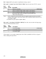
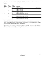
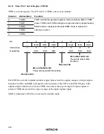
Bits 6 to 4—I/O Control B2 to B0 (IOB2 to IOB0): These bits select the GRB function.
Bit 6
IOB2
Bit 5
IOB1
Bit 4
IOB0
Function
0
0
0
GRB is an output
No output at compare match
(Initial value)
1
compare register
0 output at GRB compare match
*
1
1
0
1 output at GRB compare match
*
1
1
Output toggles at GRB compare match
(1 output in channel 2)
*
1
,
*
2
1
0
0
GRB is an input
GRB captures rising edge of input
1
capture register
GRB captures falling edge of input
1
0
GRB captures both edges of input
1
Notes: 1. After a reset, the output is 0 until the first compare match.
2. Channel 2 output cannot be toggled by compare match. This setting selects 1 output
instead.
Bit 3—Reserved: This bit cannot be modified and is always read as 1.
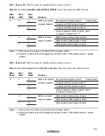
Bits 2 to 0—I/O Control A2 to A0 (IOA2 to IOA0): These bits select the GRA function.
Bit 2
IOA2
Bit 1
IOA1
Bit 0
IOA0
Function
0
0
0
GRA is an outpurt
No output at compare match
(Initial value)
1
compare register
0 output at GRA compare match
*
1
1
0
1 output at GRA compare match
*
1
1
Output toggles at GRA compare match
(1 output in channel 2)
*
1,
*
2
1
0
0
GRA is an input
GRA captures rising edge of input
1
capture register
GRA captures falling edge of input
1
0
GRA captures both edges of input
1
Notes: 1. After a reset, the output is 0 until the first compare match.
2. Channel 2 output cannot be toggled by compare match. This setting selects 1 output
instead.


