


11
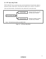
1.4 Pin Functions
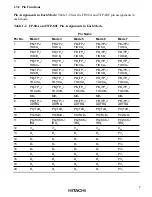
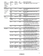
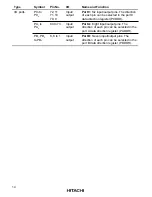
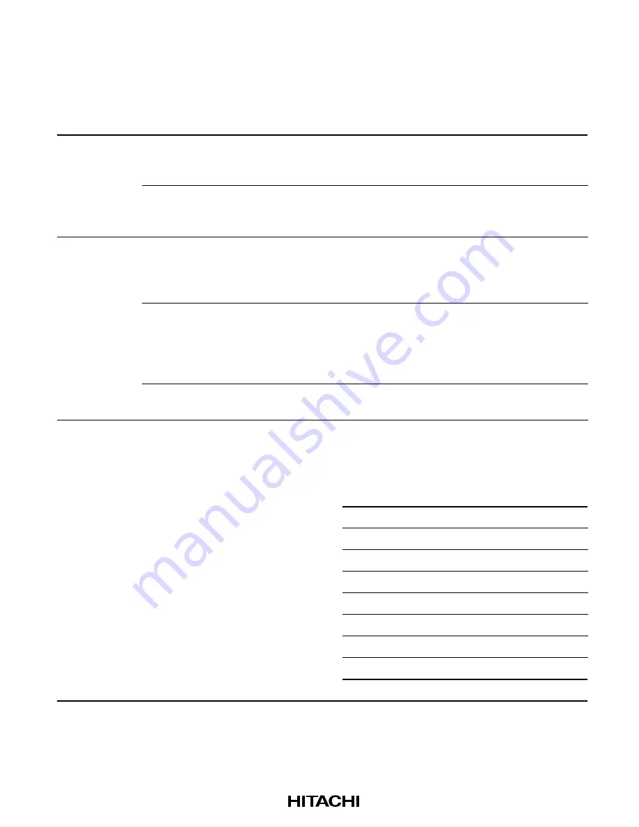
Table 1-3 summarizes the pin functions.
Table 1-3 Pin Functions
Type
Symbol
Pin No.
I/O
Name and Function
Power
V
CC
21,
53
Input
Power: For connection to the power
supply. Connect all V
CC
pins to the system
power supply.
V
SS
12,
30,
50
Input
Ground: For connection to ground (0 V).
Connect all V
SS
pins to the 0-V system
power supply.
Clock
XTAL
52
Input
For connection to a crystal resonator
For examples of crystal resonator and
external clock input, see section 16, Clock
Pulse Generator.
EXTAL
51
Input
For connection to a crystal resonator or
input of an external clock signal. For
examples of crystal resonator and external
clock input, see section 16, Clock Pulse
Generator.
ø
46
Output
System clock: Supplies the system clock
to external devices
Operating
mode
control
MD
2
,
MD
1
,
MD
0
7,
45,
44
Input
Mode 2 to mode 0: For setting the
operating mode, as follows. These pins
should not be changed during operation.
MD
2
MD
1
MD
0
Operating
Mode
0
0
0
—
0
0
1
Mode 1
0
1
0
—
0
1
1
Mode 3
1
0
0
—
1
0
1
Mode 5
1
1
0
Mode 6
1
1
1
Mode 7


