259
•
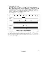
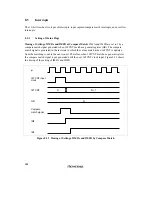
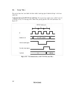
Input capture signal timing
Input capture on the rising edge, falling edge, or both edges can be selected by settings in
TIOR. Figure 8.23 shows the timing when the rising edge is selected. The pulse width of the
input capture signal must be at least 1.5 system clocks for single-edge capture, and 2.5 system
clocks for capture of both edges.
N
N
φ
Input-capture input
Input capture signal
16TCNT
GRA, GRB
Figure 8.23 Input Capture Signal Timing
8.4.3
Synchronization
The synchronization function enables two or more timer counters to be synchronized by writing
the same data to them simultaneously (synchronous preset). With appropriate 16TCR settings, two
or more timer counters can also be cleared simultaneously (synchronous clear). Synchronization
enables additional general registers to be associated with a single time base. Synchronization can
be selected for all channels (0 to 2).
Sample Setup Procedure for Synchronization: Figure 8.24 shows a sample procedure for
setting up synchronization.
Summary of Contents for H8/3060
Page 10: ......
Page 16: ......
Page 114: ...66 ...
Page 132: ...84 ...
Page 144: ...96 ...
Page 170: ...122 ...
Page 212: ...164 ...
Page 268: ...220 ...
Page 332: ...284 ...
Page 396: ...348 ...
Page 494: ...446 ...
Page 698: ...650 ...
Page 748: ...700 H8 3064F ZTAT B mask version Ports 1 2 5 LED 600 Ω Figure 22 8 Sample LED Circuit ...
Page 777: ...729 H8 3062F ZTAT B mask version Ports 1 2 5 LED 600 Ω Figure 22 14 Sample LED Circuit ...
Page 810: ...762 ...
Page 994: ...946 ...


