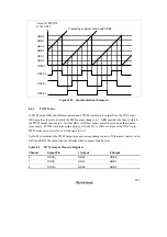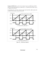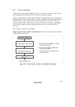
262
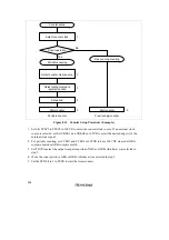
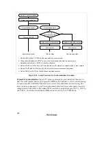
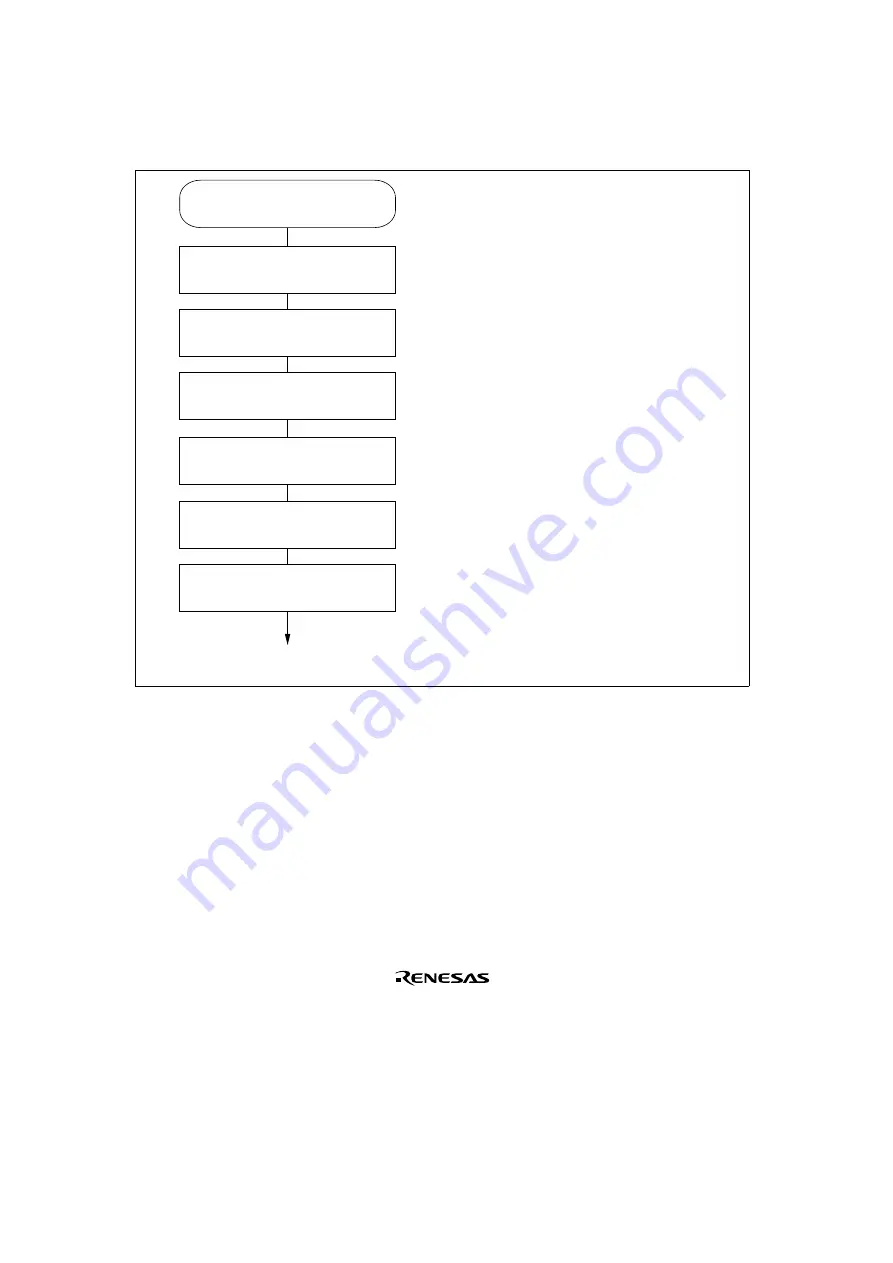
Sample Setup Procedure for PWM Mode: Figure 8.26 shows a sample procedure for setting up
PWM mode.
PWM mode
1.
2.
3.
4.
5.
6.
Set bits TPSC2 to TPSC0 in 16TCR to
select the counter clock source. If an
external clock source is selected, set
bits CKEG1 and CKEG0 in 16TCR to
select the desired edge(s) of the
external clock signal.
Set bits CCLR1 and CCLR0 in 16TCR
to select the counter clear source.
Set the time at which the PWM
waveform should go to 1 in GRA.
Set the time at which the PWM
waveform should go to 0 in GRB.
Set the PWM bit in TMDR to select
PWM mode. When PWM mode is
selected, regardless of the TIOR
contents, GRA and GRB become
output compare registers specifying
the times at which the PWM output
goes to 1 and 0. The TIOCA pin
automatically becomes the PWM
output pin. The TIOCB pin conforms
to the settings of bits IOB1 and IOB0
in TIOR. If TIOCB output is not
desired, clear both IOB1 and IOB0 to 0.
Set the STR bit to 1 in TSTR to start
the timer counter.
PWM mode
Select counter clock
1
Select counter clear source
2
Set GRA
3
Set GRB
4
Select PWM mode
5
Start counter
6
Figure 8.26 Setup Procedure for PWM Mode (Example)
Summary of Contents for H8/3060
Page 10: ......
Page 16: ......
Page 114: ...66 ...
Page 132: ...84 ...
Page 144: ...96 ...
Page 170: ...122 ...
Page 212: ...164 ...
Page 268: ...220 ...
Page 332: ...284 ...
Page 396: ...348 ...
Page 494: ...446 ...
Page 698: ...650 ...
Page 748: ...700 H8 3064F ZTAT B mask version Ports 1 2 5 LED 600 Ω Figure 22 8 Sample LED Circuit ...
Page 777: ...729 H8 3062F ZTAT B mask version Ports 1 2 5 LED 600 Ω Figure 22 14 Sample LED Circuit ...
Page 810: ...762 ...
Page 994: ...946 ...

