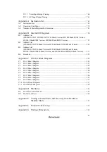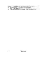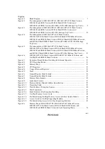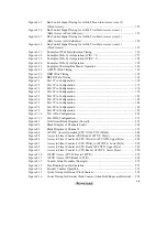
xxix
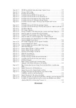
Table 11.1
WDT Pin .............................................................................................................. 350
Table 11.2
WDT Registers ..................................................................................................... 351
Table 11.3
Read Addresses of TCNT, TCSR, and RSTCSR ................................................. 356
Table 12.1
SCI Pins................................................................................................................ 364
Table 12.2
SCI Registers........................................................................................................ 365
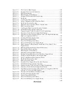
Table 12.3
Examples of Bit Rates and BRR Settings in Asynchronous Mode...................... 381
Table 12.4
Examples of Bit Rates and BRR Settings in Synchronous Mode ........................ 384
Table 12.5
Maximum Bit Rates for Various Frequencies (Asynchronous Mode) ................. 386
Table 12.6
Maximum Bit Rates with External Clock Input (Asynchronous Mode).............. 387
Table 12.7
Maximum Bit Rates with External Clock Input (Synchronous Mode) ................ 388
Table 12.8
SMR Settings and Serial Communication Formats.............................................. 390
Table 12.9
SMR and SCR Settings and SCI Clock Source Selection.................................... 390
Table 12.10
Serial Communication Formats (Asynchronous Mode)....................................... 392
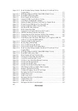
Table 12.11
Receive Error Conditions ..................................................................................... 399
Table 12.12
SCI Interrupt Sources ........................................................................................... 415
Table 12.13
SSR Status Flags and Transfer of Receive Data .................................................. 416
Table 13.1
Smart Card Interface Pins .................................................................................... 422
Table 13.2
Smart Card Interface Registers ............................................................................ 423
Table 13.3
Smart Card Interface Register Settings ................................................................ 432
Table 13.4
n-Values of CKS1 and CKS0 Settings ................................................................. 434
Table 13.5
Bit Rates (bits/s) for Various BRR Settings (When n = 0) .................................. 434
Table 13.6
BRR Settings for Typical Bit Rates (bits/s) (When n = 0) ................................... 435
Table 13.7
Maximum Bit Rates for Various Frequencies (Smart Card Interface Mode) ...... 435
Table 13.8
Smart Card Interface Mode Operating States and Interrupt Sources ................... 441
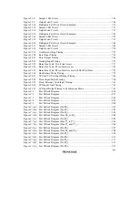
Table 14.1
A/D Converter Pins .............................................................................................. 449
Table 14.2
A/D Converter Registers ...................................................................................... 450
Table 14.3
Analog Input Channels and A/D Data Registers (ADDRA to ADDRD) ............ 451
Table 14.4
A/D Conversion Time (Single Mode) .................................................................. 461
Table 14.5
Analog Input Pin Ratings ..................................................................................... 463
Table 15.1
D/A Converter Pins .............................................................................................. 469
Table 15.2
D/A Converter Registers ...................................................................................... 469
Table 16.1
H8/3062 Series On-Chip RAM Specifications .................................................... 475
Table 16.2
System Control Register....................................................................................... 476
Table 17.1
Operating Modes and ROM ................................................................................. 479
Table 17.2
Flash Memory Pins............................................................................................... 482
Table 17.3
Flash Memory Registers....................................................................................... 482
Table 17.4
Flash Memory Erase Blocks ................................................................................ 487
Table 17.5
RAM Area Setting................................................................................................ 488
Table 17.6
On-Board Programming Mode Settings ............................................................... 490
Table 17.7
System Clock Frequencies for which Automatic Adjustment of MCU Bit Rate
is Possible ............................................................................................................. 495
Table 17.8
Hardware Protection ............................................................................................. 506
Table 17.9
Software Protection .............................................................................................. 508
Summary of Contents for H8/3060
Page 10: ......
Page 16: ......
Page 114: ...66 ...
Page 132: ...84 ...
Page 144: ...96 ...
Page 170: ...122 ...
Page 212: ...164 ...
Page 268: ...220 ...
Page 332: ...284 ...
Page 396: ...348 ...
Page 494: ...446 ...
Page 698: ...650 ...
Page 748: ...700 H8 3064F ZTAT B mask version Ports 1 2 5 LED 600 Ω Figure 22 8 Sample LED Circuit ...
Page 777: ...729 H8 3062F ZTAT B mask version Ports 1 2 5 LED 600 Ω Figure 22 14 Sample LED Circuit ...
Page 810: ...762 ...
Page 994: ...946 ...

