449
V
CC
V
CC
SBY
V
SS
PUCR1
3
PMR1
3
PDR1
3
PCR1
3
Timer G
module
TMIG
Internal data bus
P1
3
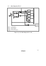
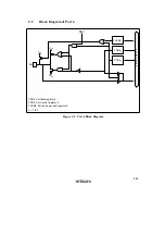
Figure C.1 (b) Port 1 Block Diagram (Pin P1
3
)
V
CC
V
CC
V
SS
PUCR1
n
PMR1
n
PDR1
n
PCR1
n
SBY
Internal data bus
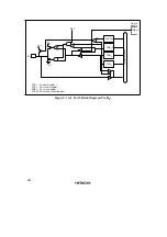
PDR1:
PCR1:
PMR1:
PUCR1:
n= 2, 1
Port data register 1
Port control register 1
Port mode register 1
Port pull-up control register 1
TMOFH (P1
2
)
TMOFL (P1
1
)
Timer F
module
P1
n
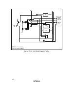
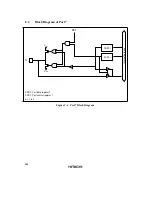
Figure C.1 (c) Port 1 Block Diagram (Pin P1
2
, P1
1
)

