background image

Hitachi 16-Bit Single-Chip Microcomputer

H8S/2678 Series

H8S/2677

HD64F2677, HD6432677

H8S/2676

HD64F2676, HD6432676

H8S/2675

HD6432675

H8S/2673

HD6432673

H8S/2670

HD6412670

Reference Manual

ADE-602-192A
Rev. 2.0
12/5/00
Hitachi, Ltd.

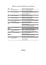
Summary of Contents for H8S/2670

Page 1: ... Single Chip Microcomputer H8S 2678 Series H8S 2677 HD64F2677 HD6432677 H8S 2676 HD64F2676 HD6432676 H8S 2675 HD6432675 H8S 2673 HD6432673 H8S 2670 HD6412670 Reference Manual ADE 602 192A Rev 2 0 12 5 00 Hitachi Ltd ...

Page 2: ... Edition March 2000 2nd Edition December 2000 Published by Electronic Devices Sales Marketing Group Semiconductor Integrated Circuits Hitachi Ltd Edited by Technical Documentation Group Hitachi Kodaira Semiconductor Co Ltd Copyright Hitachi Ltd 2000 All rights reserved Printed in Japan ...

Page 3: ...of bodily injury such as aerospace aeronautics nuclear power combustion control transportation traffic safety equipment or medical equipment for life support 4 Design your application so that the product is used within the ranges guaranteed by Hitachi particularly for maximum rating operating supply voltage range heat radiation characteristics installation conditions and other characteristics Hita...

Page 4: ...ates in Each Processing State PG5 and PG4 states amended 378 to 380 7 1 2 DC Characteristics Table 7 2 DC Characteristics Entire table amended Table 7 3 Permissible Output Currents Max values of ΣIOL and Σ IOH amended 384 7 1 3 AC Characteristics Figure 7 3 2 Oscillation Stabilization Timing added 414 Figure 7 36 WDT Output Timing amended 417 7 2 1 Absolute Maximum Ratings Table 7 11 Absolute Maxi...

Page 5: ......

Page 6: ...tion of the architecture and instruction set of the H8S 2600 CPU incorporated into H8S 2678 Series products The H8S 2678 Series Hardware Manual describes the operation of on chip functions common to H8S 2678 Series products and gives a detailed description of the related registers The H8S 2678 Series Reference Manual mainly covers information specific to H8S 2678 Series products including pin arra...

Page 7: ...A controller DMAC 7 Data transfer controller DTC 8 16 bit timer unit TPU 9 Programmable pulse generator PPG 10 8 bit timers 11 Watchdog timer 12 Serial communication interface SCI 13 Smart card interface 14 A D converter 15 D A converter 16 RAM 17 ROM flash memory 18 Clock pulse generator 19 Power down modes 20 I O ports including port block diagrams 21 Electrical characteristics 22 Register refer...

Page 8: ... Section 3 Exception Handling and Interrupt Controller H8S 2678 Series Hardware Manual 1 5 Pin Functions List Detailed descriptions 1 4 Pin Functions in Each Operating Mode Section 2 MCU Operating Modes List To find a register from its address To find register information by function Setting procedure and notes For use as design material Section 8 Registers 8 1 List of Registers Address Order 8 2 ...

Page 9: ......

Page 10: ... ROM Disabled 35 2 3 2 Mode 2 Expanded Mode with On Chip ROM Disabled 35 2 3 3 Mode 3 35 2 3 4 Mode 4 Expanded Mode with On Chip ROM Enabled 36 2 3 5 Mode 5 External ROM Activation Expanded Mode with On Chip ROM Enabled 36 2 3 6 Mode 6 External ROM Activation Expanded Mode with On Chip ROM Enabled 36 2 3 7 Mode 7 Single Chip Activation Mode with On Chip ROM Enabled 36 2 3 8 Modes 8 and 9 F ZTAT Ve...

Page 11: ...1 Interrupt Control Modes and Interrupt Operation 74 3 5 2 Interrupt Control Mode 0 77 3 5 3 Interrupt Control Mode 2 79 3 5 4 Interrupt Exception Handling Sequence 81 3 5 5 Interrupt Response Times 83 3 6 Usage Notes 84 3 6 1 Contention between Interrupt Generation and Disabling 84 3 6 2 Instructions that Disable Interrupts 85 3 6 3 Periods when Interrupts are Disabled 85 3 6 4 Interrupts during ...

Page 12: ...rface 123 4 4 1 Overview 123 4 4 2 Data Size and Data Alignment 123 4 4 3 Valid Strobes 124 4 4 4 Basic Timing 126 4 4 5 Wait Control 134 4 4 6 Read Strobe RD Timing 136 4 4 7 Extension of Chip Select CS Assertion Period 137 4 5 DRAM Interface 138 4 5 1 Overview 138 4 5 2 Setting DRAM Space 138 4 5 3 Address Multiplexing 139 4 5 4 Data Bus 139 4 5 5 Pins Used for DRAM Interface 140 4 5 6 Basic Tim...

Page 13: ...set 181 Section 5 I O Ports 183 5 1 Overview 183 5 2 Port 1 192 5 2 1 Overview 192 5 2 2 Register Configuration 193 5 2 3 Pin Functions 194 5 3 Port 2 203 5 3 1 Overview 203 5 3 2 Register Configuration 204 5 3 3 Pin Functions 205 5 4 Port 3 214 5 4 1 Overview 214 5 4 2 Register Configuration 215 5 4 3 Pin Functions 217 5 5 Port 4 220 5 5 1 Overview 220 5 5 2 Register Configuration 220 5 5 3 Pin F...

Page 14: ... 259 5 12 1 Overview 259 5 12 2 Register Configuration 260 5 12 3 Pin Functions 262 5 12 4 MOS Input Pull Up Function 263 5 13 Port D 264 5 13 1 Overview 264 5 13 2 Register Configuration 265 5 13 3 Pin Functions 267 5 13 4 MOS Input Pull Up Function 268 5 14 Port E 269 5 14 1 Overview 269 5 14 2 Register Configuration 270 5 14 3 Pin Functions 272 5 14 4 MOS Input Pull Up Function 273 5 15 Port F ...

Page 15: ...4 Port F 328 5 19 15 Port G 336 5 19 16 Port H 341 Section 6 Supporting Module Block Diagrams 345 6 1 Interrupt Controller 345 6 1 1 Features 345 6 1 2 Block Diagram 345 6 1 3 Pins 346 6 2 DMA Controller 346 6 2 1 Features 346 6 2 2 Block Diagram 347 6 2 3 Pins 348 6 3 Data Transfer Controller 348 6 3 1 Features 348 6 3 2 Block Diagram 349 6 4 EXDMA Controller EXDMAC 350 6 4 1 Features 350 6 4 2 B...

Page 16: ...11 IrDA 365 6 11 1 Features 365 6 11 2 Block Diagram 366 6 11 3 Pins 366 6 12 A D Converter 367 6 12 1 Features 367 6 12 2 Block Diagram 368 6 12 3 Pins 369 6 13 D A Converter 370 6 13 1 Features 370 6 13 2 Block Diagram 370 6 13 3 Pins 371 6 14 RAM 372 6 14 1 Features 372 6 14 2 Block Diagram 372 6 15 ROM 373 6 15 1 Features 373 6 15 2 Block Diagrams 373 6 16 Clock Pulse Generator 375 6 16 1 Feat...

Page 17: ...cs of F ZTAT Version H8S 2677 H8S 2676 417 7 2 1 Absolute Maximum Ratings 417 7 2 2 DC Characteristics 418 7 2 3 AC Characteristics 421 7 2 4 A D Conversion Characteristics 430 7 2 5 D A Conversion Characteristics 431 7 2 6 Flash Memory Characteristics 432 7 3 Usage Note 434 Section 8 Registers 435 8 1 List of Registers Address Order 435 8 2 List of Registers By Module 447 8 3 Register Description...

Page 18: ...ccess controller DMAC EXDMA controller EXDMAC and data transfer controller DTC bus masters ROM and RAM memory a16 bit timer pulse unit TPU programmable pulse generator PPG 8 bit timer module TMR watchdog timer module WDT serial communication interfaces SCI IrDA A D converter D A converter and I O ports A high functionality bus controller is also provided enabling fast and easy connection of DRAM a...

Page 19: ...iply and divide instructions Powerful bit manipulation instructions CPU operating mode Advanced mode 16 Mbyte address space Bus controller Address space divided into 8 areas with bus specifications settable independently for each area Chip select output possible for each area Selection of 8 bit or 16 bit access space for each area 2 state or 3 state access space can be designated for each area Num...

Page 20: ...U Six channel 16 bit timer on chip Pulse I O processing capability for up to 16 pins Automatic 2 phase encoder count capability Programmable pulse generator PPG Maximum 16 bit pulse output possible with TPU as time base Output trigger selectable in 4 bit groups Non overlap margin can be set Direct output or inverse output setting possible 8 bit timer 2 channels 8 bit up counter external event coun...

Page 21: ...ory Flash memory mask ROM High speed static RAM Product Name ROM RAM Bytes F ZTAT Version Mask ROM Version ROMless Version H8S 2677 384 k 8 k In planning stage In planning stage H8S 2676 256 k 8 k HD64F2676 HD6432676 H8S 2675 128 k 8 k In planning stage H8S 2673 64 k 8 k HD6432673 H8S 2670 8 k HD6412670 Interrupt controller 17 external interrupt pins NMI IRQ0 to IRQ15 56 internal interrupt sources...

Page 22: ... mode Enabled 8 bits 16 bits 13 16 bits 16 bits 14 Advanced User program mode Enabled 8 bits 16 bits 15 16 bits Selection of six MCU operating modes mask ROM version ROMless version MCU CPU External Data Bus Operating Mode Operating Mode Description On Chip ROM Initial Value Maximum Value 0 1 Advanced Expanded mode with on chip ROM Disabled 16 bits 16 bits 2 disabled 8 bits 16 bits 3 4 Advanced Ex...

Page 23: ...P12 PO10 TIOCC0 TCLKA P13 PO11 TIOCD0 TCLKB P14 PO12 TIOCA1 P15 PO13 TIOCB1 TCLKC P16 PO14 TIOCA2 EDRAK2 P17 PO15 TIOCB2 TCLKD EDRAK3 P65 TMO1 DACK1 IRQ13 P64 TMO0 DACK0 IRQ12 P63 TMCI1 TEND1 IRQ11 P62 TMCI0 TEND0 IRQ10 P61 TMRI1 DREQ1 IRQ9 P60 TMRI0 DREQ0 IRQ8 PG6 BREQ PG5 BACK PG4 BREQO PG3 CS3 PG2 CS2 PG1 CS1 PG0 CS0 PF7 ø PF6 AS PF5 RD PF4 HWR PF3 LWR PF2 LCAS IRQ15 PF1 UCAS IRQ14 PF0 WAIT ROM...

Page 24: ...NC 2 P35 SCK1 OE P34 SCK0 P33 RxD1 VSS P32 RxD0 IrRxD P31 TxD1 P30 TxD0 IrTxD P80 EDREQ2 IRQ0 P81 EDREQ3 IRQ1 P82 ETEND2 IRQ2 MD0 MD1 109 110 111 112 113 114 115 116 117 118 119 120 121 122 123 124 125 126 127 128 129 130 131 132 133 134 135 136 137 138 139 140 141 142 143 144 PD7 D15 PE0 D0 PE1 D1 PE2 D2 PE3 D3 VCC PE4 D4 PE5 D5 PE6 D6 PE7 D7 FWE 1 P61 TMRI1 DREQ1 IRQ9 P60 TMRI0 DREQ0 IRQ8 P27 PO...

Page 25: ...CK2 IRQ4 P84 EDACK2 IRQ4 P84 EDACK2 IRQ4 P84 EDACK2 IRQ4 When EXPE 1 P84 EDACK2 IRQ4 When EXPE 0 P84 IRQ4 NC 4 P85 EDACK3 IRQ5 P85 EDACK3 IRQ5 P85 EDACK3 IRQ5 P85 EDACK3 IRQ5 P85 EDACK3 IRQ5 When EXPE 1 P85 EDACK3 IRQ5 When EXPE 0 P85 IRQ5 NC 5 VCC VCC VCC VCC VCC VCC VCC 6 A0 A0 PC0 A0 A0 A0 When EXPE 1 PC0 A0 When EXPE 0 PC0 A0 7 A1 A1 PC1 A1 A1 A1 When EXPE 1 PC1 A1 When EXPE 0 PC1 A1 8 A2 A2 P...

Page 26: ... A7 When EXPE 1 PC7 A7 When EXPE 0 PC7 A7 15 A8 A8 PB0 A8 A8 A8 When EXPE 1 PB0 A8 When EXPE 0 PB0 A8 16 A9 A9 PB1 A9 A9 A9 When EXPE 1 PB1 A9 When EXPE 0 PB1 A9 17 A10 A10 PB2 A10 A10 A10 When EXPE 1 PB2 A10 When EXPE 0 PB2 A10 18 A11 A11 PB3 A11 A11 A11 When EXPE 1 PB3 A11 When EXPE 0 PB3 A11 19 VSS VSS VSS VSS VSS VSS VSS 20 A12 A12 PB4 A12 A12 A12 When EXPE 1 PB4 A12 When EXPE 0 PB4 A12 21 A13...

Page 27: ...n EXPE 0 PA0 A16 25 A17 A17 PA1 A17 A17 A17 When EXPE 1 PA1 A17 When EXPE 0 PA1 A17 26 VSS VSS VSS VSS VSS VSS VSS 27 A18 A18 PA2 A18 A18 A18 When EXPE 1 PA2 A18 When EXPE 0 PA2 A18 28 A19 A19 PA3 A19 A19 A19 When EXPE 1 PA3 A19 When EXPE 0 PA3 NC 29 A20 A20 PA4 A20 A20 A20 When EXPE 1 PA4 A20 When EXPE 0 PA4 NC 30 PA5 A21 PA5 A21 PA5 A21 PA5 A21 PA5 A21 When EXPE 1 PA5 A21 When EXPE 0 PA5 NC 31 P...

Page 28: ...D0 TEND0 P72 ETEND0 TEND0 P72 ETEND0 TEND0 When EXPE 1 P72 ETEND0 TEND0 When EXPE 0 P72 TEND0 NC 37 WDTOVF WDTOVF WDTOVF WDTOVF WDTOVF WDTOVF NC 38 NMI NMI NMI NMI NMI NMI VCC 39 VCC VCC VCC VCC VCC VCC VCC 40 P73 ETEND1 TEND1 P73 ETEND1 TEND1 P73 ETEND1 TEND1 P73 ETEND1 TEND1 P73 ETEND1 TEND1 When EXPE 1 P73 ETEND1 TEND1 When EXPE 0 P73 TEND1 NC 41 P74 EDACK0 DACK0 P74 EDACK0 DACK0 P74 EDACK0 DAC...

Page 29: ...C NC 50 P16 PO14 TIOCA2 EDRAK2 P16 PO14 TIOCA2 EDRAK2 P16 PO14 TIOCA2 EDRAK2 P16 PO14 TIOCA2 EDRAK2 P16 PO14 TIOCA2 EDRAK2 When EXPE 1 P16 PO14 TIOCA2 EDRAK2 When EXPE 0 P16 PO14 TIOCA2 NC 51 P17 PO15 TIOCB2 TCLKD EDRAK3 P17 PO15 TIOCB2 TCLKD EDRAK3 P17 PO15 TIOCB2 TCLKD EDRAK3 P17 PO15 TIOCB2 TCLKD EDRAK3 P17 PO15 TIOCB2 TCLKD EDRAK3 When EXPE 1 P17 PO15 TIOCB2 TCLKD E DRAK3 When EXPE 0 P17 PO15 ...

Page 30: ...XPE 0 P26 PO6 TIOCA5 IRQ14 NC 59 P27 PO7 TIOCB5 EDRAK1 IRQ15 P27 PO7 TIOCB5 EDRAK1 IRQ15 P27 PO7 TIOCB5 EDRAK1 IRQ15 P27 PO7 TIOCB5 EDRAK1 IRQ15 P27 PO7 TIOCB5 EDRAK1 IRQ15 When EXPE 1 P27 PO7 TIOCB5 EDRAK1 IRQ15 When EXPE 0 P27 PO7 TIOCB5 IRQ15 NC 60 P60 TMRI0 DREQ0 IRQ8 P60 TMRI0 DREQ0 IRQ8 P60 TMRI0 DREQ0 IRQ8 P60 TMRI0 DREQ0 IRQ8 P60 TMRI0 DREQ0 IRQ8 P60 TMRI0 DREQ0 IRQ8 NC 61 P61 TMRI1 DREQ1 ...

Page 31: ...E2 D2 PE2 D2 D2 PE2 D2 When EXPE 1 PE2 D2 When EXPE 0 PE2 NC 70 D1 PE1 D1 PE1 D1 D1 PE1 D1 When EXPE 1 PE1 D1 When EXPE 0 PE1 NC 71 D0 PE0 D0 PE0 D0 D0 PE0 D0 When EXPE 1 PE0 D0 When EXPE 0 PE0 NC 72 D15 D15 D15 D15 D15 When EXPE 1 D15 When EXPE 0 PD7 I O7 73 D14 D14 D14 D14 D14 When EXPE 1 D14 When EXPE 0 PD6 I O6 74 D13 D13 D13 D13 D13 When EXPE 1 D13 When EXPE 0 PD5 I O5 75 D12 D12 D12 D12 D12 ...

Page 32: ...MCI0 TEND0 IRQ10 NC 82 P63 TMCI1 TEND1 IRQ11 P63 TMCI1 TEND1 IRQ11 P63 TMCI1 TEND1 IRQ11 P63 TMCI1 TEND1 IRQ11 P63 TMCI1 TEND1 IRQ11 P63 TMCI1 TEND1 IRQ11 NC 83 P64 TMO0 DACK0 IRQ12 P64 TMO0 DACK0 IRQ12 P64 TMO0 DACK0 IRQ12 P64 TMO0 DACK0 IRQ12 P64 TMO0 DACK0 IRQ12 P64 TMO0 DACK0 IRQ12 NC 84 P65 TMO1 DACK1 IRQ13 P65 TMO1 DACK1 IRQ13 P65 TMO1 DACK1 IRQ13 P65 TMO1 DACK1 IRQ13 P65 TMO1 DACK1 IRQ13 P6...

Page 33: ... 0 PF5 NC 91 PF6 AS PF6 AS PF6 AS PF6 AS PF6 AS When EXPE 1 PF6 AS When EXPE 0 PF6 NC 92 PLLVSS PLLVSS PLLVSS PLLVSS PLLVSS PLLVSS VSS 93 RES RES RES RES RES RES RES 94 PLLVCC PLLVCC PLLVCC PLLVCC PLLVCC PLLVCC VCC 95 PF7 ø PF7 ø PF7 ø PF7 ø PF7 ø PF7 ø NC 96 VCC VCC VCC VCC VCC VCC VCC 97 EXTAL EXTAL EXTAL EXTAL EXTAL EXTAL EXTAL 98 XTAL XTAL XTAL XTAL XTAL XTAL XTAL 99 VSS VSS VSS VSS VSS VSS VS...

Page 34: ...0 TxD2 IRQ0 P50 TxD2 IRQ0 P50 TxD2 IRQ0 VSS 108 P51 RxD2 IRQ1 P51 RxD2 IRQ1 P51 RxD2 IRQ1 P51 RxD2 IRQ1 P51 RxD2 IRQ1 P51 RxD2 IRQ1 VSS 109 P52 SCK2 IRQ2 P52 SCK2 IRQ2 P52 SCK2 IRQ2 P52 SCK2 IRQ2 P52 SCK2 IRQ2 P52 SCK2 IRQ2 VCC 110 P53 ADTRG IRQ3 P53 ADTRG IRQ3 P53 ADTRG IRQ3 P53 ADTRG IRQ3 P53 ADTRG IRQ3 P53 ADTRG IRQ3 NC 111 PH2 CS6 IRQ6 PH2 CS6 IRQ6 PH2 CS6 IRQ6 PH2 CS6 IRQ6 PH2 CS6 IRQ6 When E...

Page 35: ...5 NC 125 P46 AN6 DA0 P46 AN6 DA0 P46 AN6 DA0 P46 AN6 DA0 P46 AN6 DA0 P46 AN6 DA0 NC 126 P47 AN7 DA1 P47 AN7 DA1 P47 AN7 DA1 P47 AN7 DA1 P47 AN7 DA1 P47 AN7 DA1 NC 127 P54 AN12 IRQ4 P54 AN12 IRQ4 P54 AN12 IRQ4 P54 AN12 IRQ4 P54 AN12 IRQ4 P54 AN12 IRQ4 NC 128 P55 AN13 IRQ5 P55 AN13 IRQ5 P55 AN13 IRQ5 P55 AN13 IRQ5 P55 AN13 IRQ5 P55 AN13 IRQ5 NC 129 P56 AN14 DA2 IRQ6 P56 AN14 DA2 IRQ6 P56 AN14 DA2 IR...

Page 36: ...rTxD NC 140 P80 EDREQ2 IRQ0 P80 EDREQ2 IRQ0 P80 EDREQ2 IRQ0 P80 EDREQ2 IRQ0 P80 EDREQ2 IRQ0 When EXPE 1 P80 EDREQ2 IRQ0 When EXPE 0 P80 IRQ0 NC 141 P81 EDREQ3 IRQ1 P81 EDREQ3 IRQ1 P81 EDREQ3 IRQ1 P81 EDREQ3 IRQ1 P81 EDREQ3 IRQ1 When EXPE 1 P81 EDREQ3 IRQ1 When EXPE 0 P81 IRQ1 NC 142 P82 ETEND2 IRQ2 P82 ETEND2 IRQ2 P82 ETEND2 IRQ2 P82 ETEND2 IRQ2 P82 ETEND2 IRQ2 When EXPE 1 P82 ETEND2 IRQ2 When EXP...

Page 37: ...ower supply PLLVSS 92 Input PLL ground The on chip PLL oscillator ground Clock XTAL 98 Input For connection to a crystal oscillator See section 19 Clock Pulse Generator in the H8S 2678 Series Hardware Manual for typical connection diagrams for a crystal oscillator and external clock input EXTAL 97 Input For connection to a crystal oscillator The EXTAL pin can also input an external clock See secti...

Page 38: ... System control RES 93 Input Reset input When this pin is driven low the chip is reset STBY 100 Input Standby When this pin is driven low a transition is made to hardware standby mode BREQ 115 Input Bus request Requests chip to release the bus to an external bus master BREQO 113 Output Bus request output External bus request signal used when an internal bus master accesses external space when the ...

Page 39: ...output Data bus These pins constitute a bidirectional data bus Bus control CS7 to CS0 112 111 106 to 101 Output Chip select Signals that select areas 7 to 0 AS 91 Output Address strobe When this pin is low it indicates that address output on the address bus is valid RD 90 Output Read When this pin is low it indicates that the external address space is being read HWR 89 Output High write write enab...

Page 40: ... request 1 0 These signals request DMAC activation TEND1 TEND0 TEND1 TEND0 82 81 40 36 Output DMA transfer end 1 0 These signals indicate the end of DMAC data transfer DACK1 DACK0 DACK1 DACK0 84 83 42 41 Output DMA transfer acknowledge 1 0 DMAC single address transfer acknowledge signals EXDMA controller EXDMAC EDREQ3 to EDREQ0 141 140 35 34 Input EXDMA transfer request 3 to 0 These signals reques...

Page 41: ... TIOCC3 TIOCD3 52 to 55 Input output Input capture output compare match A3 to D3 TGR3A to TGR3D input capture input output compare output PWM output pins TIOCA4 TIOCB4 56 57 Input output Input capture output compare match A4 B4 TGR4A and TGR4B input capture input output compare output PWM output pins TIOCA5 TIOCB5 58 59 Input output Input capture output compare match A5 B5 TGR5A and TGR5B input ca...

Page 42: ...15 to 12 7 to 0 Analog input pins ADTRG 110 Input A D conversion external trigger input Pin for input of an external trigger to start A D conversion D A converter DA3 DA2 DA1 DA0 130 129 126 125 Output Analog output D A converter analog output pins A D converter D A converter AVCC 122 Input The power supply pin for the A D converter and D A converter When the A D converter and D A converter are no...

Page 43: ...ut pins The direction of each input output pin can be selected in the port 5 data direction register P5DDR P65 to P60 84 to 81 61 60 Input output Port 6 Six input output pins The direction of each pin can be selected in the port 6 data direction register P6DDR P75 to P70 42 to 40 36 to 34 Input output Port 7 Six input output pins The direction of each pin can be selected in the port 7 data directi...

Page 44: ...put output pins The direction of each pin can be selected in the port E data direction register PEDDR PF7 to PF0 95 91 to 85 Input output Port F Eight input output pins The direction of each pin can be selected in the port F data direction register PFDDR PG6 to PG0 115 to 113 104 to 101 Input output Port G Seven input output pins The direction of each pin can be selected in the port G data directi...

Page 45: ...stic QFP FP 144 H8S 2673 1 Mask ROM version HD6432673 HD6432673FC 144 pin plastic QFP FP 144 H8S 2670 1 ROMless version HD6412670 HD6412670VFC 144 pin plastic QFP FP 144 Notes 1 Under development 2 In planning stage 1 7 Package Dimensions Hitachi Code JEDEC EIAJ Weight reference value FP 144G Conforms 2 4 g Unit mm Dimension including the plating thickness Base material dimension 0 10 M 20 22 0 0 ...

Page 46: ... Series F ZTAT version has twelve operating modes modes 1 2 4 to 7 and 10 to 15 that are selected by the flash write enable pin FWE and the mode pins MD2 to MD0 The input at these pins determines the CPU operating mode and the initial bus width as shown in table 2 1 Table 2 1 lists the MCU operating modes ...

Page 47: ... bits 3 1 4 1 0 0 Expanded mode with on chip ROM enabled Enabled 8 bits 16 bits 5 1 External ROM activation Enabled 16 bits 16 bits 6 1 0 expanded mode with on chip ROM enabled 8 bits 16 bits 7 1 Single chip activation mode with on chip ROM enabled Enabled 16 bits 8 1 0 0 0 9 1 10 1 0 Advanced Boot mode Enabled 8 bits 16 bits 11 1 12 1 0 0 Advanced User program Enabled 8 bits 16 bits 13 1 mode 16 ...

Page 48: ...e and single chip mode by means of the EXPE bit in the system control register SYSCR Immediately after a reset the chip starts up in single chip mode but after the start of program execution it is possible to change to externally expanded mode by setting EXPE accordingly Pin functions depend on the operating mode Modes 10 to 15 are boot modes and user program modes that allow programming and erasi...

Page 49: ...ximum of 16 Mbytes Modes 1 2 and 4 to 6 are externally expanded modes that allow access to external memory and peripheral devices The externally expanded modes allow switching between 8 bit and 16 bit bus modes After program execution starts an 8 bit or 16 bit address space can be set for each area depending on the bus controller setting If 16 bit access is selected for any one area 16 bit bus mod...

Page 50: ...ter SYSCR R W H C1 H C3 2 H FF3D Notes 1 Lower 16 bits of the address 2 Determined by pins MD2 to MD0 2 2 Register Descriptions 2 2 1 Mode Control Register MDCR Bit 7 6 5 4 3 2 1 0 MDS2 MDS1 MDS0 Initial value 0 0 0 0 0 Read Write R R R Note Determined by pins MD2 to MD0 MDCR is an 8 bit read only register that monitors the current operating mode of the H8S 2678 Series chip Bits 7 to 3 Reserved Th...

Page 51: ...e 0 Bit 3 Flash Memory Control Register Enable FLSHE Controls CPU access to the flash memory control registers FLMCR1 FLMCR2 EBR1 and EBR2 For details see section 18 ROM in the H8S 2678 Series Hardware Manual In the mask ROM and ROMless versions 0 should be written to this bit Bit 3 FLSHE Description 0 Flash memory control registers are not selected for area H FFFFC8 to H FFFFCB Initial value 1 Fl...

Page 52: ...enabled Initial value 2 3 Operating Mode Descriptions 2 3 1 Mode 1 Expanded Mode with On Chip ROM Disabled The CPU can access a 16 Mbyte address space in advanced mode The on chip ROM is disabled Ports A B and C function as an address bus ports D and E function as a data bus and parts of ports F and G carry bus control signals The initial bus mode after a reset is 16 bits with 16 bit access to all...

Page 53: ...signated for any area by the bus controller the bus mode switches to 8 bits Notes 1 H8S 2678 H 100000 to H 180000 H8S 2675 H 100000 to H 140000 2 H8S 2678 H8S 2675 H 000000 to H 100000 2 3 6 Mode 6 External ROM Activation Expanded Mode with On Chip ROM Enabled This is an external ROM activation expanded mode with on chip ROM disabled Operation is the same as in mode 5 except that the initial exter...

Page 54: ...11 Mode 12 This is a flash memory user program mode For details see section 18 ROM in the H8S 2678 Series Hardware Manual Except for flash memory erasing and programming operation is the same as in mode 4 advanced expanded mode with on chip ROM enabled 2 3 12 Modes 13 and 14 F ZTAT Version Only This is a flash memory user program mode For details see section 18 ROM in the H8S 2678 Series Hardware ...

Page 55: ... A A P A P A P A P A A A P A Port C A A P A A A P A P A P A P A A A P A Port D D D D D D P D D P D D D D P D Port E P D P D P D P D P D P D P D P D P D P D P D P D Port F PF7 PF6 P C P C P C P C P C P C P C P C P C P C P C P C PF5 PF4 C C C C C C C C C PF3 P C P C P C P C P C P C P C P C P C PF2 to PF0 P C P C P C P C P C P C P C P C P C Port G PG7 to PG1 P C P C P C P C P C P C P C P C P C P C P ...

Page 56: ...is 16 Mbytes The on chip ROM capacity is 384 kbytes in the H8S 2677 256 kbytes in the H8S 2676 128 kbytes in the H8S 2675 and 64 kbytes in the H8S 2673 the on chip RAM capacity is 8 kbytes The address space is divided into eight areas For details see section 4 Bus Controller Only advanced mode is supported in the H8S 2678 Series ...

Page 57: ...space Internal I O registers External address space Internal I O registers On chip ROM On chip RAM external address space External address space Internal I O registers External address space Internal I O registers H FFFFFF H FFFC00 H FFFF00 H FFFF20 H FFFFFF H FFFF00 H FFFF20 H 060000 External address space Note External addresses can be accessed by clearing the RAME bit in SYSCR to 0 Figure 2 1 H...

Page 58: ...n chip RAM external address space 3 External address space reserved area 2 External address space reserved area 2 Internal I O registers Internal I O registers H FFFFFF H FFFC00 H FFFF00 H FFFF20 H FFFFFF H FFFF00 H FFFF20 H 060000 H 100000 H 160000 External address space reserved area 2 On chip ROM Notes 1 External addresses can be accessed by clearing the RAME bit in SYSCR to 0 2 When EXPE 1 ext...

Page 59: ...gisters On chip ROM On chip RAM 2 External address space reserved area 1 External address space reserved area 1 Internal I O registers Internal I O registers H FFFFFF H FFFC00 H FFFF00 H FFFF20 H FFFFFF H FFFF00 H FFFF20 H 060000 H 060000 External address space reserved area 1 On chip ROM Notes 1 When EXPE 1 external address space when EXPE 0 reserved area 2 On chip RAM is used for flash memory pr...

Page 60: ...ers H FFFFFF H FFFC00 H FFFF00 H FFFF20 H FFFFFF H FFFF00 H FFFF20 H 060000 H 060000 External address space reserved area 1 On chip ROM Notes 1 When EXPE 1 external address space when EXPE 0 reserved area 2 On chip RAM is used for flash memory programming Do not clear the RAME bit in SYSCR to 0 Modes 13 and 14 external ROM activation expanded modes with on chip ROM enabled H 000000 H FFA000 H FFC0...

Page 61: ...ternal address space External address space Internal I O registers External address space Internal I O registers H FFFFFF H FFFC00 H FFFF00 H FFFF20 H FFFFFF H FFFF00 H FFFF20 H 040000 External address space Modes 1 and 2 expanded modes with on chip ROM disabled Mode 4 expanded mode with on chip ROM enabled Note External addresses can be accessed by clearing the RAME bit in SYSCR to 0 Figure 2 5 H...

Page 62: ... O registers H FFFFFF H FFFC00 H FFFF00 H FFFF20 H FFFFFF H FFFF00 H FFFF20 H 040000 H 100000 H 140000 External address space reserved area 2 On chip ROM Modes 5 and 6 external ROM activation expanded modes with on chip ROM enabled Mode 7 single chip activation expanded mode with on chip ROM enabled Notes 1 External addresses can be accessed by clearing the RAME bit in SYSCR to 0 2 When EXPE 1 ext...

Page 63: ...ternal I O registers H FFFFFF H FFFC00 H FFFF00 H FFFF20 H FFFFFF H FFFF00 H FFFF20 H 040000 H 040000 External address space reserved area 1 On chip ROM Mode 10 Boot mode expanded mode with on chip ROM enabled Mode 11 Boot mode single chip activation expanded mode with on chip ROM enabled Notes 1 When EXPE 1 external address space when EXPE 0 reserved area 2 On chip RAM is used for flash memory pr...

Page 64: ...ram mode expanded mode with on chip ROM enabled Mode 15 User program mode single chip activation expanded mode with on chip ROM enabled Notes 1 When EXPE 1 external address space when EXPE 0 reserved area 2 On chip RAM is used for flash memory programming Do not clear the RAME bit in SYSCR to 0 H 000000 H FFA000 H FFC000 External address space On chip RAM 2 External address space External address ...

Page 65: ...ternal address space External address space Internal I O registers External address space Internal I O registers H FFFFFF H FFFC00 H FFFF00 H FFFF20 H FFFFFF H FFFF00 H FFFF20 H 020000 External address space Modes 1 and 2 expanded modes with on chip ROM disabled Mode 4 expanded mode with on chip ROM enabled Note External addresses can be accessed by clearing the RAME bit in SYSCR to 0 Figure 2 9 H...

Page 66: ...O registers H FFFFFF H FFFC00 H FFFF00 H FFFF20 H FFFFFF H FFFF00 H FFFF20 H 020000 H 100000 H 120000 External address space reserved area 2 On chip ROM Modes 5 and 6 external ROM activation expanded modes with on chip ROM enabled Mode 7 single chip activation expanded mode with on chip ROM enabled Notes 1 External addresses can be accessed by clearing the RAME bit in SYSCR to 0 2 When EXPE 1 exte...

Page 67: ...ternal address space External address space Internal I O registers External address space Internal I O registers H FFFFFF H FFFC00 H FFFF00 H FFFF20 H FFFFFF H FFFF00 H FFFF20 H 010000 External address space Modes 1 and 2 expanded modes with on chip ROM disabled Mode 4 expanded mode with on chip ROM enabled Note External addresses can be accessed by clearing the RAME bit in SYSCR to 0 Figure 2 11 ...

Page 68: ...O registers H FFFFFF H FFFC00 H FFFF00 H FFFF20 H FFFFFF H FFFF00 H FFFF20 H 010000 H 100000 H 110000 External address space reserved area 2 On chip ROM Modes 5 and 6 external ROM activation expanded modes with on chip ROM enabled Mode 7 single chip activation expanded mode with on chip ROM enabled Notes 1 External addresses can be accessed by clearing the RAME bit in SYSCR to 0 2 When EXPE 1 exte...

Page 69: ...ess space Internal I O registers External address space Internal I O registers H FFFFFF H FFFC00 H FFFF00 H FFFF20 Modes 1 and 2 expanded modes with on chip ROM disabled Note External addresses can be accessed by clearing the RAME bit in SYSCR to 0 Figure 2 13 H8S 2670 Memory Map in Each Operating Mode ...

Page 70: ...ler in the H8S 2678 Series Hardware Manual Table 3 1 Exception Types and Priority Priority Exception Type Start of Exception Handling High Reset Starts after a low to high transition at the RES pin or when the watchdog timer overflows Trace 1 Starts when execution of the current instruction or exception handling ends if the trace T bit is set to 1 Interrupt Starts when execution of the current ins...

Page 71: ...NMI is assigned the highest priority level of 8 and can be accepted at all times Independent vector addresses All interrupt sources are assigned independent vector addresses making it unnecessary for the source to be identified in the interrupt handling routine Seventeen external interrupt pins NMI is the highest priority interrupt and is accepted at all times Rising edge or falling edge can be se...

Page 72: ...input unit IRQ input unit ISR ISCR ITSR IER IPR Interrupt controller Priority determination Interrupt request Vector number I I2 to I0 CCR EXR CPU Legend ISCR IRQ sense control register IER IRQ enable register ISR IRQ status register IPR Interrupt priority register INTCR Interrupt control register ITSR IRQ pin select register Figure 3 1 Block Diagram of Interrupt Controller ...

Page 73: ...pt Controller Pins Name Abbreviation I O Function Nonmaskable interrupt NMI Input Nonmaskable external interrupt rising or falling edge can be selected External interrupt request 15 to 0 IRQ15 to IRQ0 Input Maskable external interrupts rising falling or both edges or level sensing can be selected ...

Page 74: ... enable register SSIER R W H 0007 H FE18 Interrupt priority register A IPRA R W H 7777 H FE00 Interrupt priority register B IPRB R W H 7777 H FE02 Interrupt priority register C IPRC R W H 7777 H FE04 Interrupt priority register D IPRD R W H 7777 H FE06 Interrupt priority register E IPRE R W H 7777 H FE08 Interrupt priority register F IPRF R W H 7777 H FE0A Interrupt priority register G IPRG R W H ...

Page 75: ...modified Bits 5 and 4 Interrupt Control Mode 1 and 0 INTM1 INTM0 These bits select either of two interrupt control modes for the interrupt controller Bit 5 INTM1 Bit 4 INTM0 Interrupt Control Mode Description 0 0 0 Interrupts are controlled by I bit Initial value 1 Setting prohibited 1 0 2 Interrupts are controlled by bits I2 to I0 and IPR 1 Setting prohibited Bit 3 NMI Edge Select NMIEG Selects t...

Page 76: ... IPR registers are initialized to H 7777 by a reset and in hardware standby mode Bits 15 11 7 and 3 Reserved These bits are always read as 0 and cannot be modified Table 3 4 Correspondence between Interrupt Sources and IPR Settings Register Bits 14 to 12 Bits 10 to 8 Bits 6 to 4 Bits 2 to 0 IPRA IRQ0 IRQ1 IRQ2 IRQ3 IPRB IRQ4 IRQ5 IRQ6 IRQ7 IPRC IRQ8 IRQ9 IRQ10 IRQ11 IPRD IRQ12 IRQ13 IRQ14 IRQ15 IP...

Page 77: ...iority level of the interrupt is higher than the set mask level an interrupt request is issued to the CPU 3 3 3 IRQ Enable Register IER Bit 15 14 13 12 11 10 9 8 IRQ15E IRQ14E IRQ13E IRQ12E IRQ11E IRQ10E IRQ9E IRQ8E Initial value 0 0 0 0 0 0 0 0 Read Write R W R W R W R W R W R W R W R W Bit 7 6 5 4 3 2 1 0 IRQ7E IRQ6E IRQ5E IRQ4E IRQ3E IRQ2E IRQ1E IRQ0E Initial value 0 0 0 0 0 0 0 0 Read Write R ...

Page 78: ...W R W ISCRL Bit 15 14 13 12 11 10 9 8 IRQ7SCB IRQ7SCA IRQ6SCB IRQ6SCA IRQ5SCB IRQ5SCA IRQ4SCB IRQ4SCA Initial value 0 0 0 0 0 0 0 0 Read Write R W R W R W R W R W R W R W R W Bit 7 6 5 4 3 2 1 0 IRQ3SCB IRQ3SCA IRQ2SCB IRQ2SCA IRQ1SCB IRQ1SCA IRQ0SCB IRQ0SCA Initial value 0 0 0 0 0 0 0 0 Read Write R W R W R W R W R W R W R W R W The ISCR registers are two 16 bit readable writable registers that s...

Page 79: ...t 15 14 13 12 11 10 9 8 IRQ15F IRQ14F IRQ13F IRQ12F IRQ11F IRQ10F IRQ9F IRQ8F Initial value 0 0 0 0 0 0 0 0 Read Write R W R W R W R W R W R W R W R W Bit 7 6 5 4 3 2 1 0 IRQ7F IRQ6F IRQ5F IRQ4F IRQ3F IRQ2F IRQ1F IRQ0F Initial value 0 0 0 0 0 0 0 0 Read Write R W R W R W R W R W R W R W R W Note Only 0 can be written to clear the flag ISR is a 16 bit readable writable register that indicates the s...

Page 80: ...handling is executed when falling rising or both edge detection is set IRQnSCB 1 or IRQnSCA 1 When the DTC is activated by an IRQn interrupt and the DISEL bit in MRB of the DTC is 0 1 Setting conditions When IRQn input goes low when low level detection is set IRQnSCB IRQnSCA 0 When a falling edge occurs in IRQn input when falling edge detection is set IRQnSCB 0 IRQnSCA 1 When a rising edge occurs ...

Page 81: ... 16 bit readable writable register that selects input pins IRQ15 to IRQ0 ITSR is initialized to H 0000 by a reset and in hardware standby mode Bits 15 to 0 IRQ Input Pin Select ITS15 to ITS0 IRQn input pins can be used as the pins shown below according to the value of ITSn n 15 to 0 Bit ITS 0 Initial Value ITS 1 ITS15 PF2 P27 ITS14 PF1 P26 ITS13 P65 P25 ITS12 P64 P24 ITS11 P63 P23 ITS10 P62 P22 IT...

Page 82: ... W R W Bit 7 6 5 4 3 2 1 0 SSI7 SSI6 SSI5 SSI4 SSI3 SSI2 SSI1 SSI0 Initial value 0 0 0 0 0 1 1 1 Read Write R W R W R W R W R W R W R W R W SSIER is a 16 bit readable writable register that selects the IRQ pins used to recover from the software standby state SSIER is initialized to H 0007 by a reset and in hardware standby mode An IRQ interrupt used to recover from the software standby state must ...

Page 83: ...vector number for NMI interrupt exception handling is 7 IRQ15 to IRQ0 Interrupts Interrupts IRQ15 to IRQ0 are requested by an input signal at pins IRQ15 to IRQ0 Interrupts IRQ15 to IRQ0 have the following features Using ISCR it is possible to select whether an interrupt is generated by a low level falling edge rising edge or both edges at pins IRQ15 to IRQ0 Enabling or disabling of interrupt reque...

Page 84: ...rupt handling starts The IRQ pin should then be returned to the high level and IRQnF n 0 to 15 cleared in the interrupt handling routine If the IRQ pin is returned to the high level before interrupt handling is started the associated interrupt may not be executed 3 4 2 Internal Interrupts There are 56 sources for internal interrupts from on chip supporting modules 1 For each on chip supporting mod...

Page 85: ...dresses and their priority order In the default priority order smaller vector numbers have higher priority Priorities among modules can be set by means of IPR The priority order when two or more modules are set to the same priority and the priority order within a module are fixed as shown in table 3 5 ...

Page 86: ...n 8 H 0020 4 sources 9 H 0024 10 H 0028 11 H 002C Reserved for system 12 H 0030 13 H 0034 14 H 0038 IRQ0 External 16 H 0040 IPRA14 IPRA12 IRQ1 pin 17 H 0044 IPRA10 IPRA8 IRQ2 18 H 0048 IPRA6 IPRA4 IRQ3 19 H 004C IPRA2 IPRA0 IRQ4 20 H 0050 IPRB14 IPRB12 IRQ5 21 H 0054 IPRB10 IPRB8 IRQ6 22 H 0058 IPRB6 IPRB4 IRQ7 23 H 005C IPRB2 IPRB0 IRQ8 24 H 0060 IPRC14 IPRC12 IRQ9 25 H 0064 IPRC10 IPRC8 IRQ10 26...

Page 87: ... TGI0A TGR0A input capture compare match TPU channel 0 40 H 00A0 IPRF6 IPRF4 TGI0B TGR0B input capture compare match 41 H 00A4 TGI0C TGR0C input capture compare match 42 H 00A8 TGI0D TGR0D input capture compare match 43 H 00AC TCI0V overflow 0 44 H 00B0 Reserved 45 H 00B4 46 H 00B8 47 H 00BC TGI1A TGR1A input capture compare match TPU channel 1 48 H 00C0 IPRF2 IPRF0 TGI1B TGR1B input capture compa...

Page 88: ...t capture compare match TPU channel 4 64 H 0100 IPRG6 IPRG4 TGI4B TGR4B input capture compare match 65 H 0104 TCI4V overflow 4 66 H 0108 TCI4U underflow 4 67 H 010C TGI5A TGR5A input capture compare match TPU channel 5 68 H 0110 IPRG2 IPRG0 TGI5B TGR5B input capture compare match 69 H 0114 TCI5V overflow 5 70 H 0118 TCI5U underflow 5 71 H 011C CMIA0 compare match A 8 bit timer 72 H 0120 IPRH14 IPR...

Page 89: ...er end 85 H 0154 IPRI14 IPRI12 EXDMTEND2 channel 2 transfer end 86 H 0158 IPRI10 IPRI8 EXDMTEND3 channel 3 transfer end 87 H 015C IPRI6 IPRI4 ERI0 receive error 0 SCI 88 H 0160 IPRI2 IPRI0 RXI0 receive completed 0 channel 0 89 H 0164 TXI0 transmit data empty 0 90 H 0168 TEI0 transmit end 0 91 H 016C ERI1 receive error 1 SCI 92 H 0170 IPRJ14 IPRJ12 RXI1 receive completed 1 channel 1 93 H 0174 TXI1 ...

Page 90: ...A8 107 H 01AC 108 H 01B0 IPRK14 IPRK12 109 H 01B4 110 H 01B8 111 H 01BC 112 H 01C0 IPRK10 IPRK8 113 H 01C4 114 H 01C8 115 H 01CC 116 H 01D0 IPRK6 IPRK4 117 H 01D4 118 H 01D8 119 H 01DC 120 H 01E0 IPRK2 IPRK2 121 H 01E4 122 H 01E8 123 H 01EC 124 H 01F0 125 H 01F4 126 H 01F8 127 H 01FC Low Notes Interrupt sources vary depending on the model See the reference manual for the relevant model for details...

Page 91: ...its are set to 1 are controlled by the interrupt controller Table 3 6 shows the interrupt control modes The interrupt controller performs interrupt control according to the interrupt control mode set by the INTM1 and INTM0 bits in INTCR the priorities set in IPR and the masking state indicated by the I bit in the CPU s CCR and bits I2 to I0 in EXR Table 3 6 Interrupt Control Modes Interrupt INTCR ...

Page 92: ...re 3 4 Block Diagram of Interrupt Control Operation Interrupt Acceptance Control In interrupt control mode 0 interrupt acceptance control is performed by means of the I bit in CCR Table 3 7 shows the interrupts that can be selected in each interrupt control mode Table 3 7 Interrupts Selected in Each Interrupt Control Mode 1 Interrupt Mask Bit Interrupt Control Mode I Selected Interrupts 0 0 All in...

Page 93: ...generated If the same value is set for IPR acceptance of multiple interrupts is enabled and so only the interrupt source with the highest priority according to the preset default priorities is selected and has a vector number generated Interrupt sources with a lower priority than the accepted interrupt source are held pending Table 3 9 shows operations and control signal functions in each interrup...

Page 94: ...ed and other interrupt requests are held pending 3 Interrupt requests are sent to the interrupt controller the highest priority interrupt according to the priority order is selected and the others are held pending 4 When an interrupt request is accepted processing for the instruction being executed at that time is completed before interrupt exception handling is started 5 PC and CCR are saved to t...

Page 95: ...ated NMI IRQ0 IRQ1 TEI2 I 0 Save PC and CCR I 1 Read vector address Branch to interrupt service routine Yes No Yes Yes Yes No No No Yes Yes No Hold pending Figure 3 5 Flowchart of Procedure Up to Interrupt Acceptance in Interrupt Control Mode 0 ...

Page 96: ...cted 3 Next the priority of the selected interrupt request is compared with the interrupt mask level set in EXR An interrupt request with a priority no higher than the mask level set at that time is held pending and only an interrupt request with a priority higher than the interrupt mask level is accepted 4 When an interrupt request is accepted processing for the instruction being executed at that...

Page 97: ...ask level 6 or below Save PC CCR and EXR Clear T bit to 0 Update mask level Read vector address Branch to interrupt service routine Hold pending Level 1 interrupt Mask level 0 Yes Yes No Yes Yes Yes No Yes Yes No No No No No No Figure 3 6 Flowchart of Procedure Up to Interrupt Acceptance in Interrupt Control Mode 2 ...

Page 98: ...ion Handling Sequence Figure 3 7 shows the interrupt exception handling sequence The example shown is for the case where interrupt control mode 0 is set in advanced mode and the program area and stack area are in on chip memory ...

Page 99: ... read signal Internal write signal Internal data bus ø 3 1 Instruction prefetch address not executed saved PC contents return address 2 4 Instruction code not executed 3 Instruction prefetch address not executed 5 SP 2 7 SP 4 6 8 Saved PC and saved CCR 9 11 Vector address 10 12 Interrupt service routine start address vector address contents 13 Interrupt service routine start address 13 10 12 14 Fi...

Page 100: ...ruction ends 2 1 to 19 2 SI 1 to 19 2 SI 3 Saving PC CCR EXR to stack 2 SK 3 SK 4 Vector fetch 2 SI 2 SI 5 Instruction fetch 3 2 SI 2 SI 6 Internal processing 4 2 2 Total using on chip memory 12 to 32 13 to 33 Notes 1 Two states in case of internal interrupt 2 Refers to MULXS and DIVXS instructions 3 Prefetch after interrupt acceptance and interrupt service routine prefetch 4 Internal processing a...

Page 101: ...ompletion of the instruction However if there is an interrupt request of higher priority than that interrupt interrupt exception handling will be executed for the higher priority interrupt and the lower priority interrupt will be ignored The same also applies when an interrupt source flag is cleared to 0 Figure 3 8 shows an example in which the TGIEA bit in the TPU s TIER0 register is cleared to 0...

Page 102: ... EEPMOV Instruction The EEPMOV B instruction and EEPMOV W instruction differ in their reaction to interrupt requests With the EEPMOV B instruction an interrupt request including NMI issued during the transfer is not accepted until the transfer is completed With the EEPMOV W instruction if an interrupt request is issued during the transfer interrupt exception handling starts at a break in the trans...

Page 103: ...anual 3 7 2 Block Diagram Figure 3 9 shows a block diagram of the DTC DMAC and interrupt controller DMAC Selection circuit DTCER DTVECR Control logic Priority determination CPU DTC Select signal IRQ interrupt On chip supporting module Clear signal Interrupt controller I I2 to I0 DTC activation request vector number CPU interrupt request vector number SWDTE clear signal Clear signal Interrupt sourc...

Page 104: ...rformed the specified number of data transfers and the transfer counter value is 0 following the DTC data transfer the DTCE bit is cleared to 0 and an interrupt request is sent to the CPU Determination of Priority The DTC activation source is selected in accordance with the default priority order and is not affected by mask or priority levels Priorities are shown in table 3 12 With the DMAC the ac...

Page 105: ... 26 H 0434 DTCEB5 IRQ11 27 H 0436 DTCEB4 IRQ12 28 H 0438 DTCEB3 IRQ13 29 H 043A DTCEB2 IRQ14 30 H 043C DTCEB1 IRQ15 31 H 043E DTCEB0 ADI A D conversion end A D 38 H 044C DTCEC6 TGI0A TGR0A compare match input capture TPU channel 0 40 H 0450 DTCEC5 TGI0B TGR0B compare match input capture 41 H 0452 DTCEC4 TGI0C TGR0C compare match input capture 42 H 0454 DTCEC3 TGI0D TGR0D compare match input captur...

Page 106: ...ompare match B 73 H 0492 DTCEE2 CMI1A compare match A 8 bit timer channel 1 76 H 0498 DTCEE1 CMI1B compare match B 77 H 049A DTCEE0 DMTEND0A channel 0 channel 0A transfer end DMAC 80 H 04A0 DTCEF7 DMTEND0B channel 0B transfer end 81 H 04A2 DTCEF6 DMTEND1A channel 1 channel 1A transfer end 82 H 04A4 DTCEF5 DMTEND1B channel 1B transfer end 83 H 04A6 DTCEF4 RXI0 receive completed 0 SCI channel 0 89 H...

Page 107: ...is used Interrupt source clearing is performed The CPU should clear the source flag in the interrupt service routine The relevant interrupt is used The interrupt source is not cleared X The relevant bit cannot be used Don t care Usage Note SCI and A D converter interrupt sources are cleared when the DMAC or DTC reads or writes to the prescribed register and are not dependent on the DTA and DISEL b...

Page 108: ...ions can be set independently for each area 8 bit access or 16 bit access can be selected for each area DRAM and burst ROM interfaces can be set Basic bus interface Chip select signals CS0 to CS7 can be output for areas 0 to 7 2 state access or 3 state access can be selected for each area Program wait states can be inserted for each area CS assertion period extension states can be inserted for eac...

Page 109: ...ernal write cycle and internal access can be executed in parallel DMAC single address mode and internal access can be executed in parallel Bus arbitration function Includes a bus arbiter that arbitrates bus mastership between the CPU DMAC DTC and EXDMAC Other features Refresh counter refresh timer can be used as an interval timer External bus release function EXDMAC external bus transfer and inter...

Page 110: ...ternal bus controller Internal bus master bus request signal EXDMAC bus request signal Internal bus master bus acknowledge signal EXDMAC bus acknowledge signal CPU bus request signal DTC bus request signal DMAC bus request signal CPU bus acknowledge signal DTC bus acknowledge signal DMAC bus acknowledge signal ABWCR ASTCR WTCRAH WTCRAL WTCRBH WTCRBL RDNCR DRAMCRH DRAMCRL DRACCR REFCRH REFCRL RTCNT...

Page 111: ...nal indicating that basic bus interface space is being written to and lower half D7 to D0 of data bus is enabled Chip select 0 CS0 Output Strobe signal indicating that area 0 is selected Chip select 1 CS1 Output Strobe signal indicating that area 1 is selected Chip select 2 row address strobe 2 CS2 Output Strobe signal indicating that area 2 is selected DRAM row address strobe signal when area 2 i...

Page 112: ...vice Bus request acknowledge BACK Output Acknowledge signal indicating that bus has been released Bus request output BREQO Output External bus request signal used when internal bus master accesses external space when external bus is released Data transfer acknowledge 1 DMAC DACK1 Output Data transfer acknowledge signal for single address transfer by DMAC channel 1 Data transfer acknowledge 0 DMAC ...

Page 113: ...robe timing control register RDNCR R W H 00 H FEC6 8 Chip select assertion period control CSACRH R W H 00 H FEC8 8 registers CSACRL R W H 00 H FEC9 8 Burst ROM interface control registers BROMCRH R W H 00 H FECA 8 BROMCRL R W H 00 H FECB 8 Bus control register BCR R W H 1C00 H FECC 16 DRAM control register DRAMCR R W H 0000 H FED0 16 DRAM access control register DRACCR R W H 00 H FED2 8 Refresh co...

Page 114: ...ngs in ABWCR After a reset and in hardware standby mode ABWCR is initialized to H FF in modes 2 4 and 6 and to H 00 in modes 1 5 and 7 It is not initialized in software standby mode Bits 7 to 0 Area 7 to 0 Bus Width Control ABW7 to ABW0 These bits select whether the corresponding area is to be designated as 8 bit access space or 16 bit access space Bit n ABWn Description 0 Area n is designated as ...

Page 115: ... Wait state insertion in area n external space access is disabled 1 Area n is designated as 3 state access space Initial value Wait state insertion in area n external space access is enabled n 7 to 0 4 2 3 Wait Control Registers A and B WTCRA WTCRB WTCRA and WTCRB are 16 bit readable writable registers that select the number of program wait states for each area Program waits are not inserted in on...

Page 116: ... access 1 1 program wait state inserted in area n external access 1 0 2 program wait states inserted in area n external access 1 3 program wait states inserted in area n external access 1 0 0 4 program wait states inserted in area n external access 1 5 program wait states inserted in area n external access 1 0 6 program wait states inserted in area n external access 1 7 program wait states inserte...

Page 117: ...data setup and hold time specifications are also one half state earlier The read strobe is negated one half state earlier regardless of 2 state or 3 state access designation or the number of program waits Bit 7 to 0 RDNn Description 0 In an area n read access the RD strobe is negated at the end of the read cycle Initial value 1 In an area n read access the RD strobe is negated one half state befor...

Page 118: ...0 0 0 0 0 0 0 0 Read Write R W R W R W R W R W R W R W R W CSACRH and CSACRL are 8 bit readable writable registers that specify whether or not the assertion period of the basic bus interface chip select signals CSn and address signals is to be extended Extending the assertion period of the CSn and address signals allows flexible interfacing to external I O devices CSACRH and CSACRL are initialized...

Page 119: ...lue 1 In area n basic bus interface access the CSn and address assertion period Th is extended n 7 to 0 CSACRL Bits 7 to 0 CS and Address Signal Assertion Period Control 2 CSXT7 to CSXT0 These bits specify whether or not the Tt cycle shown in figure 4 3 is to be inserted When an area for which the CSXTn bit is set to 1 is accessed a Tt state in which only the CSn and address signals are asserted i...

Page 120: ...Area 0 Burst ROM I F Control Register BROMCRH Area 1 Burst ROM I F Control Register BROMCRL BROMCRH Bit 7 6 5 4 3 2 1 0 BSRM0 BSTS02 BSTS01 BSTS00 BSWD01 BSWD00 Initial value 0 0 0 0 0 0 0 0 Read Write R W R W R W R W R W R W R W R W BROMCRL Bit 7 6 5 4 3 2 1 0 BSRM1 BSTS12 BSTS11 BSTS10 BSWD11 BSWD10 Initial value 0 0 0 0 0 0 0 0 Read Write R W R W R W R W R W R W R W R W ...

Page 121: ... n 1 or 0 Bits 6 to 4 Burst Cycle Select BSTSn2 BSTSn1 BSTSn0 These bits select the number of burst cycle states Bit 6 BSTSn2 Bit 5 BSTSn1 Bit 4 BSTSn0 Description 0 0 0 Area n burst cycle comprises 1 state Initial value 1 Area n burst cycle comprises 2 states 1 0 Area n burst cycle comprises 3 states 1 Area n burst cycle comprises 4 states 1 0 0 Area n burst cycle comprises 5 states 1 Area n burs...

Page 122: ...er used for idle cycle settings selection of the external bus released state protocol enabling or disabling of the write data buffer function and enabling or disabling of WAIT pin input BCR is initialized to H 1C00 by a reset and in hardware standby mode It is not initialized in software standby mode Bit 15 External Bus Release Enable BRLE Enables or disables external bus release by means of the B...

Page 123: ...ycles When this bit is set to 1 an idle cycle is inserted in the case of consecutive external read cycles in different areas Bit 11 ICIS1 Description 0 Idle cycle not inserted in case of consecutive external read cycles in different areas 1 Idle cycle inserted in case of consecutive external read cycles in different areas Initial value Bit 10 Idle Cycle Insert 0 ICIS0 When an external read cycle a...

Page 124: ...ble writable bits but the write value should always be 0 4 2 8 DRAM Control Register DRAMCR Bit 15 14 13 12 11 10 9 8 OEE RAST CAST RMTS2 RMTS1 RMTS0 Initial value 0 0 0 0 0 0 0 0 Read Write R W R W R W R W R W R W R W R W Bit 7 6 5 4 3 2 1 0 BE RCDM DDS EDDS MXC2 MXC1 MXC0 Initial value 0 0 0 0 0 0 0 0 Read Write R W R W R W R W R W R W R W R W DRAMCR is a 16 bit readable writable register used t...

Page 125: ...tionship between the RAST bit setting and the RAS assertion timing The setting of this bit applies to all areas designated as DRAM space Bit 14 RAST Description 0 RAS is asserted from ø falling edge in Tr cycle Initial value 1 RAS is asserted from start of Tr cycle Tp Address RAST 0 RAS RAST 1 RAS Tr Tc1 Tc2 UCAS LCAS Bus cycle Row address Column address Figure 4 4 RAS Signal Assertion Timing 2 St...

Page 126: ...ut from the RAS2 pin Bit 10 Bit 9 Bit 8 Description RMTS2 RMTS 1 RMTS 0 Area 5 Area 4 Area 3 Area 2 0 0 0 Normal space Normal space Normal space Normal space 1 Normal space Normal space Normal space DRAM space 1 0 Normal space Normal space DRAM space DRAM space 1 DRAM space DRAM space DRAM space DRAM space 1 0 Reserved Reserved Reserved Reserved 1 0 setting prohibited setting prohibited setting pr...

Page 127: ...med on the DRAM interface When the BE bit is cleared to 0 in DRAMCR disabling DRAM burst access DMAC single address transfer is performed in full access mode regardless of the setting of the DDS bit This bit has no effect on other bus master external accesses or DMAC dual address transfers Bit 5 DDS Description 0 Full access is always executed when DMAC single address transfer is performed in DRAM...

Page 128: ... Bit 0 MXC0 Description 0 0 0 8 bit shift Initial value When 8 bit access space is designated Row address bits A23 to A8 used for comparison When 16 bit access space is designated Row address bits A23 to A9 used for comparison 1 9 bit shift When 8 bit access space is designated Row address bits A23 to A9 used for comparison When 16 bit access space is designated Row address bits A23 to A10 used fo...

Page 129: ... of number of states etc comply with settings of bits ICIS1 ICIS0 and IDLC in BCR register Bit 6 Reserved This is a readable writable bit but the write value should always be 0 Bits 5 and 4 Precharge State Control TPC1 TPC0 These bits select the number of states in the RAS precharge cycle in normal access and refreshing From 1 to 4 states can be set for the precharge cycle Bit 5 TPC1 Bit 4 TPC0 De...

Page 130: ...RTCK2 RTCK1 RTCK0 Initial value 0 0 0 0 0 0 0 0 Read Write R W R W R W R W R W R W R W R W Bit 7 6 5 4 3 2 1 0 RFSHE CBRM RLW1 RLW0 SLFRF TPCS2 TPCS1 TPCS0 Initial value 0 0 0 0 0 0 0 0 Read Write R W R W R W R W R W R W R W R W Note Only 0 can be written to clear the flag REFCR is a 16 bit readable writable register that specifies DRAM interface refresh control REFCR is initialized to H 0000 by a...

Page 131: ...d Bits 13 and 12 CAS RAS Wait Control RCW1 RCW0 These bits select whether or not a wait cycle is to be inserted between the CAS assert cycle and RAS assert cycle in a DRAM refresh cycle A 1 to 3 state wait cycle can be inserted Bit 13 RCW1 Bit 12 RCW0 Description 0 0 Wait state not inserted between CAS and RAS in refresh cycle Initial value 1 1 wait state inserted between CAS and RAS in refresh cy...

Page 132: ...CBRM Allows selection of CBR refreshing performed in parallel with other external accesses or execution of CBR refreshing alone Bit 6 CBRM Description 0 External access during CAS before RAS refreshing is enabled Initial value 1 External access during CAS before RAS refreshing is disabled Bits 5 and 4 Refresh Cycle Wait Control RLW1 RLW0 These bits select the number of wait states to be inserted i...

Page 133: ...y after self refreshing The number of states in the precharge cycle immediately after self refreshing are added to the number of states set by bits TPC1 and TPC0 in the DRACCR register Bit 2 TPCS2 Bit 1 TPCS1 Bit 0 TPCS0 Description 0 0 0 RAS precharge cycle after self refresh TPC set value states Initial value 1 RAS precharge cycle after self refresh TPC set value 1 states 1 0 RAS precharge cycle...

Page 134: ... CMIE bit in REFCR is set to 1 a compare match interrupt CMI is generated RTCNT is initialized to H 00 by a reset and in hardware standby mode It is not initialized in software standby mode 4 2 12 Refresh Time Control Register RTCOR Bit 7 6 5 4 3 2 1 0 Initial value 1 1 1 1 1 1 1 1 Read Write R W R W R W R W R W R W R W R W RTCOR is an 8 bit readable writable register that sets the period for comp...

Page 135: ...e 4 5 shows an outline of the memory map Chip select signals CS0 to CS7 can be output for each area Area 0 2 Mbytes H 000000 H FFFFFF H 1FFFFF H 200000 Area 1 2 Mbytes H 3FFFFF H 400000 Area 2 2 Mbytes H 5FFFFF H 600000 Area 3 2 Mbytes H 7FFFFF H 800000 Area 4 2 Mbytes H 9FFFFF H A00000 Area 5 2 Mbytes H BFFFFF H C00000 Area 6 2 Mbytes H DFFFFF H E00000 Area 7 2 Mbytes Advanced mode Figure 4 5 Are...

Page 136: ...et Number of Access States Two or three access states can be selected with ASTCR An area for which 2 state access is selected functions as a 2 state access space and an area for which 3 state access is selected functions as a 3 state access space With the DRAM interface and burst ROM interface the number of access states may be determined without regard to ASTCR When 2 state access space is design...

Page 137: ...Select CS Assertion Period Extension States Some external I O devices require a setup time and hold time between address and CS signals and strobe signals such as RD HWR and LWR Settings can be made in the CSACR registers to insert states in which only the CS AS and address signals are asserted before and after a basic bus space access cycle 4 3 3 Memory Interfaces The memory interfaces of the H8S...

Page 138: ...l space When area 1 external space is accessed the CS1 signal can be output Either basic bus interface or burst ROM interface can be selected for area 1 Areas 2 to 5 In externally expanded mode areas 2 to 5 are all external space When area 2 to 5 external space is accessed signals CS2 to CS5 can be output Basic bus interface or DRAM interface can be selected for areas 2 to 5 With the DRAM interfac...

Page 139: ...onding to the particular CSn pin In expanded mode with on chip ROM disabled the CS0 pin is placed in the output state after a reset Pins CS1 to CS7 are placed in the input state after a reset and so the corresponding DDR bits should be set to 1 when outputting signals CS1 to CS7 In expanded mode with on chip ROM enabled pins CS0 to CS7 are all placed in the input state after a reset and so the cor...

Page 140: ...0 is used according to the bus specifications for the area being accessed 8 bit access space or 16 bit access space and the data size 8 Bit Access Space Figure 4 7 illustrates data alignment control for the 8 bit access space With the 8 bit access space the upper data bus D15 to D8 is always used for accesses The amount of data that can be accessed at one time is one byte a word access is performe...

Page 141: ...er the address is even or odd The upper data bus is used for an even address and the lower data bus for an odd address D15 D8 D7 D0 Upper data bus Lower data bus Byte size Word size 1st bus cycle 2nd bus cycle Longword size Even address Byte size Odd address Figure 4 8 Access Sizes and Data Alignment Control 16 bit Access Space 4 4 3 Valid Strobes Table 4 4 shows the data buses used and valid stro...

Page 142: ...Lower Data Bus D7 to D0 8 bit access Byte Read RD Valid Invalid space Write HWR Hi Z 16 bit access Byte Read Even RD Valid Invalid space Odd Invalid Valid Write Even HWR Valid Hi Z Odd LWR Hi Z Valid Word Read RD Valid Valid Write HWR LWR Valid Valid Note Hi Z High impedance state Invalid Input state input value is ignored ...

Page 143: ...ce is accessed the upper half D15 to D8 of the data bus is used The LWR pin is fixed high Wait states cannot be inserted Bus cycle T1 T2 Address bus ø CSn AS RD D15 to D8 Valid D7 to D0 Invalid Read HWR LWR D15 to D8 Valid D7 to D0 High impedance Write High Notes 1 n 0 to 7 2 When RDNn 0 Figure 4 9 Bus Timing for 8 Bit 2 State Access Space ...

Page 144: ...essed the upper half D15 to D8 of the data bus is used The LWR pin is fixed high Wait states can be inserted Bus cycle T1 T2 Address bus ø CSn AS RD D15 to D8 Valid D7 to D0 Invalid Read HWR LWR D15 to D8 Valid D7 to D0 Write High T3 High impedance Notes 1 n 0 to 7 2 When RDNn 0 Figure 4 10 Bus Timing for 8 Bit 3 State Access Space ...

Page 145: ...of the data bus is used for odd addresses and the lower half D7 to D0 for even addresses Wait states cannot be inserted Bus cycle T1 T2 Address bus ø CSn AS RD D15 to D8 Valid D7 to D0 Invalid Read HWR LWR D15 to D8 Valid D7 to D0 Write High High impedance Notes 1 n 0 to 7 2 When RDNn 0 Figure 4 11 Bus Timing for 16 Bit 2 State Access Space 1 Even Address Byte Access ...

Page 146: ...ss bus ø CSn AS RD D15 to D8 Invalid D7 to D0 Valid Read HWR LWR D15 to D8 D7 to D0 Valid Write High High impedance Notes 1 n 0 to 7 2 When RDNn 0 Figure 4 12 Bus Timing for 16 Bit 2 State Access Space 2 Odd Address Byte Access ...

Page 147: ...le T1 T2 Address bus ø CSn AS RD D15 to D8 Valid D7 to D0 Valid Read HWR LWR D15 to D8 Valid D7 to D0 Valid Write Notes 1 n 0 to 7 2 When RDNn 0 Figure 4 13 Bus Timing for 16 Bit 2 State Access Space 3 Word Access ...

Page 148: ... the data bus is used for the odd address and the lower half D7 to D0 for the even address Wait states can be inserted Bus cycle T1 T2 Address bus ø CSn AS RD D15 to D8 Valid D7 to D0 Invalid Read HWR LWR D15 to D8 Valid D7 to D0 Write High T3 High impedance Notes 1 n 0 to 7 2 When RDNn 0 Figure 4 14 Bus Timing for 16 Bit 3 State Access Space 1 Even Address Byte Access ...

Page 149: ... bus ø CSn AS RD D15 to D8 Invalid D7 to D0 Valid Read HWR LWR D15 to D8 D7 to D0 Valid Write High T3 High impedance Notes 1 n 0 to 7 2 When RDNn 0 Figure 4 15 Bus Timing for 16 Bit 3 State Access Space 2 Odd Address Byte Access ...

Page 150: ... T1 T2 Address bus ø CSn AS RD D15 to D8 Valid D7 to D0 Valid Read HWR LWR D15 to D8 Valid D7 to D0 Valid Write T3 Notes 1 n 0 to 7 2 When RDNn 0 Figure 4 16 Bus Timing for 16 Bit 3 State Access Space 3 Word Access ...

Page 151: ... and WTCRB Pin Wait Insertion Setting the WAITE bit to 1 in BCR enables wait input by means of the WAIT pin When external space is accessed in this state a program wait is first inserted in accordance with the settings in WTCRA and WTCRB If the WAIT pin is low at the falling edge of ø in the last T2 or Tw state another Tw state is inserted If the WAITpin is held low Tw states are inserted until it...

Page 152: ...ta Write WAIT Data bus T2 Tw Tw Tw T3 By WAIT pin Notes 1 Downward arrows indicate the timing of WAIT pin sampling 2 When RDNn 0 Figure 4 17 Example of Wait State Insertion Timing The settings after a reset are 3 state access insertion of 7 program wait states and WAIT input disabled ...

Page 153: ...e note that if the read strobe timing is changed by setting RDNn to 1 the RD timing will change relative to the rise of DACK or EDACK Figure 4 18 shows an example of the timing when the read strobe timing is changed in basic bus 3 state access space Bus cycle T1 T2 Address bus ø CSn AS RD T3 Data bus RD DACK EDACK Data bus RDNn 0 RDNn 1 Figure 4 18 Example of Read Strobe Timing ...

Page 154: ...ingent since the write data is output to the data bus Figure 4 19 shows an example of the timing when the CS assertion period is extended in basic bus 3 state access space Th Address bus ø T1 T2 T3 Tt Bus cycle Data bus HWR LWR Write Data bus RD CSn AS Read when RDNn 0 Read data Write data Figure 4 19 Example of Timing when Chip Select Assertion Period is Extended Both extension state Th inserted ...

Page 155: ...e 4 5 Possible DRAM space settings are one area area 2 two areas areas 2 and 3 four areas areas 2 to 5 and continuous area areas 2 to 5 Table 4 5 DRAM Space Settings by Bits RMTS2 to RMTS0 RMTS2 RMTS1 RMTS0 Area 5 Area 4 Area 3 Area 2 0 0 1 Normal space Normal space Normal space DRAM space 1 0 Normal space Normal space DRAM space DRAM space 1 DRAM space DRAM space DRAM space DRAM space 1 0 Reserve...

Page 156: ... 0 10 bits A23 to A16 A15 A14 A23 A22 A21 A20 A19 A18 A17 A16 A15 A14 A13 A12 A11 A10 1 11 bits A23 to A16 A15 A14 A13 A23 A22 A21 A20 A19 A18 A17 A16 A15 A14 A13 A12 A11 1 Reserved setting prohibited Column address A23 to A16 A15 A14 A13 A12 A11 A10 A9 A8 A7 A6 A5 A4 A3 A2 A1 A0 4 5 4 Data Bus If a bit in ABWCR corresponding to an area designated as DRAM space is set to 1 that area is designated ...

Page 157: ...e CS4 RAS4 Row address strobe 4 Output Row address strobe when area 4 is designated as DRAM space CS5 RAS5 Row address strobe 5 Output Row address strobe when area 5 is designated as DRAM space UCAS UCAS Upper column address strobe Output Upper column address strobe for 16 bit DRAM space access Column address strobe for 8 bit DRAM space access LCAS LCAS Lower column address strobe Output Lower col...

Page 158: ...s WE HWR OE RD Data bus Address bus Tr Tc1 Tc2 Row address High High Column address Note n 2 to 5 Figure 4 20 DRAM Basic Access Timing RAST 0 CAST 0 When DRAM space is accessed the RD signal is output as the OE signal for DRAM When connecting DRAM provided with an EDO page mode the OE signal should be connected to the OE pin of the DRAM Setting the OEE bit to 1 in the DRAMCR register enables the O...

Page 159: ... register Use the setting that gives the optimum specification values CAS pulse width etc according to the DRAM connected and the operating frequency of the chip Figure 4 21 shows an example of the timing when a 3 state column address output cycle is selected Tp ø RASn CSn Read Write UCAS LCAS WE HWR OE RD Data bus WE HWR OE RD Data bus Address bus Tr Tc1 Tc2 Tc3 Row address Column address High Hi...

Page 160: ...gnal Use the optimum setting according to the DRAM connected and the operating frequency of the chip Figure 4 22 shows an example of the timing when the RAS signal goes low from the beginning of the Tr state Tp ø RASn CSn Read Write UCAS LCAS WE HWR OE RD Data bus WE HWR OE RD Data bus Address bus Tr Tc1 Tc2 Row address Column address High High Note n 2 to 5 Figure 4 22 Example of Access Timing wh...

Page 161: ...address is output Use the setting that gives the optimum row address signal hold time relative to the fall of the RAS signal according to the DRAM connected and the operating frequency of the chip Figure 4 23 shows an example of the timing when one Trw state is set Tp ø RASn CSn Read Write UCAS LCAS WE HWR OE RD Data bus WE HWR OE RD Data bus Address bus Tr Trw Tc1 Tc2 Row address Column address H...

Page 162: ...ptimum number of Tp cycles according to the DRAM connected and the operating frequency of the chip Figure 4 24 shows the timing when two Tp states are inserted The setting of bits TPC1 and TPC0 is also valid for Tp states in refresh cycles Tp1 ø RASn CSn Read Write UCAS LCAS WE HWR OE RD Data bus WE HWR OE RD Data bus Address bus Tp2 Tr Tc1 Tc2 Row address Column address High High Note n 2 to 5 Fi...

Page 163: ...7 wait states can be inserted automatically between the Tc1 state and Tc2 state according to the settings in registers WTCRA and WTCRB Pin Wait Insertion When the WAITE bit in the BCR register is set to 1 and the ASTCR bit is set to 1 wait input by means of the WAIT pin is enabled When DRAM space is accessed in this state a program wait Tw is first inserted If the WAIT pin is low at the falling ed...

Page 164: ...ASn CSn Read Write UCAS LCAS UCAS LCAS WE HWR OE RD Data bus WE HWR OE RD Data bus Row address Column address High High Note Downward arrows indicate the timing of WAIT pin sampling n 2 to 5 Figure 4 25 Example of Wait State Insertion Timing 1 2 State Column Address Output ...

Page 165: ... RASn CSn Read Write UCAS LCAS UCAS LCAS WE HWR OE RD Data bus WE HWR OE RD Data bus Row address Column address High High Note Downward arrows indicate the timing of WAIT pin sampling n 2 to 5 Figure 4 26 Example of Wait State Insertion Timing 2 3 State Column Address Output ...

Page 166: ...e access Figure 4 27 shows the control timing for 2 CAS access and figure 4 28 shows an example of 2 CAS DRAM connection Tp High Z ø RASn CSn UCAS LCAS WE HWR OE RD Upper data bus Lower data bus Address bus Tr Tc1 Tc2 Note n 2 to 5 Row address Column address Write data High High Figure 4 27 2 CAS Control Timing Upper Byte Write Access RAST 0 CAST 0 ...

Page 167: ...ss for each access a fast page mode is also provided which can be used when making consecutive accesses to the same row address This mode enables fast burst access of data by simply changing the column address after the row address has been output Burst access can be selected by setting the BE bit to 1 in DRAMCR Burst Access Fast Page Mode Operation Timing Figures 4 29 and 4 30 show the operation ...

Page 168: ...1 Tc2 RASn CSn Read Write UCAS LCAS WE HWR OE RD Data bus WE HWR OE RD Data bus Address bus Note n 2 to 5 Row address Column address 1 Column address 2 High High Figure 4 29 Operation Timing in Fast Page Mode 1 RAST 0 CAST 0 ...

Page 169: ... by access to another space In this case if the RAS signal is held low during the access to the other space burst operation can be resumed when the same row address in DRAM space is accessed again RAS Down Mode To select RAS down mode set both the RCDM bit and the BE bit to 1 in DRAMCR If access to DRAM space is interrupted and another space is accessed the RAS signal is held low during the access...

Page 170: ...space read Tp Tr Tc1 Tc2 T1 T2 DRAM space read Tc1 Tc2 Note n 2 to 5 ø RASn CSn UCAS LCAS RD OE Data bus Address bus Row address Column address 1 Column address 2 External address Figure 4 31 Example of Operation Timing in RAS Down Mode RAST 0 CAST 0 RAS Up Mode To select RAS up mode clear the RCDM bit to 0 in DRAMCR Each time access to DRAM space is interrupted and another space is accessed the R...

Page 171: ...g is used In addition self refreshing can be executed when the chip enters the software standby state Refresh control is enabled when any area is designated as DRAM space in accordance with the setting of bits RMTS2 to RMTS0 in the DRAMCR register CAS before RAS CBR Refreshing To select CBR refreshing set the RFSHE bit to 1 in DRAMCR With CBR refreshing RTCNT counts up using the input clock select...

Page 172: ...ttings should therefore be completed before setting bits RTCK2 to RTCK0 RTCNT operation is shown in figure 4 33 compare match timing in figure 4 34 and CBR refresh timing in figure 4 35 When the CBRM bit is cleared to 0 access to external space other than DRAM space is performed in parallel during the CBR refresh period RTCOR H 00 Refresh request RTCNT Figure 4 33 RTCNT Operation RTCNT ø N RTCOR N...

Page 173: ...RCW0 are set to 0 and 1 respectively TRp ø CSn RASn TRrw TRr TRc1 UCAS LCAS TRc2 Figure 4 36 CBR Refresh Timing RCW1 0 RCW0 1 RLW1 0 RLW0 0 Depending on the DRAM used modification of the WE signal may not be permitted during the refresh period In this case the CBRM bit should be set to 1 The bus controller will then insert refresh cycles in appropriate breaks between bus cycles Figure 4 37 shows a...

Page 174: ...SHE bit and SLFRF bit to 1 in the REFCR register When a SLEEP instruction is executed to enter software standby mode the CAS and RAS signals are output and DRAM enters self refresh mode as shown in figure 4 38 When software standby mode is exited the SLFRF bit is cleared to 0 and self refresh mode is exited automatically If a CBR refresh request occurs when making a transition to software standby ...

Page 175: ...TPCS2 to TPCS0 in the REFCR register to make the precharge time after self refreshing from 1 to 7 states longer than the normal precharge time In this case too normal precharging is performed according to the setting of bits TPC1 and TPC0 in the DRACCR register and therefore a setting should be made to give the optimum post self refresh precharge time including this time Figure 4 39 shows an examp...

Page 176: ... MSTPCR H FFFE and a transition is made to the sleep state the all module clocks stopped mode is entered in which the bus controller and I O port clocks are also stopped As the bus controller clock is also stopped in this mode CBR refreshing is not executed If DRAM is connected externally and DRAM data is to be retained in sleep mode the ACSE bit must be cleared to 0 in MSTPCR 4 5 14 DMAC and EXDM...

Page 177: ...s low from the Tc1 state Figure 4 40 shows the DACK EDACK output timing for the DRAM interface when DDS 1 or EDDS 1 Tp ø RASn CSn Read Write UCAS LCAS WE HWR OE RD Data bus WE HWR OE RD Data bus DACK or EDACK Address bus Tr Tc1 Tc2 Note n 2 to 5 Row address Column address High High Figure 4 40 Example of DACK EDACK Output Timing when DDS 1 or EDDS 1 1 RAST 0 CAST 0 ...

Page 178: ... DMAC or EXDMAC single address transfer mode burst access can be used when accessing DRAM space Figure 4 41 shows the DACK EDACK output timing for the DRAM interface when DDS 0 or EDDS 0 Tp ø RASn CSn Read Write UCAS LCAS WE HWR OE RD Data bus WE HWR OE RD Data bus DACK or EDACK Address bus Tr Tc1 Tc2 Note n 2 to 5 Tc3 Row address Column address High High Figure 4 41 Example of DACK EDACK Output T...

Page 179: ...d accesses 4 6 2 Basic Timing The number of states in the initial cycle full access on the burst ROM interface is determined by the basic bus interface settings in the ASTCR ABWCR WTCRA WTCRB and CSACRH registers When area 0 or area 1 is designated as burst ROM interface space the settings in the RDCNR and CSACRL registers are ignored From 1 to 8 states can be selected for the burst cycle accordin...

Page 180: ...163 T1 Upper address bus Lower address bus ø CSn AS Data bus T2 T3 T1 T2 T1 Full access T2 RD Burst access Note n 1 or 0 Figure 4 42 Example of Burst ROM Access Timing 1 ASTn 1 2 State Burst Cycle ...

Page 181: ...pin wait insertion using the WAIT pin can be used in the initial cycle full access on the burst ROM interface See section 4 4 5 Wait Control Wait states cannot be inserted in a burst cycle 4 6 4 Write Access When a write access to burst ROM interface space is executed burst access is interrupted at that point and the write access is executed in line with the basic bus interface settings Write acce...

Page 182: ...o 1 in the BCR register an idle cycle is inserted at the start of the second read cycle Figure 4 44 shows an example of the operation in this case In this example bus cycle A is a read cycle for ROM with a long output floating time and bus cycle B is a read cycle for SRAM each being located in a different area In a an idle cycle is not inserted and a collision occurs in bus cycle B between the rea...

Page 183: ...cle B Long output floating time Data collision a Idle cycle not inserted ICIS0 0 T1 Address bus ø RD Bus cycle A Data bus T2 T3 Ti T1 Bus cycle B b Idle cycle inserted ICIS0 1 initial value T2 HWR HWR CS area A CS area B CS area A CS area B y Figure 4 45 Example of Idle Cycle Operation 2 Write after Read Relationship between Chip Select CS Signal and Read RD Signal Depending on the system s load c...

Page 184: ...ad RD Idle Cycle in Case of DRAM Space Access after Normal Space Access In a DRAM space access following a normal space access the settings of bits ICIS1 ICIS0 and IDLC are valid However in the case of consecutive reads in different areas for example if the second read is a full access to DRAM space only a Tp cycle is inserted and a Ti cycle is not The timing in this case is shown figure 4 47 T1 A...

Page 185: ...ed The timing in this case is illustrated in figures 4 48 and 4 49 Tp Address bus ø RD RAS UCAS LCAS External read Idle cycle Data bus Tr Tc1 Tc2 T1 DRAM space read DRAM space read T2 Tc2 T3 Ti Tc1 Figure 4 48 Example of Idle Cycle Operation in RAS Down Mode 1 Consecutive Reads in Different Areas IDLC 0 RAST 0 CAST 0 ...

Page 186: ... to 0 in the DRACCR register idle cycle insertion after DRAM space access is disabled Idle cycle insertion after DRAM space access can be enabled by setting the DRMI bit to 1 The conditions and number of states of the idle cycle to be inserted are in accordance with the settings of bits ICIS1 ICIS0 and IDLC are valid Figures 4 50 and 4 51 show examples of idle cycle operation when the DRMI bit is ...

Page 187: ...Example of Idle Cycle Operation after DRAM Access 1 Consecutive Reads in Different Areas IDLC 0 RAST 0 CAST 0 Tp Address bus ø RD RAS HWR LWR UCAS LCAS External write Idle cycle Data bus Tr Tc1 Tc2 T1 DRAM space read DRAM space read T2 Tc2 T3 Ti Tc1 Figure 4 51 Example of Idle Cycle Operation after DRAM Access 2 Read after Write IDLC 0 RAST 0 CAST 0 ...

Page 188: ... space read DRAM space write 1 0 1 state inserted 1 2 states inserted DRAM space read Normal space read 1 0 Disabled 1 0 1 state inserted 1 2 states inserted DRAM space read DRAM space read 1 0 Disabled 1 0 1 state inserted 1 2 states inserted DRAM space read Normal space write 1 0 Disabled 1 0 1 state inserted 1 2 states inserted DRAM space read DRAM space write 1 0 Disabled 1 0 1 state inserted ...

Page 189: ...bus Tr Tc1 Tc2 DRAM space write DRAM space read Tc2 Ti Tc1 RASn CSn UCAS LCAS WE HWR OE RD Note n 2 to 5 Figure 4 52 Example of Timing for Idle Cycle Insertion in Case of Consecutive Read and Write Accesses to DRAM Space in RAS Down Mode ...

Page 190: ...g the write data buffer function enables external writes and DMA single address mode transfers to be executed in parallel with internal accesses The write data buffer function is made available by setting the WDBE bit to 1 in the BCR register Figure 4 53 shows an example of the timing when the write data buffer function is used When this function is used if an external write or DMA single address ...

Page 191: ...n release the external bus in response to a bus request from an external device In the external bus released state internal bus masters except the EXDMAC continue to operate as long as there is no external access If any of the following requests are issued in the external bus released state the BREQO signal can be driven low to output a bus request externally When an internal bus master wants to p...

Page 192: ...ware standby mode or all module clocks stopped mode refresh control and software standby or all module clocks stopped control is deferred until the bus request from the external bus master is canceled If the BREQOE bit is set to 1 in the BCR register the BREQO signal can be driven low when any of the following requests are issued to request cancellation of the bus request externally When an intern...

Page 193: ... bus released state Table 4 10 Pin States in Bus Released State Pins Pin State A23 to A0 High impedance D15 to D0 High impedance CSn n 7 to 0 High impedance UCAS LCAS High impedance AS High impedance RD High impedance OE High impedance HWR LWR High impedance DACKn n 1 0 High EDACKn n 3 to 0 High ...

Page 194: ...sampling 3 BACK signal is driven low releasing bus to external bus master 4 BREQ signal state is still sampled in external bus released state 5 High level of BREQ signal is sampled 6 BACK pin is driven high ending external bus release cycle 7 In case of an external access from an internal bus master or refresh request during external bus release when the BREQOE bit is set to 1 the BREQO signal goe...

Page 195: ...he H8S 2678 Series internal bus master operation does not stop even while the bus is released as long as the program is running in on chip ROM etc and no external access occurs If a SLEEP instruction to place the chip in software standby mode is executed while the external bus is released the transition to software standby mode is deferred until after the bus is recovered Also since clock oscillat...

Page 196: ...bus request acknowledge signal is sent to the one with the highest priority When a bus master receives the bus request acknowledge signal it takes possession of the bus until that signal is canceled The order of priority of the bus masters is as follows High EXDMAC DMAC DTC CPU Low An external access by an internal bus master except the EXDMAC and 1 external bus release 2 a refresh when the CBRM b...

Page 197: ...arbiter a request for the bus when an activation request is generated The DTC can release the bus after a vector read a register information read 3 states a single data transfer or a register information write 3 states It does not release the bus during a register information read 3 states a single data transfer or a register information write 3 states DMAC The DMAC sends the bus arbiter a request...

Page 198: ...r details see section 7 EXDMA Controller in the H8S 2678 Series Hardware Manual External Bus Release When the BREQ pin goes low and an external bus release request is issued while the BRLE bit is set to 1 in the BCR register a bus request is sent to the bus arbiter External bus release can be performed on completion of an external bus cycle 4 11 Bus Controller Operation in a Reset In a reset the c...

Page 199: ...182 ...

Page 200: ...ter PORT used to read the pin states Ports A to E have a built in MOS input pull up function and in addition to DR and DDR have a MOS input pull up control register PCR to control the on off status of MOS input pull ups Ports 3 and A include an open drain control register ODR that controls the on off status of the output buffer PMOS Ports A to H can drive a single TTL load and 50 pF capacitive loa...

Page 201: ... PO12 TIOCA1 P13 PO11 TIOCD0 TCLKB P12 PO10 TIOCC0 TCLKA P11 PO9 TIOCB0 P10 PO8 TIOCA0 6 bit I O port also functioning as TPU I O pins TCLKA TCLKB TCLKC TIOCA0 TIOCB0 TIOCC0 TIOCD0 TIOCA1 TIOCB1 and PPG output pins PO13 to PO8 Port 2 8 bit I O port Schmitt trigger input P27 PO7 TIOCB5 IRQ15 EDRAK1 P26 PO6 TIOCA5 IRQ14 EDRAK0 2 bit I O port also functioning as EXDMA controller output pins EDRAK1 ED...

Page 202: ...nd OES 0 OE output Otherwise after reset I O port also functioning as SCI channel 1 I O pin SCK1 When EXPE 0 after reset I O port also functioning as SCI channel 1 I O pin SCK1 When EXPE 1 OE output when OEE 1 and OES 0 Otherwise I O port also functioning as SCI channel 1 I O pin SCK1 P34 SCK0 P33 RxD1 P32 RxD0 IrRxD P31 TxD1 P30 TxD0 IrTxD 5 bit I O port also functioning as SCI channels 0 and 1 I...

Page 203: ... IRQ8 When DMACS 1 6 bit I O port also functioning as 8 bit timer channels 0 and 1 pins TMO1 TMO0 TMCI1 TMCI0 TMRI1 TMRI0 and interrupt input pins IRQ13 to IRQ8 Port 7 6 bit I O port P75 DACK1 EDACK1 P74 DACK0 EDACK0 P73 TEND1 ETEND1 P72 TEND0 ETEND0 P71 DREQ1 EDREQ1 P70 DREQ0 EDREQ0 When DMACS 0 after reset 6 bit I O port also functioning as EXDMA controller I O pins EDACK1 EDACK0 ETEND1 ETEND0 E...

Page 204: ...port When A23E to A21E 0 I O port When A23E to A21E 1 and DDR 1 Address output When EXPE 0 after reset or when EXPE 1 and A23E to A16E 0 I O port When EXPE 1 A23E to A16E 1 and DDR 0 Input port When EXPE 1 A23E to A16E 1 and DDR 1 Address output PA4 A20 PA0 A16 Address output When A20E to A16E 1 and DDR 0 after reset Input port When A20E to A16E 0 I O port When A20E to A16E 1 and DDR 1 after reset...

Page 205: ...set or when EXPE 1 and ASOE 0 I O port When EXPE 1 and ASOE 1 AS output PF5 RD PF4 HWR RD HWR output When EXPE 0 after reset I O port When EXPE 1 RD HWR output PF3 LWR When LWROE 1 after reset LWR output When LWROE 0 I O port When EXPE 0 after reset or when EXPE 1 and LWROE 0 I O port When EXPE 1 and LWROE 1 LWR output PF2 LCAS IRQ15 When areas 2 to 5 are all normal space after reset or when DRAM ...

Page 206: ... and WAITE 1 WAIT input Port G 7 bit I O port PG6 BREQ When BRLE 0 after reset I O port When BRLE 1 BREQ input When EXPE 0 after reset or when EXPE 1 and BRLE 0 I O port When EXPE 1 and BRLE 1 BREQ input PG5 BACK When BRLE 0 after reset I O port When BRLE 1 BACK output When EXPE 0 after reset or when EXPE 1 and BRLE 0 I O port When EXPE 1 and BRLE 1 BACK output PG4 BREQO When BRLE 0 after reset or...

Page 207: ...I O port When EXPE 1 CS0E 1 and DDR 0 Input port When EXPE 1 CS0E 1 and DDR 1 CS0 output Port H 4 bit I O port PH3 CS7 OE IRQ7 When OEE 0 and CS7E 0 after reset or when OEE 1 OES 0 and CS7E 0 I O port also functioning as IRQ7 interrupt input When OEE 0 CS7E 1 and DDR 0 or when OEE 1 OES 0 CS7E 1 and DDR 0 Input port also functioning as IRQ7 interrupt input When OEE 0 CS7E 1 and DDR 1 or when OEE 1...

Page 208: ...nd DDR 0 Input port also functioning as IRQ6 interrupt input When EXPE 1 CS6E 1 and DDR 1 Dual function as IRQ6 interrupt input and CS6 output PH1 CS5 When CS5E 0 after reset I O port When CS5E 1 and DDR 0 Input port When CS5E 1 and DDR 1 CS5 output When EXPE 0 after reset or when EXPE 1 and CS5E 0 I O port When EXPE 1 CS5E 1 and DDR 0 Input port When EXPE 1 CS5E 1 and DDR 1 CS5 output PH0 CS4 Whe...

Page 209: ...I O P13 I O PO11 output TIOCD0 I O TCLKB input P12 I O PO10 output TIOCC0 I O TCLKA input P11 I O PO9 output TIOCB0 I O P10 I O PO8 output TIOCA0 I O Modes 1 2 4 5 6 7 EXPE 1 P17 I O PO15 output TIOCB2 I O TCLKD input EDRAK3 output P16 I O PO14 output TIOCA2 I O EDRAK2 output P15 I O PO13 output TIOCB1 I O TCLKC input P14 I O PO12 output TIOCA1 I O P13 I O PO11 output TIOCD0 I O TCLKB input P12 I ...

Page 210: ...f which specify input or output for the pins of port 1 P1DDR cannot be read if it is an undefined value will be read Setting a P1DDR bit to 1 makes the corresponding port 1 pin an output pin while clearing the bit to 0 makes the pin an input pin P1DDR is initialized to H 00 by a reset and in hardware standby mode It retains its prior state in software standby mode Port 1 Data Register P1DR Bit 7 6...

Page 211: ...le P1DDR bits are set to 1 the P1DR values are read If a port 1 read is performed while P1DDR bits are cleared to 0 the pin states are read After a reset and in hardware standby mode PORT1 contents are determined by the pin states as P1DDR and P1DR are initialized PORT1 retains its prior state in software standby mode 5 2 3 Pin Functions Port 1 pins also function as PPG output pins PO15 to PO8 TPU...

Page 212: ...t PO15 output EDRAK3 output TIOCB2 input 1 TCLKD input 2 Mode 7 EXPE 0 EDRAKE TPU channel 2 settings 1 in table below 2 in table below P17DDR 0 1 1 NDER15 0 1 Pin function TIOCB2 output P17 input P17 output PO15 output TIOCB2 input 1 TCLKD input 2 Notes 1 TIOCB2 input when MD3 to MD0 B 0000 or B 01xx and IOB3 1 2 TCLKD input when the setting for either TCR0 or TCR5 is TPSC2 to TPSC0 B 111 TCLKD in...

Page 213: ... TIOCA2 output P16 input P16 output PO14 output EDRAK2 output TIOCA2 input 1 Mode 7 EXPE 0 EDRAKE TPU channel 2 settings 1 in table below 2 in table below P16DDR 0 1 1 NDER14 0 1 Pin function TIOCA2 output P16 input P16 output PO14 output TIOCA2 input 1 Note 1 TIOCA2 input when MD3 to MD0 B 0000 or B 01XX and IOA3 1 TPU channel 2 settings 2 1 2 1 1 2 MD3 to MD0 B 0000 B 01xx B 001x B 0010 B 0011 I...

Page 214: ...TIOCB1 output P15 input P15 output PO13 output TIOCB1 input 1 TCLKC input 2 Notes 1 TIOCB1 input when MD3 to MD0 B 0000 or B 01XX and IOB3 to IOB0 B 10xx 2 TCLKC input when the setting for either TCR0 or TCR2 is TPSC2 to TPSC0 B 110 or when the setting for either TCR4 or TCR5 is TPSC2 to TPSC0 B 101 TCLKC input when phase counting mode is set for channels 2 and 4 TPU channel 1 settings 2 1 2 2 1 2...

Page 215: ...table below P14DDR 0 1 1 NDER12 0 1 Pin function TIOCA1 output P14 input P14 output PO12 output TIOCA1 input 1 Note 1 TIOCA1 input when MD3 to MD0 B 0000 or B 01XX and IOA3 to IOA0 B 10xx TPU channel 1 settings 2 1 2 1 1 2 MD3 to MD0 B 0000 B 01xx B 001x B 0010 B 0011 IOA3 to IOA0 B 0000 B 0100 B 1xxx B 0001 to B 0011 B 0101 to B 0111 B xx00 Other than B xx00 Other than B xx00 CCLR1 CCLR0 Other th...

Page 216: ...13DDR 0 1 1 NDER11 0 1 Pin function TIOCD0 output P13 input P13 output PO11 output TIOCD0 input 1 TCLKB input 2 Notes 1 TIOCD0 input when MD3 to MD0 B 0000 and IOD3 to IOD0 B 10xx 2 TCLKB input when the setting for any of TCR0 to TCR2 is TPSC2 to TPSC0 B 101 TCLKB input when phase counting mode is set for channels 1 and 5 TPU channel 0 settings 2 1 2 2 1 2 MD3 to MD0 B 0000 B 0010 B 0011 IOD3 to I...

Page 217: ...10 output TIOCC0 input 1 TCLKA input 2 Notes 1 TIOCC0 input when MD3 to MD0 B 0000 and IOC3 to IOC0 B 10xx 2 TCLKA input when the setting for any of TCR0 to TCR5 is TPSC2 to TPSC0 B 100 TCLKA input when phase counting mode is set for channels 1 and 5 TPU channel 0 settings 2 1 2 1 1 2 MD3 to MD0 B 0000 B 001x B 0010 B 0011 IOC3 to IOC0 B 0000 B 0100 B 1xxx B 0001 to B 0011 B 0101 to B 0111 B xx00 ...

Page 218: ...settings 1 in table below 2 in table below P11DDR 0 1 1 NDER9 0 1 Pin function TIOCB0 output P11 input P11 output PO9 output TIOCB0 input 1 Note 1 TIOCB0 input when MD3 to MD0 B 0000 and IOB3 to IOB0 B 10xx TPU channel 0 settings 2 1 2 2 1 2 MD3 to MD0 B 0000 B 0010 B 0011 IOB3 to IOB0 B 0000 B 0100 B 1xxx B 0001 to B 0011 B 0101 to B 0111 B xx00 Other than B xx00 CCLR2 CCLR0 Other than B 010 B 01...

Page 219: ...ow 2 in table below P10DDR 0 1 1 NDER8 0 1 Pin function TIOCA0 output P10 input P10 output PO8 output TIOCA0 input 1 Note 1 TIOCA0 input when MD3 to MD0 B 0000 and IOA3 to IOA0 B 10xx TPU channel 0 settings 2 1 2 1 1 2 MD3 to MD0 B 0000 B 001x B 0010 B 0011 IOA3 to IOA0 B 0000 B 0100 B 1xxx B 0001 to B 0011 B 0101 to B 0111 B xx00 Other than B xx00 Other than B xx00 CCLR2 CCLR0 Other than B 001 B ...

Page 220: ...RQ11 input P22 I O PO2 output TIOCC3 I O IRQ10 input P21 I O PO1 output TIOCB3 I O IRQ9 input P20 I O PO0 output TIOCA3 I O IRQ8 input Modes 1 2 4 5 6 7 EXPE 1 P27 I O PO7 output TIOCB5 I O EDRAK1 output IRQ15 input P26 I O PO6 output TIOCA5 I O EDRAK0 output IRQ14 input P25 I O PO5 output TIOCB4 I O IRQ13 input P24 I O PO4 output TIOCA4 I O IRQ12 input P23 I O PO3 output TIOCD3 I O IRQ11 input P2...

Page 221: ...f which specify input or output for the pins of port 2 P2DDR cannot be read if it is an undefined value will be read Setting a P2DDR bit to 1 makes the corresponding port 2 pin an output pin while clearing the bit to 0 makes the pin an input pin P2DDR is initialized to H 00 by a reset and in hardware standby mode It retains its prior state in software standby mode Port 2 Data Register P2DR Bit 7 6...

Page 222: ...DDR bits are set to 1 the P2DR values are read If a port 2 read is performed while P2DDR bits are cleared to 0 the pin states are read After a reset and in hardware standby mode PORT2 contents are determined by the pin states as P2DDR and P2DR are initialized PORT2 retains its prior state in software standby mode 5 3 3 Pin Functions Port 2 pins also function as PPG output pins PO7 to PO0 TPU I O p...

Page 223: ... Pin function TIOCB5 output P27 input P27 output PO7 output EDRAK1 output TIOCB5 input 1 IRQ15 interrupt input pin 2 Mode 7 EXPE 0 EDRAKE TPU channel 5 settings 1 in table below 2 in table below P27DDR 0 1 1 NDER7 0 1 Pin function TIOCB5 output P27 input P27 output PO7 output TIOCB5 input 1 IRQ15 interrupt input pin 2 Notes 1 TIOCB5 input when MD3 to MD0 B 0000 or B 01xx and IOB3 1 2 IRQ15 input w...

Page 224: ...output EDRAK0 output TIOCA5 input 1 IRQ14 interrupt input pin 2 Mode 7 EXPE 0 EDRAKE TPU channel 5 settings 1 in table below 2 in table below P26DDR 0 1 1 NDER6 0 1 Pin function TIOCA5 output P26 input P26 output PO6 output TIOCA5 input 1 IRQ14 interrupt input pin 2 Notes 1 TIOCA5 input when MD3 to MD0 B 0000 or B 01xx and IOA3 1 2 IRQ14 input when ITS14 1 TPU channel 5 settings 2 1 2 2 1 2 MD3 to...

Page 225: ...in table below 2 in table below P25DDR 0 1 1 NDER5 0 1 Pin function TIOCB4 output P25 input P25 output PO5 output TIOCB4 input 1 IRQ13 interrupt input pin 2 Notes 1 TIOCB4 input when MD3 to MD0 B 0000 or B 01xx and IOB3 to IOB0 B 10xx 2 IRQ13 input when ITS13 1 TPU channel 5 settings 2 1 2 2 1 2 MD3 to MD0 B 0000 to B 0011 B 0010 B 0011 IOB3 to IOB0 B 0000 B 0100 B 1xxx B 0001 to B 0011 B 0101 to ...

Page 226: ... 1 Pin function TIOCA4 output P24 input P24 output PO4 output TIOCA4 input 1 IRQ12 interrupt input pin 2 Notes 1 TIOCA4 input when MD3 to MD0 B 0000 or B 01xx and IOA3 to IOA0 B 10xx 2 IRQ12 input when ITS12 1 TPU channel 4 settings 2 1 2 1 1 2 MD3 to MD0 B 0001 to B 01xx B 001x B 0010 B 0011 IOA3 to IOA0 B 0000 B 0100 B 1xxx B 0001 to B 0011 B 0101 to B 0111 B xx00 Other than B xx00 Other than B ...

Page 227: ... 1 in table below 2 in table below P23DDR 0 1 1 NDER3 0 1 Pin function TIOCD3 output P23 input P23 output PO3 output TIOCD3 input 1 IRQ11 interrupt input pin 2 Notes 1 TIOCD3 input when MD3 to MD0 B 0000 and IOD3 to IOD0 B 10xx 2 IRQ11 input when ITS11 1 TPU channel 3 settings 2 1 2 2 1 2 MD3 to MD0 B 0001 to B 0011 B 0010 B 0011 IOD3 to IOD0 B 0000 B 0100 B 1xxx B 0001 to B 0011 B 0101 to B 0111 ...

Page 228: ...OCC3 output P22 input P22 output PO2 output TIOCC3 input 1 IRQ10 interrupt input pin 2 Notes 1 TIOCC3 input when MD3 to MD0 B 0000 and IOC3 to IOC0 B 10xx 2 IRQ10 input when ITS10 1 TPU channel 3 settings 2 1 2 1 1 2 MD3 to MD0 B 0001 to B 01xx B 001x B 0010 B 0011 IOC3 to IOC0 B 0000 B 0100 B 1xxx B 0001 to B 0011 B 0101 to B 0111 B xx00 Other than B xx00 Other than B xx00 CCLR2 to CCLR0 Other th...

Page 229: ... 1 in table below 2 in table below P21DDR 0 1 1 NDER1 0 1 Pin function TIOCB3 output P21 input P21 output PO1 output TIOCB3 input 1 IRQ9 interrupt input pin 2 Notes 1 TIOCB3 input when MD3 to MD0 B 0000 and IOB3 to IOB0 B 10xx 2 IRQ9 input when ITS9 1 TPU channel 3 settings 2 1 2 2 1 2 MD3 to MD0 B 0001 to B 0011 B 0010 B 0011 IOB3 to IOB0 B 0000 B 0100 B 1xxx B 0001 to B 0011 B 0101 to B 0111 B x...

Page 230: ...0DDR 0 1 1 NDER0 0 1 Pin function TIOCA3 output P20 input P20 output PO0 output TIOCA3 input 1 IRQ8 interrupt input pin 2 Notes 1 TIOCA3 input when MD3 to MD0 B 0000 and IOA3 to IOA0 B 10xx 2 IRQ8 input when ITS8 1 TPU channel 3 settings 2 1 2 1 1 2 MD3 to MD0 B 0001 to B 01xx B 001x B 0010 B 0011 IOA3 to IOA0 B 0000 B 0100 B 1xxx B 0001 to B 0011 B 0101 to B 0111 B xx00 Other than B xx00 Other th...

Page 231: ...de Figure 5 3 shows the port 3 pin configuration P35 I O SCK1 I O OE output P34 I O SCK0 I O P33 I O RxD1 input P32 I O RxD0 IrRxD input P31 I O TxD1 output P30 I O TxD0 IrTxD output Modes 1 2 4 5 6 7 EXPE 1 P35 I O SCK1 I O OE output P34 I O SCK0 I O P33 I O RxD1 input P32 I O RxD0 IrRxD input P31 I O TxD1 output P30 I O TxD0 IrTxD output Mode 7 EXPE 0 P35 I O SCK1 I O P34 I O SCK0 I O P33 I O Rx...

Page 232: ... Register P3DDR Bit 7 6 5 4 3 2 1 0 P35DDR P34DDR P33DDR P32DDR P31DDR P30DDR Initial value 0 0 0 0 0 0 0 0 Read Write W W W W W W P3DDR is a 6 bit write only register the individual bits of which specify input or output for the pins of port 3 P3DDR cannot be read if it is an undefined value will be read Bits 7 and 6 are reserved Setting a P3DDR bit to 1 makes the corresponding port 3 pin an outpu...

Page 233: ...y the state of pins P35 to P30 PORT3 is a 6 bit read only register that shows the pin states PORT3 cannot be written to writing of output data for the port 3 pins P35 to P30 must always be performed on P3DR Bits 7 and 6 are reserved if read they will return an undefined value If a port 3 read is performed while P3DDR bits are set to 1 the P3DR values are read If a port 3 read is performed while P3...

Page 234: ...al value 0 0 0 0 1 1 1 0 Read Write R W R W R W R W PFCR2 is an 8 bit readable writable register that performs I O port control PFCR2 is initialized to H 0E by a reset and in hardware standby mode It retains its prior state in software standby mode Bits 7 to 4 Reserved These bits are always read as 0 and should only be written with 0 Bit 1 OE Output Select OES Selects the OE output pin port when t...

Page 235: ...CK1 output pin SCK1 input pin P35 input pin P35 output pin SCK1 output pin SCK1 output pin SCK1 input pin OE output Mode 7 EXPE 0 OEE OES CKE1 0 C A 0 1 CKE0 0 1 P35DDR 0 1 Pin function P35 input pin P35 output pin SCK1 output pin SCK1 output pin SCK1 input pin Note NMOS open drain output when P35ODR 1 P34 SCK0 The pin function is switched as shown below according to the combination of bit C A in ...

Page 236: ...E 0 1 P32DDR 0 1 Pin function P32 input pin P32 output pin RxD0 IrRxD input pin Note NMOS open drain output when P32ODR 1 P31 TxD1 The pin function is switched as shown below according to the combination of bit TE in SCR of SCI1 and bit P31DDR TE 0 1 P31DDR 0 1 Pin function P31 input pin P31 output pin TxD1 output pin Note NMOS open drain output when P31ODR 1 P30 TxD0 IrTxD The pin function is swi...

Page 237: ... P46 input AN6 input DA0 output P45 input AN5 input P44 input AN4 input P43 input AN3 input P42 input AN2 input P41 input AN1 input P40 input AN0 input Port 4 Port 4 pins Figure 5 4 Port 4 Pin Functions 5 5 2 Register Configuration Table 5 8 shows the port 4 register configuration Port 4 is an input only register and does not have a data direction register or data register Table 5 8 Port 4 Registe...

Page 238: ...rmed Bit 7 6 5 4 3 2 1 0 P47 P46 P45 P44 P43 P42 P41 P40 Initial value Read Write R R R R R R R R Note Determined by the state of pins P47 to P40 5 5 3 Pin Functions Port 4 pins also function as A D converter analog input pins AN0 to AN7 and D A converter analog output pins DA0 and DA1 ...

Page 239: ...AN14 input DA2 output IRQ6 input P55 input AN13 input IRQ5 input P54 input AN12 input IRQ4 input P53 I O ADTRG input IRQ3 input P52 I O SCK2 I O IRQ2 input P51 I O RxD2 input IRQ1 input P50 I O TxD2 output IRQ0 input Port 5 Port 5 pins Figure 5 5 Port 5 Pin Functions 5 6 2 Register Configuration Table 5 9 shows the port 5 register configuration Bits 7 to 4 of port 5 are input only ports and do not...

Page 240: ... mode It retains its prior state in software standby mode As the SCI is initialized the pin states are determined by the P5DDR and P5DR specifications Port 5 Data Register P5DR Bit 7 6 5 4 3 2 1 0 P53DR P52DR P51DR P50DR Initial value 0 0 0 0 0 0 0 0 Read Write R W R W R W R W P5DR is a 4 bit readable writable register that stores output data for the port 5 pins P53 to P50 Bits 7 to 4 are reserved...

Page 241: ...re read If a port 5 read is performed while P5DDR bits are cleared to 0 the pin states are read After a reset and in hardware standby mode PORT5 contents are determined by the pin states as P5DDR and P5DR are initialized PORT5 retains its prior state in software standby mode 5 6 3 Pin Functions Port 5 pins also function as SCI input output pins TxD2 RxD2 and SCK2 the A D converter input pin ADTRG ...

Page 242: ...e pin function is switched as shown below according to bit ITS5 in ITSR Pin function IRQ5 interrupt input pin AN13 input Note IRQ5 input when ITS5 0 P54 AN12 IRQ4 The pin function is switched as shown below according to bit ITS4 in ITSR Pin function IRQ4 interrupt input pin AN12 input Note IRQ4 input when ITS4 0 P53 ADTRG IRQ3 The pin function is switched as shown below according to the combinatio...

Page 243: ...te IRQ2 input when ITS2 0 P51 RxD2 IRQ1 The pin function is switched as shown below according to the combination of bit RE in SCR of SCI2 bit ITS1 in ITSR and bit P51DDR RE 0 1 P51DDR 0 1 Pin function P51 input pin P51 output pin RxD2 input pin IRQ1 interrupt input pin Note IRQ1 input when ITS1 0 P50 TxD2 IRQ0 The pin function is switched as shown below according to the combination of bit TE in SC...

Page 244: ...configuration P65 I O TMO1 output DACK1 output IRQ13 input P64 I O TMO0 output DACK0 output IRQ12 input P63 I O TMCI1 input TEND1 output IRQ11 input P62 I O TMCI0 input TEND0 output IRQ10 input P61 I O TMRI1 input DREQ1 input IRQ9 input P60 I O TMRI0 input DREQ0 input IRQ8 input Port 6 Port 6 pins Figure 5 6 Port 6 Pin Functions 5 7 2 Register Configuration Table 5 11 shows the port 6 register con...

Page 245: ...andby mode Port 6 Data Register P6DR Bit 7 6 5 4 3 2 1 0 P65DR P64DR P63DR P62DR P61DR P60DR Initial value 0 0 0 0 0 0 0 0 Read Write R W R W R W R W R W R W P6DR is a 6 bit readable writable register that stores output data for the port 6 pins P65 to P60 Bits 7 and 6 are reserved they are always read as 0 and cannot be modified P6DR is initialized to H 00 by a reset and in hardware standby mode I...

Page 246: ...R W R W PFCR2 is an 8 bit readable writable register that performs I O port control PFCR2 is initialized to H 0E by a reset and in hardware standby mode It retains its prior state in software standby mode Bits 7 to 4 Reserved These bits are always read as 0 and should only be written with 0 Bit 0 DMAC Control Pin Select DMACS Selects the DMAC control port Bit 0 DMACS Description 0 P65 to P60 are d...

Page 247: ...output pin P65 input pin P65 output pin TMO1 output pin DACK1 output pin IRQ13 interrupt input pin Note IRQ13 interrupt input when ITS13 0 P64 TMO0 DACK0 IRQ12 The pin function is switched as shown below according to the combination of bit DMACS in PFCR2 bit SAE1 in DMABCRH bits OS3 to OS0 in TCSR1 of the 8 bit timer bit P64DDR and bit ITS12 in ITSR SAE0 0 1 DMACS 1 0 OS3 to OS0 All 0 Not all 0 Al...

Page 248: ...ction is switched as shown below according to the combination of bit DMACS in PFCR2 bit TEE0 in DMATCR of the DMAC bit P62DDR and bit ITS10 in ITSR TEE0 0 1 DMACS 1 0 P62DDR 0 1 0 1 Pin function P62 input pin P62 output pin P62 input pin P62 output pin TEND0 output pin IRQ10 interrupt input pin Note IRQ10 interrupt input when ITS10 0 P61 TMRI1 DREQ1 IRQ9 The pin function is switched as shown below...

Page 249: ...tion is switched as shown below according to the combination of bit P60DDR and bit ITS8 in ITSR P60DDR 0 1 Pin function P60 input pin P60 output pin TMRI0 input pin DREQ0 input pin 1 IRQ8 interrupt input pin 2 Notes 1 DREQ0 input when DMAKS 0 2 IRQ8 interrupt input when ITS8 0 ...

Page 250: ... P75 I O DACK1 output EDACK1 output P74 I O DACK0 output EDACK0 output P73 I O TEND1 output ETEND1 output P72 I O TEND0 output ETEND0 output P71 I O DREQ1 input EDREQ1 input P70 I O DREQ0 input EDREQ0 input Modes 1 2 4 5 6 7 EXPE 1 P75 I O DACK1 output EDACK1 output P74 I O DACK0 output EDACK0 output P73 I O TEND1 output ETEND1 output P72 I O TEND0 output ETEND0 output P71 I O DREQ1 input EDREQ1 i...

Page 251: ...DR is a 6 bit write only register the individual bits of which specify input or output for the pins of port 7 P7DDR cannot be read if it is an undefined value will be read Bits 7 and 6 are reserved Setting a P7DDR bit to 1 makes the corresponding port 7 pin an output pin while clearing the bit to 0 makes the pin an input pin P7DDR is initialized to H 00 by a reset and in hardware standby mode It r...

Page 252: ...hile P7DDR bits are cleared to 0 the pin states are read After a reset and in hardware standby mode PORT7 contents are determined by the pin states as P7DDR and P7DR are initialized PORT7 retains its prior state in software standby mode Port Function Control Register 2 PFCR2 Bit 7 6 5 4 3 2 1 0 ASOE LWROE OES DMACS Initial value 0 0 0 0 1 1 1 0 Read Write R W R W R W R W PFCR2 is an 8 bit readable...

Page 253: ...d Pin Functions P75 DACK1 EDACK1 The pin function is switched as shown below according to the combination of bit DMACS in PFCR2 bit SAE1 in DMABCRH bit AMS in EDMDR1 and bit P75DDR Modes 1 2 4 5 6 7 EXPE 1 AMS 0 1 SAE1 0 1 DMACS 0 1 P75DDR 0 1 0 1 Pin function P75 input pin P75 output pin P75 input pin P75 output pin DACK1 output pin EDACK1 output pin Mode 7 EXPE 0 AMS SAE1 0 1 DMACS 0 1 P75DDR 0 ...

Page 254: ...SAE0 in DMABCRH bit AMS in EDMDR0 and bit P74DDR Modes 1 2 4 5 6 7 EXPE 1 AMS 0 1 SAE0 0 1 DMACS 0 1 P74DDR 0 1 0 1 Pin function P74 input pin P74 output pin P74 input pin P74 output pin DACK0 output pin EDACK0 output pin Mode 7 EXPE 0 AMS SAE0 0 1 DMACS 0 1 P74DDR 0 1 0 1 Pin function P74 input pin P74 output pin P74 input pin P74 output pin DACK0 output pin ...

Page 255: ... the DMAC bit ETENDE in EDMDR1 of the EXDMAC and bit P73DDR Modes 1 2 4 5 6 7 EXPE 1 ETENDE 0 1 TEE1 0 1 DMACS 0 1 P73DDR 0 1 0 1 Pin function P73 input pin P73 output pin P73 input pin P73 output pin TEND1 output pin ETEND1 output pin Mode 7 EXPE 0 ETENDE TEE1 0 1 DMACS 0 1 P73DDR 0 1 0 1 Pin function P73 input pin P73 output pin P73 input pin P73 output pin TEND1 output pin ...

Page 256: ...put pin TEND0 output pin ETEND0 output pin Mode 7 EXPE 0 ETENDE TEE0 0 1 DMACS 0 1 P72DDR 0 1 0 1 Pin function P72 input pin P72 output pin P72 input pin P72 output pin TEND0 output pin P71 DREQ1 EDREQ1 The pin function is switched as shown below according to bit P71DDR P71DDR 0 1 Pin function P71 input pin P71 output pin DREQ1 input EDREQ1 input Note DREQ1 input when DMACS 1 P70 DREQ0 EDREQ0 The ...

Page 257: ...5 8 shows the port 8 pin configuration P85 I O EDACK3 output IRQ5 input P84 I O EDACK2 output IRQ4 input P83 I O ETEND3 output IRQ3 input P82 I O ETEND2 output IRQ2 input P81 I O EDREQ3 input IRQ1 input P80 I O EDREQ2 input IRQ0 input Modes 1 2 4 5 6 7 EXPE 1 P85 I O EDACK3 output IRQ5 input P84 I O EDACK2 output IRQ4 input P83 I O ETEND3 output IRQ3 input P82 I O ETEND2 output IRQ2 input P81 I O ...

Page 258: ...gister the individual bits of which specify input or output for the pins of port 8 P8DDR cannot be read if it is an undefined value will be read Bits 7 and 6 are reserved Setting a P8DDR bit to 1 makes the corresponding port 8 pin an output pin while clearing the bit to 0 makes the pin an input pin P8DDR is initialized to H 00 by a reset and in hardware standby mode It retains its prior state in s...

Page 259: ...ys be performed on P8DR Bits 7 and 6 are reserved if read they will return an undefined value If a port 8 read is performed while P8DDR bits are set to 1 the P8DR values are read If a port 8 read is performed while P8DDR bits are cleared to 0 the pin states are read After a reset and in hardware standby mode PORT8 contents are determined by the pin states as P8DDR and P8DR are initialized PORT8 re...

Page 260: ...5 interrupt input Mode 7 EXPE 0 AMS P85DDR 0 1 Pin function P85 input pin P85 output pin IRQ5 interrupt input Note IRQ5 input when ITS5 1 P84 IRQ4 EDACK2 The pin function is switched as shown below according to the combination of bit AMS in EDMDR2 of the EXDMAC bit P84DDR and bit ITS4 in ITSR Modes 1 2 4 5 6 7 EXPE 1 AMS 0 1 P84DDR 0 1 Pin function P84 input pin P84 input output EDACK2 output IRQ4...

Page 261: ...Mode 7 EXPE 0 ETENDE P83DDR 0 1 Pin function P83 input pin P83 output pin IRQ3 interrupt input Note IRQ3 input when ITS3 1 P82 IRQ2 ETEND2 The pin function is switched as shown below according to the combination of bit ETENDE in EDMDR2 of the EXDMAC bit P82DDR and bit ITS2 in ITSR Modes 1 2 4 5 6 7 EXPE 1 ETENDE 0 1 P82DDR 0 1 Pin function P82 input pin P82 output pin ETEND2 output IRQ2 interrupt ...

Page 262: ...TSR P81DDR 0 1 Pin function P81 input pin P81 output pin EDREQ3 input pin IRQ1 interrupt input Note IRQ1 input when ITS1 1 P80 IRQ0 EDREQ2 The pin function is switched as shown below according to the combination of bit P80DDR and bit ITS0 in ITSR P80DDR 0 1 Pin function P80 input pin P80 output pin EDREQ2 input pin IRQ0 interrupt input Note IRQ0 input when ITS0 1 ...

Page 263: ...trolled by software Figure 5 9 shows the port A pin configuration PA7 A23 PA6 A22 PA5 A21 PA4 A20 PA3 A19 PA2 A18 PA1 A17 PA0 A16 Port A Port A pins PA7 I O A23 output PA6 I O A22 output PA5 I O A21 output A20 output A19 output A18 output A17 output A16 output Pin functions in modes 1 2 5 and 6 PA7 I O A23 output PA6 I O A22 output PA5 I O A21 output PA4 I O A20 output PA3 I O A19 output PA2 I O A...

Page 264: ...bit write only register the individual bits of which specify input or output for the pins of port A PADDR cannot be read if it is an undefined value will be read PADDR is initialized to H 00 by a reset and in hardware standby mode It retains its prior state in software standby mode The OPE bit in SBYCR is used to select whether the address output pins retain their output state or become high imped...

Page 265: ...is cleared to 0 in SYSCR Port A is an I O port and its pin functions can be switched with PADDR Port A Data Register PADR Bit 7 6 5 4 3 2 1 0 PA7DR PA6DR PA5DR PA4DR PA3DR PA2DR PA1DR PA0DR Initial value 0 0 0 0 0 0 0 0 Read Write R W R W R W R W R W R W R W R W PADR is an 8 bit readable writable register that stores output data for the port A pins PA7 to PA0 PADR is initialized to H 00 by a reset...

Page 266: ... MOS input pull up for the corresponding pin PAPCR is initialized to H 00 by a reset and in hardware standby mode It retains its prior state in software standby mode Port A Open Drain Control Register PAODR Bit 7 6 5 4 3 2 1 0 PA7ODR PA6ODR PA5ODR PA4ODR PA3ODR PA2ODR PA1ODR PA0ODR Initial value 0 0 0 0 0 0 0 0 Read Write R W R W R W R W R W R W R W R W PAODR is an 8 bit readable writable register...

Page 267: ...isables output for address output 22 A22 Bit 6 A22E Description 0 DR output when PA6DDR 1 1 A22 output when PA6DDR 1 Initial value Bit 5 Address 21 Enable A21E Enables or disables output for address output 21 A21 Bit 5 A21E Description 0 DR output when PA5DDR 1 1 A21 output when PA5DDR 1 Initial value Bit 4 Address 20 Enable A20E Enables or disables output for address output 20 A20 Valid only in m...

Page 268: ...ue Bit 1 Address 17 Enable A17E Enables or disables output for address output 17 A17 Valid only in modes 4 and 7 Bit 1 A17E Description 0 DR output when PA1DDR 1 1 A17 output when PA1DDR 1 Initial value Bit 0 Address 16 Enable A16E Enables or disables output for address output 16 A16 Valid only in modes 4 and 7 Bit 0 A16E Description 0 DR output when PA0DDR 1 1 A16 output when PA0DDR 1 Initial val...

Page 269: ... 1 0 1 0 1 0 1 0 1 Pin function PA input pin PA output pin PA input pin Address output pin PA input pin PA output pin PA input pin PA output pin PA input pin Address output pin PA4 A20 PA3 A19 The pin function is switched as shown below according to the operating mode bit EXPE bits A20E to A16E and bit PADDR PA2 A18 PA1 A17 Operating mode 1 2 5 6 4 7 PA0 A16 EXPE 0 1 AxxE 0 1 0 1 PADDR 0 1 0 1 0 1...

Page 270: ...onding PAPCR bit to 1 turns on the MOS input pull up for that pin The MOS input pull up function is in the off state after a reset and in hardware standby mode The prior state is retained in software standby mode Table 5 19 summarizes the MOS input pull up states Table 5 19 MOS Input Pull Up States Port A Mode Reset Hardware Standby Mode Software Standby Mode In Other Operations 4 7 PA7 to PA0 Off...

Page 271: ...1 A9 PB0 A8 Port B Port B pins A15 output A14 output A13 output A12 output A11 output A10 output A9 output A8 output Pin functions in modes 1 2 5 and 6 Pin functions in mode 4 PB7 input A15 output PB6 input A14 output PB5 input A13 output PB4 input A12 output PB3 input A11 output PB2 input A10 output PB1 input A9 output PB0 input A8 output Pin functions in mode 7 PB7 I O A15 output PB6 I O A14 out...

Page 272: ...DDR cannot be read if it is an undefined value will be read PBDDR is initialized to H 00 by a reset and in hardware standby mode It retains its prior state in software standby mode The OPE bit in SBYCR is used to select whether the address output pins retain their output state or become high impedance when a transition is made to software standby mode Modes 1 2 5 and 6 Port B pins are address outp...

Page 273: ... pin states PORTB cannot be written to writing of output data for the port B pins PB7 to PB0 must always be performed on PBDR If a port B read is performed while PBDDR bits are set to 1 the PBDR values are read If a port B read is performed while PBDDR bits are cleared to 0 the pin states are read After a reset and in hardware standby mode PORTB contents are determined by the pin states as PBDDR a...

Page 274: ...nctions Port B pins also function as address outputs Port B pin functions are shown in table 5 21 Table 5 21 Port B Pin Functions Pin Selection Method and Pin Functions PB7 A15 PB6 A14 The pin function is switched as shown below according to the operating mode bit EXPE and bit PBDDR PB5 A13 PB4 A12 Operating mode 1 2 5 6 4 7 PB3 A11 EXPE 0 1 PB2 A10 PBDDR 0 1 0 1 0 1 PB1 A9 PB0 A8 Pin function Add...

Page 275: ...responding PBPCR bit to 1 turns on the MOS input pull up for that pin The MOS input pull up function is in the off state after a reset and in hardware standby mode The prior state is retained in software standby mode Table 5 22 summarizes the MOS input pull up states Table 5 22 MOS Input Pull Up States Port B Mode Reset Hardware Standby Mode Software Standby Mode In Other Operations 1 2 5 6 Off Of...

Page 276: ... A2 PC1 A1 PC0 A0 Port C Port C pins A7 output A6 output A5 output A4 output A3 output A2 output A1 output A0 output Pin functions in modes 1 2 5 and 6 Pin functions in mode 4 PC7 input A7 output PC6 input A6 output PC5 input A5 output PC4 input A4 output PC3 input A3 output PC2 input A2 output PC1 input A1 output PC0 input A0 output Pin functions in mode 7 PC7 I O A7 output PC6 I O A6 output PC5 ...

Page 277: ...DDR cannot be read if it is an undefined value will be read PCDDR is initialized to H 00 by a reset and in hardware standby mode It retains its prior state in software standby mode The OPE bit in SBYCR is used to select whether the address output pins retain their output state or become high impedance when a transition is made to software standby mode Modes 1 2 5 and 6 Port C pins are address outp...

Page 278: ... pin states PORTC cannot be written to writing of output data for the port C pins PC7 to PC0 must always be performed on PCDR If a port C read is performed while PCDDR bits are set to 1 the PCDR values are read If a port C read is performed while PCDDR bits are cleared to 0 the pin states are read After a reset and in hardware standby mode PORTC contents are determined by the pin states as PCDDR a...

Page 279: ... Functions Port C pins also function as address outputs Port C pin functions are shown in table 5 24 Table 5 24 Port C Pin Functions Pin Selection Method and Pin Functions PC7 A7 PC6 A6 The pin function is switched as shown below according to the operating mode bit EXPE and bit PCDDR PC5 A5 PC4 A4 Operating mode 1 2 5 6 4 7 PC3 A3 EXPE 0 1 PC2 A2 PCDDR 0 1 0 1 0 1 PC1 A1 PC0 A0 Pin function Addres...

Page 280: ...responding PCPCR bit to 1 turns on the MOS input pull up for that pin The MOS input pull up function is in the off state after a reset and in hardware standby mode The prior state is retained in software standby mode Table 5 25 summarizes the MOS input pull up states Table 5 25 MOS Input Pull Up States Port C Mode Reset Hardware Standby Mode Software Standby Mode In Other Operations 1 2 5 6 Off Of...

Page 281: ...e controlled by software Figure 5 12 shows the port D pin configuration PD7 D15 PD6 D14 PD5 D13 PD4 D12 PD3 D11 PD2 D10 PD1 D9 PD0 D8 Port D Port D pins D15 I O D14 I O D13 I O D12 I O D11 I O D10 I O D9 I O D8 I O Pin functions in modes 1 2 4 5 and 6 Pin functions in mode 7 PD7 I O D15 I O PD6 I O D14 I O PD5 I O D13 I O PD4 I O D12 I O PD3 I O D11 I O PD2 I O D10 I O PD1 I O D9 I O PD0 I O D8 I ...

Page 282: ...e W W W W W W W W PDDDR is an 8 bit write only register the individual bits of which specify input or output for the pins of port D PDDDR cannot be read if it is an undefined value will be read PDDDR is initialized to H 00 by a reset and in hardware standby mode It retains its prior state in software standby mode Modes 1 2 4 5 and 6 The input output direction specification by PDDDR is ignored and ...

Page 283: ... pin states PORTD cannot be written to writing of output data for the port D pins PD7 to PD0 must always be performed on PDDR If a port D read is performed while PDDDR bits are set to 1 the PDDR values are read If a port D read is performed while PDDDR bits are cleared to 0 the pin states are read After a reset and in hardware standby mode PORTD contents are determined by the pin states as PDDDR a...

Page 284: ...standby mode 5 13 3 Pin Functions Port D pins also function as data input output pins Port D pin functions are shown in table 5 27 Table 5 27 Port D Pin Functions Pin Selection Method and Pin Functions PD7 D15 PD6 D14 The pin function is switched as shown below according to the operating mode bit EXPE and bit PDDDR PD5 D13 PD4 D12 Operating mode 1 2 4 5 6 7 PD3 D11 EXPE 0 1 PD2 D10 PDDDR 0 1 PD1 D...

Page 285: ...ing PDPCR bit to 1 turns on the MOS input pull up for that pin The MOS input pull up function is in the off state after a reset and in hardware standby mode The prior state is retained in software standby mode Table 5 28 summarizes the MOS input pull up states Table 5 28 MOS Input Pull Up States Port D Mode Reset Hardware Standby Mode Software Standby Mode In Other Operations 1 2 4 5 6 Off Off Off...

Page 286: ... up function that can be controlled by software Figure 5 13 shows the port E pin configuration PE7 D7 PE6 D6 PE5 D5 PE4 D4 PE3 D3 PE2 D2 PE1 D1 PE0 D0 Port E Port E pins D7 I O D6 I O D5 I O D4 I O D3 I O D2 I O D1 I O D0 I O Pin functions in modes 1 and 5 Pin functions in modes 2 4 6 and 7 PE7 I O D7 I O PE6 I O D6 I O PE5 I O D5 I O PE4 I O D4 I O PE3 I O D3 I O PE2 I O D2 I O PE1 I O D1 I O PE0...

Page 287: ...itialized to H 00 by a reset and in hardware standby mode It retains its prior state in software standby mode Modes 1 2 4 5 and 6 When 8 bit bus mode is selected port E functions as an I O port The pin states can be changed with PEDDR When 16 bit bus mode is selected the input output direction specification by PEDDR is ignored and port E is designated for data input output For details of 8 bit and...

Page 288: ...7 to PE0 must always be performed on PEDR If a port E read is performed while PEDDR bits are set to 1 the PEDR values are read If a port E read is performed while PEDDR bits are cleared to 0 the pin states are read After a reset and in hardware standby mode PORTE contents are determined by the pin states as PEDDR and PEDR are initialized PORTE retains its prior state in software standby mode Port ...

Page 289: ...ion Method and Pin Functions PE7 D7 PE6 D6 The pin function is switched as shown below according to the operating mode the bus mode bit EXPE and bit PEDDR PE5 D5 PE4 D4 Operating mode 1 2 4 5 6 7 PE3 D3 PE2 D2 PE1 D1 Bus mode All areas 8 bit space At least one area 16 bit space All areas 8 bit space At least one area 16 bit space PE0 D0 EXPE 0 1 1 PEDDR 0 1 0 1 0 1 Pin function PE input pin PE out...

Page 290: ...g PEPCR bit to 1 turns on the MOS input pull up for that pin The MOS input pull up function is in the off state after a reset and in hardware standby mode The prior state is retained in software standby mode Table 5 31 summarizes the MOS input pull up states Table 5 31 MOS Input Pull Up States Port E Mode Reset Hardware Standby Mode Software Standby Mode In Other Operations 1 2 4 to 7 8 bit bus Of...

Page 291: ...configuration PF7 ø PF6 AS PF5 RD PF4 HWR PF3 LWR PF2 LCAS IRQ15 PF1 UCAS IRQ14 PF0 WAIT Port F Port F pins PF7 input ø output PF6 I O AS output RD output HWR output PF3 I O LWR output PF2 I O LCAS output IRQ15 input PF1 I O UCAS output IRQ14 input PF0 I O WAIT input Pin functions in modes 1 2 4 5 and 6 Pin functions in mode 7 PF7 input ø output PF6 I O AS output PF5 I O RD output PF4 I O HWR outp...

Page 292: ...ual bits of which specify input or output for the pins of port F PFDDR cannot be read if it is an undefined value will be read PFDDR is initialized by a reset and in hardware standby mode to H 80 in modes 1 2 4 5 and 6 and to H 00 in mode 7 It retains its prior state in software standby mode The OPE bit in SBYCR is used to select whether the bus control output pins retain their output state or bec...

Page 293: ...ally designated as bus control outputs RD and HWR Pin PF3 functions as the LWR output pin when LWROE is set to 1 When LWROE is cleared to 0 pin PF3 is an I O port and its function can be switched with PF3DDR Pins PF2 to PF0 function as bus control input output pins LCAS UCAS and WAIT when the appropriate PFCR2 settings are made Otherwise these pins are I O ports and their functions can be switched...

Page 294: ... PORTF contents are determined by the pin states as PFDDR and PFDR are initialized PORTF retains its prior state in software standby mode Port Function Control Register 2 PFCR2 Bit 7 6 5 4 3 2 1 0 ASOE LWROE OES DMACS Initial value 0 0 0 0 1 1 1 0 Read Write R W R W R W R W PFCR2 is an 8 bit readable writable register that performs I O port control PFCR2 is initialized to H 0E by a reset and in ha...

Page 295: ...Description 0 P35 is designated as OE output pin 1 PH3 is designated as OE output pin Initial value Bit 0 DMAC Control Pin Select DMACS Selects the DMAC control I O port Bit 0 DMACS Description 0 P65 to P60 are designated as DMAC control pins Initial value 1 P75 to P70 are designated as DMAC control pins 5 15 3 Pin Functions Port F pins also function as interrupt input pins IRQ14 and IRQ15 bus con...

Page 296: ...6DDR 0 1 0 1 0 1 Pin function AS output pin PF6 input pin PF6 output pin PF6 input pin PF6 output pin AS output pin PF6 input pin PF6 output pin PF5 RD The pin function is switched as shown below according to the operating mode bit EXPE and bit PF5DDR Operating mode 1 2 4 5 6 7 EXPE 0 1 PF5DDR 0 1 Pin function RD output pin PF5 input pin PF5 output pin RD output pin PF4 HWR The pin function is swi...

Page 297: ...ination of the operating mode bit EXPE bits RMTS2 to RMTS0 in DRAMCR bits ABW5 to ABW2 in ABWCR and bit PF2DDR Operating mode 1 2 4 5 6 7 EXPE 0 1 Areas 2 to 5 Any DRAM space area is 16 bit bus space All DRAM space areas are 8 bit bus space or areas 2 to 5 are all normal space Any DRAM space area is 16 bit bus space All DRAM space areas are 8 bit bus space or areas 2 to 5 are all normal space PF2D...

Page 298: ... all normal space PF1DDR 0 1 0 1 0 1 Pin function UCAS output pin PF1 input pin PF1 output pin PF1 input pin PF1 output pin UCAS output pin PF1 input pin PF1 output pin IRQ14 interrupt pin Note IRQ14 interrupt input pin when bit ITS14 is cleared to 0 in ITSR PF0 WAIT The pin function is switched as shown below according to the operating mode bit EXPE bit WAITE and bit PF0DDR Operating mode 1 2 4 5...

Page 299: ...G6 I O BREQ input PG5 I O BACK output PG4 I O BREQO output PG3 I O CS3 output PG2 I O CS2 output PG1 I O CS1 output PG0 I O CS0 output Figure 5 15 Port G Pin Functions 5 16 2 Register Configuration Table 5 34 shows the port G register configuration Table 5 34 Port G Registers Name Abbreviation R W Initial Value Address 1 Port G data direction register PGDDR W H 01 H 00 2 H FE2F Port G data registe...

Page 300: ...o 1 and as input ports when the bit is cleared to 0 When CS3E to CS0E are cleared to 0 pins PG3 to PG0 are I O ports and their functions can be switched with PGDDR Pins PG6 to PG4 function as bus control input output pins BREQO BACK and BREQ when the appropriate bus controller settings are made Otherwise these pins are I O ports and their functions can be switched with PGDDR Mode 7 when bit EXPE i...

Page 301: ...ot be written to writing of output data for the port G pins PG6 to PG0 must always be performed on PGDR Bit 7 is reserved if read it will return an undefined value If a port G read is performed while PGDDR bits are set to 1 the PGDR values are read If a port G read is performed while PGDDR bits are cleared to 0 the pin states are read After a reset and in hardware standby mode PORTG contents are d...

Page 302: ...ion Method and Pin Functions PG6 BREQ The pin function is switched as shown below according to the operating mode bit EXPE bit BRLE and bit PG6DDR Operating mode 1 2 4 5 6 7 EXPE 0 1 BRLE 0 1 0 1 PG6DDR 0 1 0 1 0 1 Pin function PG6 input pin PG6 output pin BREQ input pin PG6 input pin PG6 output pin PG6 input pin PG6 output pin BREQ input pin PG5 BACK The pin function is switched as shown below ac...

Page 303: ...CSnE and bits RMTS2 to RMTS0 Operating mode 1 2 4 5 6 7 EXPE 0 1 CSnE 0 1 0 1 RMTS2 to RMTS0 Area n in DRAM space Area n in normal space Area n in DRAM space Area n in normal space PGnDDR 0 1 0 1 0 1 0 1 0 1 Pin function PGn input pin PGn output pin RASn output pin PGn input pin CSn output pin PGn input pin PGn output pin PGn input pin PGn output pin RASn output pin PGn input pin CSn output pin n ...

Page 304: ... OE output IRQ7 input PH2 I O CS6 output IRQ6 input PH1 I O CS5 output PH0 I O CS4 output Figure 5 16 Port H Pin Functions 5 17 2 Register Configuration Table 5 36 shows the port H register configuration Table 5 36 Port H Registers Name Abbreviation R W Initial Value Address Port H data direction register PHDDR W H 00 H FF74 Port H data register PHDR R W H 00 H FF72 Port H register PORTH R Undefin...

Page 305: ...n can be switched with PHDDR When the CS output enable bits CS6E to CS4E are set to 1 pins PH2 to PH0 function as CS output pins when the corresponding PHDDR bit is set to 1 and as I O ports when the bit is cleared to 0 When CS6E to CS4E are cleared to 0 pins PH2 to PH0 are I O ports and their functions can be switched with PHDDR Mode 7 when bit EXPE is set to 1 in SYSCR When the OE output enable ...

Page 306: ...tten to writing of output data for the port H pins PH3 to PH0 must always be performed on PHDR Bits 7 to 4 are reserved if read they will return an undefined value If a port H read is performed while PHDDR bits are set to 1 the PHDR values are read If a port H read is performed while PHDDR bits are cleared to 0 the pin states are read After a reset and in hardware standby mode PORTH contents are d...

Page 307: ...performs I O port control PFCR2 is initialized to H 0E by a reset and in hardware standby mode It retains its prior state in software standby mode Bits 7 to 4 Reserved These bits are always read as 0 and should only be written with 0 Bit 1 OE Output Select OES Selects the OE output pin port when the OEE bit is set to 1 in DRAMCR enabling OE output Bit 1 OES Description 0 P35 is designated as OE ou...

Page 308: ...The pin function is switched as shown below according to the operating mode bit CS6E and bit PH2DDR Operating mode 1 2 4 5 6 7 EXPE 0 1 CS6E 0 1 0 1 PH2DDR 0 1 0 1 0 1 0 1 0 1 Pin function PH2 input pin PH2 output pin PH2 input pin CS6 output pin PH2 input pin PH2 output pin PH2 input pin PH2 output pin PH2 input pin CS6 output pin IRQ6 interrupt input pin Note IRQ6 interrupt input pin when bit IT...

Page 309: ...T OE output OPE 0 T OE output OPE 1 H Otherwise keep OE output T Otherwise keep OE output OE Otherwise I O port P47 DA1 1 2 4 to 7 T T DAOE1 1 keep DAOE1 0 T keep Input port P46 DA0 1 2 4 to 7 T T DAOE0 1 keep DAOE0 0 T keep Input port P45 to P40 1 2 4 to 7 T T T T Input port P57 DA3 1 2 4 to 7 T T DAOE3 1 keep DAOE3 0 T keep Input port P56 DA2 1 2 4 to 7 T T DAOE2 1 keep DAOE2 0 T keep Input port...

Page 310: ...6 L T OPE 0 T OPE 1 keep T Address output A20 to A16 PA0 A16 4 7 T T Address output OPE 0 T Address output OPE 1 keep Otherwise keep Address output T Otherwise keep Address output A20 to A16 Otherwise I O port Port B 1 2 5 6 L T OPE 0 T OPE 1 keep T Address output A15 to A8 4 T T Address output OPE 0 T Address output OPE 1 keep Otherwise keep Address output T Otherwise keep Address output A15 to A...

Page 311: ...ut A7 to A0 Otherwise I O port Port D 1 2 4 to 6 T T T T D15 to D8 7 T T Data bus T Otherwise keep Data bus T Otherwise keep Data bus D15 to D8 Otherwise I O port Port E 1 2 4 to 6 8 bit bus T T keep keep I O port 16 bit bus T T T T D7 to D0 7 8 bit bus T T keep keep I O port 16 bit bus T T Data bus T Otherwise keep Data bus T Otherwise keep Data bus D7 to D0 Otherwise I O port PF7 ø 1 2 4 to 6 Cl...

Page 312: ...eep Otherwise keep Otherwise I O port PF2 LCAS 1 2 4 to 7 T T LCAS output OPE 0 T LCAS output OPE 1 H Otherwise keep LCAS output T Otherwise keep LCAS output LCAS Otherwise I O port PF1 UCAS 1 2 4 to 7 T T UCAS output OPE 0 T UCAS output OPE 1 H Otherwise keep UCAS output T Otherwise keep UCAS output UCAS Otherwise I O port PF0 WAIT 1 2 4 to 7 T T WAIT input T Otherwise keep WAIT input T Otherwise...

Page 313: ...utput T CS output CS 4 7 T CS output OPE 1 H Otherwise keep Otherwise keep Otherwise I O port PH3 OE CS7 1 2 4 to 7 T T OE output OPE 0 T OE output OPE 1 H CS output OPE 0 T CS output OPE 1 H Otherwise keep OE output T CS output T Otherwise keep OE output OE CS output CS Otherwise I O port PH2 CS6 PH1 CS5 PH0 CS4 1 2 4 to 7 T T CS output OPE 0 T CS output OPE 1 H Otherwise keep CS output T Otherwi...

Page 314: ... output enable Pulse output TPU module Output compare output PWM output enable Output compare output PWM output Input capture input WDDR1 Write to P1DDR WDR1 Write to P1DR RPOR1 Read port 1 RDR1 Read P1DR n 0 1 4 Note Output enable signal Priority order TPU PPG DR P1n RDR1 RPOR1 Figure 5 17 Port 1 Block Diagram a Pins P10 P11 and P14 ...

Page 315: ...are output PWM output enable Output compare output PWM output Input capture input External clock input WDDR1 Write to P1DDR WDR1 Write to P1DR RPOR1 Read port 1 RDR1 Read P1DR n 2 3 5 Note Output enable signal Priority order TPU PPG DR P1n RDR1 RPOR1 Internal data bus Figure 5 18 Port 1 Block Diagram b Pins P12 P13 and P15 ...

Page 316: ... output enable Output compare output PWM output Input capture input PPG module Pulse output enable Pulse output P16 RDR1 Modes 1 2 4 5 6 Mode 7 Internal data bus WDDR1 Write to P1DDR WDR1 Write to P1DR RPOR1 Read port 1 RDR1 Read P1DR Note Output enable signal Priority order Modes 1 2 4 5 6 7 EXPE 1 EXDMAC TPU PPG DR Mode 7 EXPE 0 TPU PPG DR Figure 5 19 Port 1 Block Diagram c Pin P16 ...

Page 317: ...able Output compare output PWM output External clock input Input capture input PPG module Pulse output enable Pulse output P17 RDR1 Modes 1 2 4 5 6 Mode 7 Internal data bus WDDR1 Write to P1DDR WDR1 Write to P1DR RPOR1 Read port 1 RDR1 Read P1DR Note Output enable signal Priority order Modes 1 2 4 5 6 7 EXPE 1 EXDMAC TPU PPG DR Mode 7 EXPE 0 TPU PPG DR Figure 5 20 Port 1 Block Diagram d Pin P17 ...

Page 318: ...troller Output compare output PWM output enable Output compare output PWM output ITSm IRQmB Input capture input P2n RDR2 RPOR2 Internal data bus WDDR2 Write to P2DDR WDR2 Write to P2DR RPOR2 Read port 2 RDR2 Read P2DR n 0 to 5 m 8 to 13 Note Output enable signal Priority order TPU PPG DR Figure 5 21 Port 2 Block Diagram a Pins P20 to P25 ...

Page 319: ...output PWM output Input capture input PPG module Pulse output enable Pulse output P2n RDR2 Modes 1 2 4 5 6 Mode 7 Interrupt controller ITSm IRQm Internal data bus WDDR2 Write to P2DDR WDR2 Write to P2DR RPOR2 Read port 2 RDR2 Read P2DR n 6 or 7 m 14 or 15 Note Output enable signal Priority order Modes 1 2 4 5 6 7 EXPE 1 EXDMAC TPU PPG DR Mode 7 EXPE 0 TPU PPG DR Figure 5 22 Port 2 Block Diagram b ...

Page 320: ...t data WDDR3 Write to P3DDR WDR3 Write to P3DR WODR3 Write to P3ODR RPOR3 Read port 3 RDR3 Read P3DR RODR3 Read P3ODR n 0 or 1 Notes 1 Output enable signal 2 Open drain control signal Priority order SCI DR 1 2 R P3nDDR C Q D R P3nDR C Q D R P3nODR C Q D Internal data bus Figure 5 23 Port 3 Block Diagram a Pins P30 and P31 ...

Page 321: ...receive data 1 2 WDDR3 Write to P3DDR WDR3 Write to P3DR WODR3 Write to P3ODR RPOR3 Read port 3 RDR3 Read P3DR RODR3 Read P3ODR n 2 or 3 Notes 1 Output enable signal 2 Open drain control signal R P3nDDR C Q D R P3nDR C Q D R P3nODR C Q D Internal data bus Figure 5 24 Port 3 Block Diagram b Pins P32 and P33 ...

Page 322: ...lock input enable Serial clock input WDDR3 Write to P3DDR WDR3 Write to P3DR WODR3 Write to P3ODR RPOR3 Read port 3 RDR3 Read P3DR RODR3 Read P3ODR Notes 1 Output enable signal 2 Open drain control signal Priority order SCI DR R P34DDR C Q D R P34DR C Q D R P34ODR C Q D Internal data bus Figure 5 25 Port 3 Block Diagram c Pin P34 ...

Page 323: ...al clock input Bus controller OEB OEE Mode 7 R P35DDR C Q D R P35DR C Q D R P35ODR C Q D R Q D C OES PFCR2 WDDR3 Write to P3DDR WDR3 Write to P3DR WODR3 Write to P3ODR RPOR3 Read port 3 RDR3 Read P3DR RODR3 Read P3ODR Internal data bus Modes 1 2 4 5 6 Notes 1 Output enable signal 2 Priority order Modes 1 2 4 5 6 7 EXPE 1 OE SCI DR Mode 7 EXPE 0 SCI DR Figure 5 26 Port 3 Block Diagram d Pin P35 ...

Page 324: ...ta bus RPOR4 Read port 4 n 0 to 5 Figure 5 27 Port 4 Block Diagram a Pins P40 to P45 RPOR4 Read port 4 n 6 or 7 P4n RPOR4 A D converter module Analog input D A converter module Output enable Analog output Internal data bus Figure 5 28 Port 4 Block Diagram b Pins P46 and P47 ...

Page 325: ...ransmit enable Serial transmit data Interrupt controller ITS0 IRQ0 WDDR5 Write to P5DDR WDR5 Write to P5DR RPOR5 Read port 5 RDR5 Read P5DR Note Output enable signal Priority order SCI DR R P50DDR C Q D R P50DR C Q D Internal data bus Figure 5 29 Port 5 Block Diagram a Pin P50 ...

Page 326: ... receive data enable Serial receive data Interrupt controller ITS0 IRQ1 WDDR5 Write to P5DDR WDR5 Write to P5DR RPOR5 Read port 5 RDR5 Read P5DR Note Output enable signal R P51DDR C Q D R P51DDR C Q D Internal data bus Figure 5 30 Port 5 Block Diagram b Pin P51 ...

Page 327: ... output Serial clock input enable Serial clock input Interrupt controller ITS2 IRQ2 WDDR5 Write to P5DDR WDR5 Write to P5DR RPOR5 Read port 5 RDR5 Read P5DR Note Output enable signal Priority order SCI DR R P52DDR C Q D R P52DR C Q D Internal data bus Figure 5 31 Port 5 Block Diagram c Pin P52 ...

Page 328: ...roller ITS3 IRQ3 A D converter A D conversion external trigger input WDDR5 Write to P5DDR WDR5 Write to P5DR RPOR5 Read port 5 RDR5 Read P5DR Note Output enable signal R P53DDR C Q D R P53DR C Q D Internal data bus Figure 5 32 Port 5 Block Diagram d Pin P53 ...

Page 329: ...RPOR5 Read port 5 n 4 or 5 Figure 5 33 Port 5 Block Diagram e Pins P54 and P55 P5n RPOR5 A D converter module Analog input Interrupt controller IRQn ITSn D A converter module Output enable Analog output RPOR5 Read port 5 n 6 or 7 Internal data bus Figure 5 34 Port 5 Block Diagram f Pins P56 and P57 ...

Page 330: ...6 Write to P6DDR WDR6 Write to P6DR RPOR6 Read port 6 RDR6 Read P6DR n 0 or 1 m 8 or 9 Note Output enable signal DMA controller DMA request input 8 bit timer module Counter external reset input R P6nDDR C Q D R P6nDR C Q D Internal data bus Figure 5 35 Port 6 Block Diagram a Pins P60 and P61 ...

Page 331: ...mer module Counter external clock input WDDR6 Write to P6DDR WDR6 Write to P6DR WPFCR2 Write to PFCR2 RPOR6 Read port 6 RDR6 Read P6DR RPFCR2 Read PFCR2 n 2 or 3 m 10 or 11 R P6nDDR C Q D R P6nDR C Q D R Q D C DMACS PFCR2 Internal data bus Note Output enable signal Priority order DMACS 0 DMAC DR DMACS 1 DR Figure 5 36 Port 6 Block Diagram b Pins P62 and P63 ...

Page 332: ...e Compare match output Interrupt controller ITSm IRQm WDDR6 Write to P6DDR WDR6 Write to P6DR WPFCR2 Write to PFCR2 RPOR6 Read port 6 RDR6 Read P6DR RPFCR2 Read PFCR2 n 4 or 5 m 12 or 13 R P6nDDR C Q D R P6nDR C Q D R Q D C DMACS PFCR2 Internal data bus Note Output enable signal Priority order DMACS 0 DMAC TMR DR DMACS 1 TMR DR Figure 5 37 Port 6 Block Diagram c Pins P64 and P65 ...

Page 333: ...te to P7DDR WDR7 Write to P7DR RPOR7 Read port 7 RDR7 Read P7DR n 0 or 1 Note Output enable signal DMA controller DMA request input EXDMA controller EXDMA request input R P7nDDR C Q D R P7nDR C Q D Internal data bus Figure 5 38 Port 7 Block Diagram a Pins P70 and P71 ...

Page 334: ...tem controller EXPE WDDR7 Write to P7DDR WDR7 Write to P7DR WPFCR2 Write to PFCR2 RPOR7 Read port 7 RDR7 Read P7DR RPFCR2 Read PFCR2 n 2 or 3 R P7nDDR C Q D R P7nDR C Q D R Q D C DMACS PFCR2 Internal data bus Note Output enable signal Priority order Modes 1 2 4 5 6 7 EXPE 1 Mode 7 EXPE 1 DMACS 1 DMACS 1 EXDMAC DMAC DR DMAC DR DMACS 0 DMACS 0 EXDMAC DR DR Figure 5 39 Port 7 Block Diagram b Pins P72...

Page 335: ...4 5 6 Mode 7 System controller EXPE WDDR7 Write to P7DDR WDR7 Write to P7DR WPFCR2 Write to PFCR2 RPOR7 Read port 7 RDR7 Read P7DR RPFCR2 Read PFCR2 n 4 or 5 R P7nDDR C Q D R P7nDR C Q D R Q D C DMACS PFCR2 Internal data bus Note Output enable signal Priority order Modes 1 2 4 5 6 7 EXPE 1 Mode 7 EXPE 1 DMACS 1 DMACS 1 EXDMAC DMAC DR DMAC DR DMACS 0 DMACS 0 EXDMAC DR DR Figure 5 40 Port 7 Block Di...

Page 336: ...C Q D P8n RDR8 RPOR8 Interrupt controller ITSn IRQn WDDR8 Write to P8DDR WDR8 Write to P8DR RPOR8 Read port 8 RDR8 Read P8DR n 0 or 1 Note Output enable signal EXDMA controller EXDMA request input Internal data bus Figure 5 41 Port 8 Block Diagram a Pins P80 and P81 ...

Page 337: ... System controller EXPE WDDR8 Write to P8DDR WDR8 Write to P8DR RPOR8 Read port 8 RDR8 Read P8DR n 2 or 3 Interrupt controller ITSn IRQn R P8nDDR C Q D R P8nDR C Q D Internal data bus Note Output enable signal Priority order Modes 1 2 4 5 6 7 EXPE 1 EXDMAC DR Mode 7 EXPE 0 DR Figure 5 42 Port 8 Block Diagram b Pins P82 and P83 ...

Page 338: ... 2 4 5 6 System controller EXPE WDDR8 Write to P8DDR WDR8 Write to P8DR RPOR8 Read port 8 RDR8 Read P8DR n 4 or 5 Interrupt controller ITSn IRQn R P8nDDR C Q D R P8nDR C Q D Internal data bus Note Output enable signal Priority order Modes 1 2 4 5 6 7 EXPE 1 EXDMAC DR Mode 7 EXPE 0 DR Figure 5 43 Port 8 Block Diagram c Pins P84 and P85 ...

Page 339: ... RPORA RODRA System controller EXPE WDDRA Write to PADDR WDRA Write to PADR WODRA Write to PAODR WPCRA Write to PAPCR WPFCR1 Write to PFCR1 n 0 1 2 3 4 m 16 17 18 19 20 RPORA Read port A RDRA Read PADR RODRA Read PAODR RPCRA Read PAPCR RPFCR1 Read PFCR1 Notes 1 Output enable signal 2 Open drain control signal 1 2 Internal data bus Internal address bus Modes 1 2 5 6 Figure 5 44 Port A Block Diagram...

Page 340: ...A RODRA WDDRA Write to PADDR WDRA Write to PADR WODRA Write to PAODR WPCRA Write to PAPCR WPFCR1 Write to PFCR1 n 5 6 7 m 21 22 23 1 2 System controller EXPE Internal data bus Internal address bus RPORA Read port A RDRA Read PADR RODRA Read PAODR RPCRA Read PAPCR RPFCR1 Read PFCR1 Notes 1 Output enable signal 2 Open drain control signal Figure 5 45 Port A Block Diagram b Pins PA5 to PA7 ...

Page 341: ...DRB RDRB RPORB WDDRB Write to PBDDR WDRB Write to PBDR WPCRB Write to PBPCR RPORB Read port B RDRB Read PBDR RPCRB Read PBPCR n 0 to 7 Note Output enable signal Mode 4 Mode 7 Mode 4 Mode 7 Modes 1 2 5 6 System controller EXPE Internal data bus Internal address bus Figure 5 46 Port B Block Diagram Pins PBn ...

Page 342: ...DRC RDRC RPORC WDDRC Write to PCDDR WDRC Write to PCDR WPCRC Write to PCPCR RPORC Read port C RDRC Read PCDR RPCRC Read PCPCR n 0 to 7 Note Output enable signal Mode 4 Mode 7 Mode 4 Mode 7 Modes 1 2 5 6 System controller EXPE Internal data bus Internal address bus Figure 5 47 Port C Block Diagram Pins PCn ...

Page 343: ...DR WPCRD Write to PDPCR RPORD Read port D RDRD Read PDDR RPCRD Read PDPCR n 0 to 7 Note Output enable signal Mode 7 Modes 1 2 4 5 6 External data upper read External data lower read Mode 7 External data upper write External data lower write System controller EXPE R Internal upper data bus Internal lower data bus Figure 5 48 Port D Block Diagram Pins PDn ...

Page 344: ...CRE RPCRE R PEnDDR C Q D Reset WDDRE PEnDR C Q D Reset WDRE RDRE RPORE WDDRE Write to PEDDR WDRE Write to PEDR WPCRE Write to PEPCR RPORE Read port E RDRE Read PEDR RPCRE Read PEPCR n 0 to 7 Note Output enable signal External data lower read R System controller EXPE Internal upper data bus Internal lower data bus Figure 5 49 Port E Block Diagram Pins PEn ...

Page 345: ... Reset WDRF RDRF RPORF System controller EXPE Bus controller WAITE WAIT input Modes 1 2 4 5 6 Mode 7 WDDRF Write to PFDDR WDRF Write to PFDR RPORF Read port F RDRF Read PFDR Note Output enable signal R Internal data bus Figure 5 50 Port F Block Diagram a Pin PF0 ...

Page 346: ...5 6 Mode 7 WDRF RDRF RPORF EXPE UCAS output WDDRF Write to PFDDR WDRF Write to PFDR RPORF Read port F RDRF Read PFDR Note Output enable signal R ITS14 IRQ14 input System controller Bus controller Interrupt controller Internal data bus Figure 5 51 Port F Block Diagram b Pin PF1 ...

Page 347: ...ace Modes 1 2 4 5 6 Mode 7 WDRF RDRF RPORF EXPE WDDRF Write to PFDDR WDRF Write to PFDR RPORF Read port F RDRF Read PFDR Note Output enable signal R ITS15 LCAS output IRQ15 input System controller Bus controller Interrupt controller Internal data bus Figure 5 52 Port F Block Diagram c Pin PF2 ...

Page 348: ... WDRF Write to PFDR WPFCR2 Write to PFCR2 RPORF Read port F RDRF Read PFDR RPFCR2 Read PFCR2 Note Output enable signal R LWROE PFCR2 C Q D Set WPFCR2 S RPFCR2 EXPE LWR output System controller Bus controller Modes 1 2 4 5 6 Mode 7 Internal data bus Figure 5 53 Port F Block Diagram d Pin PF3 ...

Page 349: ...RF Write to PFDR RPORF Read port F RDRF Read PFDR Note Output enable signal Modes 1 2 4 5 6 Mode 7 Mode 7 Modes 1 2 4 5 6 Mode 7 EXPE HWR output System controller Bus controller R PF4DDR C Q D R PF4DR C Q D Internal data bus Figure 5 54 Port F Block Diagram e Pin PF4 ...

Page 350: ...RF Write to PFDR RPORF Read port F RDRF Read PFDR Note Output enable signal Modes 1 2 4 5 6 Mode 7 Mode 7 Modes 1 2 4 5 6 Mode 7 EXPE RD output System controller Bus controller R PF5DDR C Q D R PF5DR C Q D Internal data bus Figure 5 55 Port F Block Diagram f Pin PF5 ...

Page 351: ...R WDRF Write to PFDR WPFCR2 Write to PFCR2 RPORF Read port F RDRF Read PFDR RPFCR2 Read PFCR2 Note Output enable signal R ASOE PFCR2 C Q D Set WPFCR2 S RPFCR2 EXPE AS output System controller Bus controller Modes 1 2 4 5 6 Mode 7 Internal data bus Figure 5 56 Port F Block Diagram g Pin PF6 ...

Page 352: ...ø RPORF WDDRF Write to PFDDR WDRF Write to PFDR RPORF Read port F RDRF Read PFDR Note Output enable signal R S PF7DDR C Q D Modes 1 2 4 5 6 Set Mode 7 Reset R PF7DR C Q D Internal data bus Figure 5 57 Port F Block Diagram h Pin PF7 ...

Page 353: ...R0 PG0 RDRG RPFCR0 CS WDDRG Write to PGDDR WDRG Write to PGDR WPFCR0 Write to PFCR0 RPORG Read port G RDRG Read PGDR RPFCR0 Read PFCR0 Note Output enable signal Modes 1 2 4 5 6 Mode 7 EXPE CS System controller Bus controller R PG0DR C Q D Reset WDRG Internal data bus Figure 5 58 Port G Block Diagram a Pin PG0 ...

Page 354: ...DDR WDRG Write to PGDR WPFCR0 Write to PFCR0 RPORG Read port G RDRG Read PGDR RPFCR0 Read PFCR0 n 1 to 3 Note Output enable signal Modes 1 2 4 5 6 Mode 7 EXPE CS System controller Bus controller R R PGnDR C Q D Reset Reset WDRG Internal data bus Figure 5 59 Port G Block Diagram b Pins PG1 to PG3 ...

Page 355: ...DRG RDRG RPORG BRLE BREQOE BREQO WDDRG Write to PGDDR WDRG Write to PGDR RPORG Read port G RDRG Read PGDR Note Output enable signal R Modes 1 2 4 5 6 Mode 7 EXPE System controller Bus controller Internal data bus Figure 5 60 Port G Block Diagram c Pin PG4 ...

Page 356: ...et WDRG RDRG RPORG R Modes 1 2 4 5 6 Mode 7 EXPE System controller BRLE BACK Bus controller WDDRG Write to PGDDR WDRG Write to PGDR RPORG Read port G RDRG Read PGDR Note Output enable signal Internal data bus Figure 5 61 Port G Block Diagram d Pin PG5 ...

Page 357: ...WDRG RDRG RPORG Modes 1 2 4 5 6 Mode 7 BRLE BREQ input EXPE System controller Bus controller WDDRG Write to PGDDR WDRG Write to PGDR RPORG Read port G RDRG Read PGDR Note Output enable signal Internal data bus R Figure 5 62 Port G Block Diagram e Pin PG6 ...

Page 358: ...Q D Reset WDRH R EXPE System controller CS Bus controller WDDRH Write to PHDDR WDRH Write to PHDR WPFCR0 Write to PFCR0 RPORH Read port H RDRH Read PHDR RPFCR0 Read PFCR0 n 0 or 1 m 4 or 5 Note Output enable signal Modes 1 2 4 5 6 Mode 7 Internal data bus Figure 5 63 Port H Block Diagram a Pins PH0 and PH1 ...

Page 359: ...R C Q D Reset WDRH R EXPE System controller CS Bus controller Interrupt controller Modes 1 2 4 5 6 Mode 7 WDDRH Write to PHDDR WDRH Write to PHDR WPFCR0 Write to PFCR0 RPORH Read port H RDRH Read PHDR RPFCR0 Read PFCR0 Note Output enable signal Internal data bus Figure 5 64 Port H Block Diagram b Pin PH2 ...

Page 360: ... RPORH CS OE OEE Modes 1 2 4 5 6 Modes 1 2 4 5 6 Mode 7 Mode 7 EXPE System controller Bus controller ITS7 IRQ7 input Interrupt controller WDDRH Write to PHDDR WDRH Write to PHDR WPFCR0 Write to PFCR0 RPORH Read port H RDRH Read PHDR RPFCR0 Read PFCR0 Internal data bus Note Output enable signal Figure 5 65 Port H Block Diagram c Pin PH3 ...

Page 361: ...344 ...

Page 362: ...rol 6 1 2 Block Diagram INTCR NMI input IRQ input Internal interrupt source SWDTEND to TEI INTM1 INTM0 NMIEG NMI input unit IRQ input unit ISR ISCR ITSR IER IPR Interrupt controller Priority determination Interrupt request Vector number I I2 to I0 CCR EXR CPU Legend ISCR IRQ sense control register IER IRQ enable register ISR IRQ status register IPR Interrupt priority register INTCR Interrupt contr...

Page 363: ...o 0 IRQ15 to IRQ0 Input Maskable external interrupts rising falling or both edges or level sensing can be selected 6 2 DMA Controller 6 2 1 Features Selection of short address mode or full address mode 16 Mbyte address space can be specified directly Byte or word can be set as the transfer unit Activation sources internal interrupt external request auto request depending on transfer mode Module st...

Page 364: ...B DMACR0A DMATCR DMABCR Data buffer Internal data bus MAR0A IOAR0A ETCR0A MAR0B IOAR0B ETCR0B MAR1A IOAR1A ETCR1A MAR1B IOAR1B ETCR1B Legend DMAWER DMA write enable register DMATCR DMA terminal control register DMABCR DMA band control register for all channels DMACR DMA control register MAR Memory address register IOAR I O address register ETCR Execute transfer count register Module data bus Chann...

Page 365: ... DMA transfer acknowledge 1 DACK1 Output DMAC channel 1 single address transfer acknowledge DMA transfer end 1 TEND1 Output DMAC channel 1 transfer end 6 3 Data Transfer Controller 6 3 1 Features Transfer possible over any number of channels Variety of transfer modes including normal repeat and block transfer Direct specification of 16 Mbyte address space possible Byte or word can be selected as t...

Page 366: ...R Internal address bus DTCERA to DTCERH DTVECR Interrupt controller DTC On chip RAM Internal data bus DTC activa tion request CPU interrupt request MRA MRB CRA CRB DAR SAR Interrupt request Legend MRA MRB DTC mode registers A and B CRA CRB DTC transfer count registers A and B SAR DTC source address register DAR DTC destination address register DTCERA to DTCERH DTC enable registers A to H DTVECR DT...

Page 367: ...h can be selected Maximum number of transfers 16M 16 777 215 infinite free running Selection of dual address mode or single address mode Two kinds of EXDMAC transfer activation requests external request and auto request Cycle steal mode or burst mode can be selected as bus mode Normal mode or block transfer mode can be selected as transfer mode ...

Page 368: ... EDSARn EXDMA source address register EDDARn EXDMA destination address register EDTCRn EXDMA transfer count register EDMDRn EXDMA mode control register EDACRn EXDMA address control register EDREQn EXDMA transfer request EDRAKn EDREQn acknowledge ETENDn EXDMA transfer end EDACKn EXDMA transfer acknowledge n 0 to 3 Control logic Module data bus EDREQn EDRAKn ETENDn EDACKn Figure 6 4 Block Diagram of...

Page 369: ...nsfer end EDREQ1 acknowledge EDRAK1 Output Notification to external device of channel 1 external request acceptance and start of execution 2 EXDMA transfer request 2 EDREQ2 Input EXDMAC channel 2 external request EXDMA transfer acknowledge 2 EDACK2 Output EXDMAC channel 2 single address transfer acknowledge EXDMA transfer end 2 ETEND2 Output EXDMAC channel 2 transfer end EDREQ2 acknowledge EDRAK2 ...

Page 370: ... mode can be set for each channel Buffer operation can be set for channels 0 and 3 Phase counting mode can be set independently for each of channels 1 2 4 and 5 Cascaded operation possible by connecting two 16 bit counter channels to form a 32 bit counter Fast access via internal 16 bit bus Programmable pulse generator PPG output trigger can be generated A D converter conversion start trigger can ...

Page 371: ... pins TIOCA0 TIOCB0 TIOCC0 TIOCD0 TIOCA1 TIOCB1 TIOCA2 TIOCB2 Interrupt request signals Channel 3 Channel 4 Channel 5 Interrupt request signals Channel 0 Channel 1 Channel 2 Internal data bus A D conversion start request signal PPG output trigger signal TIORL Module data bus TGI3A TGI3B TGI3C TGI3D TCI3V TGI4A TGI4B TCI4V TCI4U TGI5A TGI5B TCI5V TCI5U TGI0A TGI0B TGI0C TGI0D TCI0V TGI1A TGI1B TCI1...

Page 372: ...t PWM output pin Input capture out compare match D0 TIOCD0 I O TGR0D input capture input output compare output PWM output pin 1 Input capture out compare match A1 TIOCA1 I O TGR1A input capture input output compare output PWM output pin Input capture out compare match B1 TIOCB1 I O TGR1B input capture input output compare output PWM output pin 2 Input capture out compare match A2 TIOCA2 I O TGR2A ...

Page 373: ... I O TGR5A input capture input output compare output PWM output pin Input capture out compare match B5 TIOCB5 I O TGR5B input capture input output compare output PWM output pin 6 6 Programmable Pulse Generator 6 6 1 Features Maximum 16 bit data output capability Up to four different 4 bit outputs Output trigger signals can be selected Non overlap margin can be set Can operate together with the dat...

Page 374: ...DERH Next data enable register H NDERL Next data enable register L NDRH Next data register H NDRL Next data register L PODRH Output data register H PODRL Output data register L Internal data bus Pulse output pins group 3 PODRH PODRL NDRH NDRL Control logic NDERH PMR NDERL PCR Pulse output pins group 2 Pulse output pins group 1 Pulse output pins group 0 Figure 6 6 Block Diagram of PPG ...

Page 375: ...ut 10 PO10 Output Pulse output 11 PO11 Output Pulse output 12 PO12 Output Group 3 pulse output Pulse output 13 PO13 Output Pulse output 14 PO14 Output Pulse output 15 PO15 Output 6 7 8 Bit Timer 6 7 1 Features Two channel timer using 8 bit counters as base Selection of four counter input clocks Counter clearing can be specified Timer output by combination of two compare match signals Cascaded oper...

Page 376: ...MO0 TMRI0 Internal bus TCORA0 Comparator A0 Comparator B0 TCORB0 TCSR0 TCR0 TCORA1 Comparator A1 TCNT1 Comparator B1 TCORB1 TCSR1 TCR1 TMCI0 TMCI1 TCNT0 Overflow 1 Compare match B1 TMO1 TMRI1 Clock selection Control logic Clear 0 A D conversion start request signal Overflow 01 Compare match B0 Clock 0 Compare match A0 Figure 6 7 Block Diagram of 8 Bit Timer ...

Page 377: ...external reset input 1 Timer output pin 1 TMO1 Output Compare match output Timer clock input pin 1 TMCI1 Input Counter external clock input Timer reset input pin 1 TMRI1 Input Counter external reset input 6 8 Watchdog Timer 6 8 1 Features Switchable between watchdog timer mode and interval timer mode WDTOVF output in watchdog timer mode Interrupt generation when counter overflows in interval timer...

Page 378: ...ace Module bus Internal bus WDT Legend TCSR Timer control status register TCNT Timer counter RSTCSR Reset control status register Note The WDTOVF output function is not available in some models Figure 6 8 Block Diagram of WDT 6 8 3 Pins Table 6 7 WDT Pin Name Abbreviation I O Function Watchdog timer overflow WDTOVF Output Outputs counter overflow signal in watchdog timer mode Note The WDTOVF outpu...

Page 379: ... by four interrupts ERI RXI TXI and TEI Module stop mode can be set 6 9 2 Block Diagram RxD TxD SCK Clock ø ø 4 ø 16 ø 64 TEI TXI RXI ERI SCMR SSR SCR SMR Transmission reception control Baud rate generator BRR Module data bus Bus interface Internal data bus RDR TSR RSR Parity generation TDR Legend SCMR Smart card mode register RSR Receive shift register RDR Receive data register TSR Transmit shift...

Page 380: ...nsmit data pin 0 TxD0 Output SCI0 transmit data output 1 Serial clock pin 1 SCK1 I O SCI1 clock input output Receive data pin 1 RxD1 Input SCI1 receive data input Transmit data pin 1 TxD1 Output SCI1 transmit data output 2 Serial clock pin 2 SCK2 I O SCI2 clock input output Receive data pin 2 RxD2 Input SCI2 receive data input Transmit data pin 2 TxD2 Output SCI2 transmit data output ...

Page 381: ...RXI and ERI 6 10 2 Block Diagram Bus interface TDR RSR RDR Module data bus TSR SCMR SSR SCR Transmission reception control BRR Baud rate generator Internal data bus RxD TxD SCK Parity check Parity generation Clock ø ø 4 ø 16 ø 64 TXI RXI ERI SMR Legend SCMR Smart card mode register RSR Receive shift register RDR Receive data register TSR Transmit shift register TDR Transmit data register SMR Seria...

Page 382: ...1 TxD1 Output SCI1 transmit data output 2 Serial clock pin 2 SCK2 I O SCI2 clock input output Receive data pin 2 RxD2 Input SCI2 receive data input Transmit data pin 2 TxD2 Output SCI2 transmit data output 6 11 IrDA 6 11 1 Features SCI channel 0 TxD0 and RxD0 signals can be subjected to waveform encoding decoding conforming to IrDA specification version 1 0 IrTxD and IrRxD pins Infrared transmissi...

Page 383: ...re 6 11 Block Diagram of IrDA 6 11 3 Pins Table 6 10 IrDA Pins Channel Name Abbreviation I O Function 0 Serial clock pin 0 SCK0 I O SCI0 clock input output Receive data pin 0 RxD0 IrRxD Input SCI0 receive data input normal IrDA Transmit data pin 0 TxD0 IrTxD Output SCI0 transmit data output normal IrDA ...

Page 384: ...e Conversion time 6 7 µs per channel at 20 MHz operation Selection of single mode or scan mode as operating mode Four data registers Sample and hold function Three kinds of conversion start software timer conversion start trigger and ADTRG pin A D conversion end interrupt request generation Module stop mode can be set ...

Page 385: ... ADDRA Successive approximations register Multiplexer AVCC Vref AVSS Legend ADCR A D control register ADCSR A D control status register ADDRA A D data register A ADDRB A D data register B ADDRC A D data register C ADDRD A D data register D ADTRG Conversion start trigger from 8 bit timer or TPU ADI interrupt signal ADDRB ADDRC ADDRD ADCSR ADCR Figure 6 12 Block Diagram of A D Converter ...

Page 386: ... CH3 1 group 0 analog input Analog input pin 1 AN1 Input Analog input pin 2 AN2 Input Analog input pin 3 AN3 Input Analog input pin 4 AN4 Input Channel set 1 CH3 1 group 1 analog input Analog input pin 5 AN5 Input Analog input pin 6 AN6 Input Analog input pin 7 AN7 Input Analog input pin 12 AN12 Input Channel set 1 CH3 0 group 1 analog input Analog input pin 13 AN13 Input Analog input pin 14 AN14 ...

Page 387: ... D A output hold function in software standby mode Module stop mode can be set 6 13 2 Block Diagram Module data bus Internal data bus Vref AVCC DA1 DA3 DA0 DA2 AVSS 8 bit D A Control circuit Bus interface Legend DACR01 DACR23 D A control register 01 D A control register 23 DADR0 to DADR3 D A data registers 0 to 3 DADR0 DADR2 DADR1 DADR3 DACR01 DACR23 Figure 6 13 Block Diagram of D A Converter ...

Page 388: ...round pin AVSS Input Analog circuit ground and reference voltage Analog output pin 0 DA0 Output Channel 0 analog output Analog output pin 1 DA1 Output Channel 1 analog output Analog output pin 2 DA2 Output Channel 2 analog output Analog output pin 3 DA3 Output Channel 3 analog output Reference voltage pin Vref Input Analog circuit reference voltage ...

Page 389: ...one state access to both byte data and word data Can be enabled or disabled by means of the RAM enable bit RAME in the system control register SYSCR 6 14 2 Block Diagram Internal data bus upper 8 bits Internal data bus lower 8 bits H FF8000 H FF8002 H FF8004 H FFBFFE H FF8001 H FF8003 H FF8005 H FFBFFF Figure 6 14 Block Diagram of RAM 16 kbytes ...

Page 390: ... ZTAT can be erased and programmed on board as well as with a PROM programmer The H8S 2678 has 512 kbytes the H8S 2676 256 kbytes and the H8S 2675 128 kbytes of on chip mask ROM 6 15 2 Block Diagrams Internal data bus upper 8 bits Internal data bus lower 8 bits H 000000 H 000002 H 07FFFE H 000001 H 000003 H 07FFFF Figure 6 15 Block Diagram of Mask ROM 256 kbytes ...

Page 391: ...ata bus 16 bits FWE pin Mode pins FLMCR2 EBR1 EBR2 RAMER FLMCR1 SYSCR Legend FLMCR1 Flash memory control register 1 FLMCR2 Flash memory control register 2 EBR1 Erase block register 1 EBR2 Erase block register 2 RAMER RAM emulation register SYSCR System control register Figure 6 16 Block Diagram of Flash Memory ...

Page 392: ...it and frequency divider Generates system clock ø and internal clock 6 16 2 Block Diagram EXTAL XTAL PLL circuit 1 2 4 Oscillator Frequency divider System clock To ø pin Internal clock To on chip supporting modules SCK2 to SCK0 SCKCR STC0 STC1 PLLCR Figure 6 17 Block Diagram of Clock Pulse Generator ...

Page 393: ...376 ...

Page 394: ...tage VCC PLLVCC 0 3 to 4 6 V Input voltage except port 4 P54 to P57 Vin 0 3 to VCC 0 3 V Input voltage port 4 P54 to P57 Vin 0 3 to AVCC 0 3 V Reference power supply voltage Vref 0 3 to AVCC 0 3 V Analog power supply voltage AVCC 0 3 to 4 6 V Analog input voltage VAN 0 3 to AVCC 0 3 V Operating temperature Topr Regular specifications 20 to 75 C Wide range specifications 40 to 85 C Storage temperat...

Page 395: ...2 2 PH3 2 VT VCC 0 7 V VT VT AVCC 0 07 V P54 to P57 2 VT AVCC 0 2 V VT AVCC 0 7 V VT VT AVCC 0 07 V Input high voltage STBY MD2 to MD0 VIH VCC 0 9 VCC 0 3 V RES NMI VCC 0 9 VCC 0 3 V EXTAL VCC 0 7 VCC 0 3 V Port 3 P50 to P53 3 ports 6 to 8 3 ports A to H 3 VCC 0 7 VCC 0 3 V Port 4 P54 to P57 3 AVCC 0 7 AVCC 0 3 V Input low voltage RES STBY MD2 to MD0 VIL 0 3 VCC 0 1 V NMI EXTAL 0 3 VCC 0 2 V Ports...

Page 396: ...Hz Sleep mode 70 3 3 V 125 mA f 33 MHz Standby mode 5 0 01 10 µA Ta 50 C 80 µA 50 C Ta Analog power During A D and D A conversion AICC 0 2 3 0 V 2 0 mA supply current Idle 0 01 5 0 µA Reference power During A D and D A conversion AICC 1 4 3 0 V 4 0 mA supply current Idle 0 01 5 0 µA RAM standby voltage VRAM 2 0 V Notes 1 If the A D and D A converters are not used do not leave the AVCC Vref and AVS...

Page 397: ...Symbol Min Typ Max Unit Permissible output low current per pin All output pins IOL 2 0 mA Permissible output low current total Total of all output pins ΣIOL 80 mA Permissible output high current per pin All output pins IOH 2 0 mA Permissible output high current total Total of all output pins Σ IOH 40 mA Notes 1 If the A D and D A converters are not used do not leave the AVCC Vref and AVSS pins ope...

Page 398: ...acteristics Chip output pin C RH RL 3 V C 50 pF ports A to H C 30 pF ports 1 to 3 P50 to P53 ports 6 to 8 CL 2 4 kΩ RH 12 kΩ Input output timing measurement level 1 5 V VCC 2 7 V to 3 6 V Figure 7 1 Output Load Circuit ...

Page 399: ...ions Ta 40 C to 85 C wide range specifications In planning stage Condition A Condition B Test Item Symbol Min Max Min Max Unit Conditions Clock cycle time tcyc 50 500 30 3 500 ns Figure 7 2 Clock pulse high width tCH 20 10 ns Figure 7 2 Clock pulse low width tCL 20 10 ns Clock rise time tCr 5 5 ns Clock fall time tCf 5 5 ns Reset oscillation stabilization time crystal tOSC1 10 10 ms Figure 7 3 1 S...

Page 400: ...383 tcyc ø tCH tCf tCL tCr Figure 7 2 System Clock Timing EXTAL VCC STBY RES ø tDEXT tOSC1 tDEXT tOSC1 Figure 7 3 1 Oscillation Stabilization Timing ...

Page 401: ...Software standby mode power down mode Oscillation stabilization time tOSC2 ø NMI NMI exception handling NMIEG 1 SSBY 1 NMI exception handling SLEEP instruction NMIEG SSBY Figure 7 3 2 Oscillation Stabilization Timing ...

Page 402: ... MHz to 33 MHz Ta 20 C to 75 C regular specifications Ta 40 C to 85 C wide range specifications In planning stage Condition A Condition B Test Item Symbol Min Max Min Max Unit Conditions RES setup time tRESS 200 200 ns Figure 7 4 RES pulse width tRESW 20 20 tcyc NMI setup time tNMIS 150 150 ns Figure 7 5 NMI hold time tNMIH 10 10 NMI pulse width in recovery from software standby mode tNMIW 200 200...

Page 403: ...ESS tRESW Figure 7 4 Reset Input Timing ø NMI IRQi i 0 to 15 IRQ edge input IRQ Note Necessary for SSIER setting to clear software standby mode tNMIS tNMIH tIRQS tIRQS tIRQH tNMIW tIRQW Figure 7 5 Interrupt Input Timing ...

Page 404: ...y time tAD 20 20 ns Figure 7 6 to Figure 7 19 Address setup time 1 tAS1 0 5 tcyc 15 0 5 tcyc 13 ns Address setup time 2 tAS2 1 0 tcyc 15 1 0 tcyc 13 ns Address setup time 3 tAS3 1 5 tcyc 15 1 5 tcyc 13 ns Address setup time 4 tAS4 2 0 tcyc 15 2 0 tcyc 13 ns Address hold time 1 tAH1 0 5 tcyc 10 0 5 tcyc 8 ns Address hold time 2 tAH2 1 0 tcyc 10 1 0 tcyc 8 ns Address hold time 3 tAH3 1 5 tcyc 10 1 5...

Page 405: ...data access time 7 tAC7 4 0 tcyc 25 4 0 tcyc 20 ns Read data access time 8 tAC8 3 0 tcyc 25 3 0 tcyc 20 ns Address read data access time 1 tAA1 1 0 tcyc 25 1 0 tcyc 20 ns Address read data access time 2 tAA2 1 5 tcyc 25 1 5 tcyc 20 ns Address read data access time 3 tAA3 2 0 tcyc 25 2 0 tcyc 20 ns Address read data access time 4 tAA4 2 5 tcyc 25 2 5 tcyc 20 ns Address read data access time 5 tAA5 ...

Page 406: ... hold time 1 tWCH1 0 5 tcyc 10 0 5 tcyc 10 ns Write command hold time 2 tWCH2 1 0 tcyc 10 1 0 tcyc 10 ns Read command setup time 1 tRCS1 1 5 tcyc 10 1 5 tcyc 10 ns Read command setup time 2 tRCS2 2 0 tcyc 10 2 0 tcyc 10 ns Read command hold time tRCH 0 5 tcyc 10 0 5 tcyc 10 ns CAS delay time 1 tCASD1 20 15 ns CAS delay time 2 tCASD2 20 15 ns CAS setup time 1 tCSR1 0 5 tcyc 10 0 5 tcyc 10 ns CAS se...

Page 407: ...0 1 5 tcyc 20 ns Self refresh precharge time 1 tRPS1 2 5 tcyc 20 2 5 tcyc 20 ns Figure 7 20 Figure 7 21 Self refresh precharge time 2 tRPS2 3 0 tcyc 20 3 0 tcyc 20 ns WAIT setup time tWTS 30 25 ns Figure 7 14 WAIT hold time tWTH 5 5 ns BREQ setup time tBREQS 30 30 ns Figure 7 22 BACK delay time tBACD 15 15 ns Bus floating time tBZD 50 40 ns BREQO delay time tBRQOD 30 25 ns Figure 7 23 ...

Page 408: ... Read RDNn 1 Read RDNn 0 Write tAD tCSD1 tAS1 tAS1 tAS1 tAS1 tRSD1 tRSD1 tAC5 tAA2 tRSD1 tWRD2 tWSW1 tWDH1 tWDD tWRD2 tAH1 tAC2 tRDS2 tAA3 tRSD2 tRDS1 tRDH1 tAH1 tASD tASD DACK0 DACK1 EDACK0 to EDACK3 tDACD1 tDACD2 tEDACD1 tEDACD2 tRDH2 Figure 7 6 Basic Bus Timing Two State Access ...

Page 409: ...ad RDNn 1 Read RDNn 0 Write tAD tAS1 tAH1 tRSD1 tRDS1 tRDH1 tRSD2 tRDS2 tRDH2 tASD tASD tRSD1 tRSD1 tAC6 tAC4 tAA5 tAS2 tWSW2 tWDS1 tWRD1 tWRD2 tAH1 tAA4 tAS1 tAS1 tCSD1 DACK0 DACK1 EDACK0 to EDACK3 tDACD1 tDACD2 tEDACD1 tEDACD2 tWDH1 tWDD Figure 7 7 Basic Bus Timing Three State Access ...

Page 410: ...393 T1 ø A23 to A0 CS7 to CS0 AS RD D15 to D0 RD D15 to D0 HWR LWR D15 to D0 WAIT tWTS tWTH tWTS tWTH T2 Tw T3 Read RDNn 1 Read RDNn 0 Write Figure 7 8 Basic Bus Timing Three State Access One Wait ...

Page 411: ...WRD2 tRSD2 tRSD1 tAC2 tRDS2 tRDH2 tAS3 tRSD1 tAH3 tAH1 tASD ø A23 to A0 CS7 to CS0 AS RD D15 to D0 RD D15 to D0 HWR LWR D15 to D0 T1 T2 Tt Read RDNn 1 Read RDNn 0 Write DACK0 DACK1 EDACK0 to EDACK3 tDACD1 tDACD2 tEDACD1 tEDACD2 Figure 7 9 Basic Bus Timing Two State Access CS Assertion Period Extended ...

Page 412: ...tWRD2 tWRD1 tAC4 tRDH2 tRSD2 tAC6 tRDH1 T1 T2 T3 Tt ø A23 to A0 CS7 to CS0 AS RD D15 to D0 RD D15 to D0 D15 to D0 HWR LWR Read RDNn 1 Read RDNn 0 Write DACK0 DACK1 EDACK0 to EDACK3 tDACD1 tDACD2 tEDACD1 tEDACD2 tRDS2 tWDD tRDS1 Figure 7 10 Basic Bus Timing Three State Access CS Assertion Period Extended ...

Page 413: ...396 T1 ø A23 to A6 A0 A5 to A1 CS7 to CS0 AS RD D15 to D0 HWR LWR T2 T1 tAD tRSD2 tAA1 tRDS2 tRDH2 T1 Read Figure 7 11 Burst ROM Access Timing One State Burst Access ...

Page 414: ...397 T1 ø A23 to A6 A0 A5 to A1 CS7 to CS0 AS RD D15 to D0 HWR LWR T2 T3 T1 tAD tAS1 tASD tAA3 tRSD2 tRDS2 tRDH2 tASD tAH1 T2 Read Figure 7 12 Burst ROM Access Timing Two State Burst Access ...

Page 415: ...2 tCSD3 tCASD1 tCASD1 tCASW1 tAD ø A23 to A0 RAS5 to RAS2 UCAS LCAS OE RD HWR D15 to D0 OE RD HWR D15 to D0 AS Tr Tc1 Tc2 Read Write DACK0 DACK1 EDACK0 to EDACK3 tDACD1 tDACD2 tEDACD1 tEDACD2 Note DACK and EDACK timing when DDS 0 and EDDS 0 RAS timing when RAST 0 tWRD2 Figure 7 13 DRAM Access Timing Two State Access ...

Page 416: ...WTS tWTH tWTS tWTH D15 to D0 AS WAIT Read Write Tcw Wait cycle inserted by programmable wait function Tcwp Wait cycle inserted by pin wait function DACK0 DACK1 EDACK0 to EDACK3 DACK and EDACK timing when DDS 0 and EDDS 0 RAS timing when RAST 0 Note Figure 7 14 DRAM Access Timing Two State Access One Wait ...

Page 417: ...0 OE RD HWR D15 to D0 AS Tr Tc1 tCPW1 tAC3 tRCH tRCS1 Tc2 Tc1 Tc2 Read Write DACK and EDACK timing when DDS 1 and EDDS 1 RAS timing when RAST 0 Note DACK0 DACK1 EDACK0 to EDACK3 tDACD1 tDACD2 tEDACD1 tEDACD2 Figure 7 15 DRAM Access Timing Two State Burst Access ...

Page 418: ...2 tRDH2 tOED2 tOED1 ø A23 to A0 RAS5 to RAS2 UCAS LCAS OE RD HWR D15 to D0 OE RD HWR D15 to D0 AS Tr Tc1 Tc2 Tc3 Write Read DACK and EDACK timing when DDS 0 and EDDS 0 RAS timing when RAST 1 Note DACK0 DACK1 EDACK0 to EDACK3 tDACD1 tDACD2 tEDACD1 tEDACD2 tWRD2 tRDS2 Figure 7 16 DRAM Access Timing Three State Access RAST 1 ...

Page 419: ... to RAS0 UCAS LCAS OE RD HWR D15 to D0 OE RD HWR tRCH tRCS2 tAC8 tCPW2 D15 to D0 AS Read Write DACK and EDACK timing when DDS 1 and EDDS 1 RAS timing when RAST 1 Note DACK0 DACK1 EDACK0 to EDACK3 Figure 7 17 DRAM Access Timing Three State Burst Access ...

Page 420: ... tCSD2 tCSR1 tCASD1 tCASD1 tCSD1 TRc1 TRc2 Figure 7 18 CAS Before RAS Refresh Timing TRp ø RAS5 to RAS2 UCAS LCAS OE TRrw tCSD2 tCSR2 tCASD1 tCSD1 tCASD1 TRr TRc1 TRcw TRc2 Figure 7 19 CAS Before RAS Refresh Timing with Wait Cycle Insertion ...

Page 421: ... Tr DRAM access Self refresh Figure 7 20 Self Refresh Timing Return from Software Standby Mode RAST 0 TRp ø RAS5 to RAS2 UCAS to LCAS OE TRr tCSD2 tCASD1 tCSD2 tCASD1 tRPS1 TRc TRc Tpsr Tp Tr DRAM access Self refresh Figure 7 21 Self Refresh Timing Return from Software Standby Mode RAST 1 ...

Page 422: ... tBREQS tBACD tBZD tBACD tBZD BACK A23 to A0 CS7 to CS0 RAS5 to RAS2 D15 to D0 AS RD HWR LWR UCAS LCAS OE Figure 7 22 External Bus Release Timing ø BACK tBRQOD tBRQOD BREQO Figure 7 23 External Bus Request Output Timing ...

Page 423: ...ions Ta 40 C to 85 C wide range specifications In planning stage Condition A Condition B Test Item Symbol Min Max Min Max Unit Conditions DREQ setup time tDRQS 30 25 ns Figure7 27 DREQ hold time tDRQH 10 10 TEND delay time tTED 20 18 ns Figure7 26 DACK delay time 1 tDACD1 20 18 Figure7 24 DACK delay time 2 tDACD2 20 18 Figure7 25 EDREQ setup time tEDRQS 30 25 ns Figure7 27 EDREQ hold time tEDRQH 1...

Page 424: ...3 to A0 CS7 to CS0 AS tDACD1 tDACD2 tEDACD1 tEDACD2 RD read D15 to D0 read HWR LWR write D15 to D0 write DACK0 DACK1 EDACK0 to EDACK3 T2 Figure 7 24 DMAC and EXDMAC Single Address Transfer Timing Two State Access ...

Page 425: ... tEDACD1 tDACD2 tEDACD2 ø A23 to A0 CS7 to CS0 AS RD read D15 to D0 read HWR LWR write D15 to D0 write DACK0 DACK1 EDACK0 to EDACK3 T2 T3 Figure 7 25 DMAC and EXDMAC Single Address Transfer Timing Three State Access ...

Page 426: ...to ETEND3 T2 or T3 Figure 7 26 DMAC and EXDMAC TEND ETEND Output Timing ø DREQ0 DREQ1 tDRQS tEDRQS tDRQH tDERQH EDREQ0 to EDREQ3 Figure 7 27 DMAC and EXDMAC DREQ EDREQ Input Timing ø EDRAK0 to EDRAK3 tEDRKD tEDRKD Figure 7 28 EXDMAC EDRAK Output Timing ...

Page 427: ...ar specifications Ta 40 C to 85 C wide range specifications In planning stage Condition A Condition B Test Item Symbol Min Max Min Max Unit Conditions I O ports Output data delay time tPWD 50 40 ns Figure7 29 Input data setup time tPRS 30 25 ns Input data hold time tPRH 30 25 ns PPG Pulse output delay time tPOD 50 40 ns Figure7 30 TPU Timer output delay time tTOCD 50 40 ns Figure7 31 Timer input s...

Page 428: ...Both edge specification tTMCWL 2 5 2 5 tcyc WDT Overflow output delay time tWOVD 50 40 ns Figure7 36 SCI Input clock Asynchronous tScyc 4 4 tcyc Figure7 37 cycle Synchronous 6 6 Input clock pulse width tSCKW 0 4 0 6 0 4 0 6 tScyc Input clock rise time tSCKr 1 5 1 5 tcyc Input clock fall time tSCKf 1 5 1 5 Transmit data delay time tTXD 50 40 ns Figure7 38 Receive data setup time synchronous tRXS 50...

Page 429: ...3 to P50 ports A to H write Figure 7 29 I O Port Input Output Timing ø PO15 to PO0 tPOD Figure 7 30 PPG Output Timing ø Output compare output Input capture input tTOCD tTICS Note TIOCA0 to TIOCA5 TIOCB0 to TIOCB5 TIOCC0 TIOCC3 TIOCD0 TIOCD3 Figure 7 31 TPU Input Output Timing ...

Page 430: ...tTCKS Figure 7 32 TPU Clock Input Timing ø TMO0 TMO1 tTMOD Figure 7 33 8 Bit Timer Output Timing ø TMCI0 TMCI1 tTMCWL tTMCWH tTMCS tTMCS Figure 7 34 8 Bit Timer Clock Input Timing ø TMRI0 TMRI1 tTMRS Figure 7 35 8 Bit Timer Reset Input Timing ...

Page 431: ...CK2 tSCKW tSCKr tSCKf tScyc Figure 7 37 SCK Clock Input Timing SCK0 to SCK2 tTXD tRXS tRXH TxD0 to TxD2 transmit data RxD0 to RxD2 receive data Figure 7 38 SCI Input Output Timing Synchronous Mode ø ADTRG tTRGS Figure 7 39 A D Converter External Trigger Input Timing ...

Page 432: ... 0 V to 3 6 V Vref 3 0 V to AVCC VSS AVSS 0 V ø 2 MHz to 33 MHz Ta 20 C to 75 C regular specifications Ta 40 C to 85 C wide range specifications In planning stage Condition A Condition B Item Min Typ Max Min Typ Max Unit Resolution 10 10 10 10 10 10 Bit Conversion time 6 7 8 1 µs Analog input capacitance 20 20 pF Permissible signal source impedance 5 5 kΩ Nonlinearity error 7 5 7 5 LSB Offset erro...

Page 433: ...specifications Condition B VCC 3 0 V to 3 6 V AVCC 3 0 V to 3 6 V Vref 3 0 V to AVCC VSS AVSS 0 V ø 2 MHz to 33 MHz Ta 20 C to 75 C regular specifications Ta 40 C to 85 C wide range specifications In planning stage Condition A Condition B Item Min Typ Max Min Typ Max Unit Test Conditions Resolution 8 8 8 8 8 8 Bit Conversion time 10 10 µs 20 pF capacitive load Absolute accuracy 2 0 3 0 2 0 3 0 LSB...

Page 434: ... 4 P54 to P57 Vin 0 3 to AVCC 0 3 V Reference power supply voltage Vref 0 3 to AVCC 0 3 V Analog power supply voltage AVCC 0 3 to 4 0 V Analog input voltage VAN 0 3 to AVCC 0 3 V Operating temperature Topr Regular specifications 20 to 75 C Wide range specifications 40 to 85 C Storage temperature Tstg 55to 125 C Caution Permanent damage to the chip may result if absolute maximum ratings are exceede...

Page 435: ... PH3 3 VT VCC 0 7 V VT VT VCC 0 07 V P54 to P57 2 VT AVCC 0 2 V VT AVCC 0 7 V VT VT VCC 0 07 V Input high voltage STBY MD2 to MD0 VIH VCC 0 9 VCC 0 3 V RES NMI FWE VCC 0 9 VCC 0 3 V EXTAL VCC 0 7 VCC 0 3 V Port 3 P50 to P53 3 ports 6 to 8 3 ports A to H 3 VCC 0 7 VCC 0 3 V Port 4 P54 to P57 3 AVCC 0 7 AVCC 0 3 V Input low voltage RES STBY MD2 to MD0 FWE VIL 0 3 VCC 0 1 V NMI EXTAL 0 3 VCC 0 2 V Po...

Page 436: ...Hz Sleep mode 70 3 3 v 125 mA f 33 MHz Standby mode 5 0 01 10 µA Ta 50 C 80 µA 50 C Ta Analog power During A D and D A conversion AICC 0 3 3 0 V 2 0 mA supply current Idle 0 01 5 0 µA Reference power During A D and D A conversion AICC 1 4 3 0 V 4 0 mA supply current Idle 0 01 5 0 µA RAM standby voltage VRAM 2 0 V Notes 1 If the A D and D A converters are not used do not leave the AVCC Vref and AVS...

Page 437: ...Symbol Min Typ Max Unit Permissible output low current per pin All output pins IOL 2 0 mA Permissible output low current total Total of all output pins ΣIOL 80 mA Permissible output high current per pin All output pins IOH 2 0 mA Permissible output high current total Total of all output pins Σ IOH 40 mA Notes 1 If the A D and D A converters are not used do not leave the AVCC Vref and AVSS pins ope...

Page 438: ...C to 75 C regular specifications Ta 40 C to 85 C wide range specifications Note In planning stage Condition A Condition B Test Item Symbol Min Max Min Max Unit Conditions Clock cycle time tcyc 50 500 30 3 500 ns Figure7 2 Clock pulse high width tCH 20 10 ns Figure7 2 Clock pulse low width tCL 20 10 ns Clock rise time tCr 5 5 ns Clock fall time tCf 5 5 ns Reset oscillation settling time crystal tOS...

Page 439: ... 2 MHz to 33 MHz Ta 20 C to 75 C regular specifications Ta 40 C to 85 C wide range specifications In planning stage Condition A Condition B Test Item Symbol Min Max Min Max Unit Conditions RES setup time tRESS 200 200 ns Figure7 4 RES pulse width tRESW 20 20 tcyc NMI setup time tNMIS 150 150 ns Figure7 5 NMI hold time tNMIH 10 10 NMI pulse width in recovery from software standby mode tNMIW 200 200...

Page 440: ...itions Address delay time tAD 20 20 ns Figure7 6 to Figure7 19 Address setup time 1 tAS1 0 5 tcyc 15 0 5 tcyc 13 ns Address setup time 2 tAS2 1 0 tcyc 15 1 0 tcyc 13 ns Address setup time 3 tAS3 1 5 tcyc 15 1 5 tcyc 13 ns Address setup time 4 tAS4 2 0 tcyc 15 2 0 tcyc 13 ns Address hold time 1 tAH1 0 5 tcyc 10 0 5 tcyc 8 ns Address hold time 2 tAH2 1 0 tcyc 10 1 0 tcyc 8 ns Address hold time 3 tAH...

Page 441: ...s Read data access time 6 tAC6 2 0 tcyc 25 2 0 tcyc 20 ns Read data access time 7 tAC7 4 0 tcyc 25 4 0 tcyc 20 ns Read data access time 8 tAC8 3 0 tcyc 25 3 0 tcyc 20 ns Address read data access time 1 tAA1 1 0 tcyc 25 1 0 tcyc 20 ns Address read data access time 2 tAA2 1 5 tcyc 25 1 5 tcyc 20 ns Address read data access time 3 tAA3 2 0 tcyc 25 2 0 tcyc 20 ns Address read data access time 4 tAA4 2...

Page 442: ...te command setup time 1 tWCS1 0 5 tcyc 10 0 5 tcyc 10 ns Write command setup time 2 tWCS2 1 0 tcyc 10 1 0 tcyc 10 ns Write command hold time 1 tWCH1 0 5 tcyc 10 0 5 tcyc 10 ns Write command hold time 2 tWCH2 1 0 tcyc 10 1 0 tcyc 10 ns Read command setup time 1 tRCS1 1 5 tcyc 10 1 5 tcyc 10 ns Read command setup time 2 tRCS2 2 0 tcyc 10 2 0 tcyc 10 ns Read command hold time tRCH 0 5 tcyc 10 0 5 tcy...

Page 443: ... ns Precharge time 1 tPCH1 1 0 tcyc 20 1 0 tcyc 20 ns Precharge time 2 tPCH2 1 5 tcyc 20 1 5 tcyc 20 ns Self refresh precharge time 1 tRPS1 2 5 tcyc 20 2 5 tcyc 20 ns Figure7 20 Figure7 21 Self refresh precharge time 2 tRPS2 3 0 tcyc 20 3 0 tcyc 20 ns WAIT setup time tWTS 30 25 ns Figure7 14 WAIT hold time tWTH 5 5 ns BREQ setup time tBREQS 30 30 ns Figure7 22 BACK delay time tBACD 15 15 ns Bus fl...

Page 444: ...ions Ta 40 C to 85 C wide range specifications In planning stage Condition A Condition B Test Item Symbol Min Max Min Max Unit Conditions DREQ setup time tDRQS 30 25 ns Figure7 27 DREQ hold time tDRQH 10 10 TEND delay time tTED 20 18 ns Figure7 26 DACK delay time 1 tDACD1 20 18 Figure7 24 DACK delay time 2 tDACD2 20 18 Figure7 25 EDREQ setup time tEDRQS 30 25 ns Figure7 27 EDREQ hold time tEDRQH 1...

Page 445: ...ions I O ports Output data delay time tPWD 50 40 ns Figure 7 29 Input data setup time tPRS 30 25 ns Input data hold time tPRH 30 25 ns PPG Pulse output delay time tPOD 50 40 ns Figure 7 30 TPU Timer output delay time tTOCD 50 40 ns Figure 7 31 Timer input setup time tTICS 30 25 ns Timer clock input setup time tTCKS 30 25 ns Figure 7 32 Timer clock Single edge specification tTCKWH 1 5 1 5 tcyc puls...

Page 446: ... Figure 7 37 cycle Synchronous 6 6 Input clock pulse width tSCKW 0 4 0 6 0 4 0 6 tScyc Input clock rise time tSCKr 1 5 1 5 tcyc Input clock fall time tSCKf 1 5 1 5 Transmit data delay time tTXD 50 40 ns Figure 7 38 Receive data setup time synchronous tRXS 50 40 ns Receive data hold time synchronous tRXH 50 40 ns A D converter Trigger input setup time tTRGS 30 30 ns Figure 7 39 ...

Page 447: ... 0 V to 3 6 V Vref 3 0 V to AVCC VSS AVSS 0 V ø 2 MHz to 33 MHz Ta 20 C to 75 C regular specifications Ta 40 C to 85 C wide range specifications In planning stage Condition A Condition B Item Min Typ Max Min Typ Max Unit Resolution 10 10 10 10 10 10 Bit Conversion time 6 7 8 1 µs Analog input capacitance 20 20 pF Permissible signal source impedance 5 5 kΩ Nonlinearity error 7 5 7 5 LSB Offset erro...

Page 448: ...specifications Condition B VCC 3 0 V to 3 6 V AVCC 3 0 V to 3 6 V Vref 3 0 V to AVCC VSS AVSS 0 V ø 2 MHz to 33 MHz Ta 20 C to 75 C regular specifications Ta 40 C to 85 C wide range specifications In planning stage Condition A Condition B Item Min Typ Max Min Typ Max Unit Test Conditions Resolution 8 8 8 8 8 8 Bit Conversion time 10 10 µs 20 pF capacitive load Absolute accuracy 2 0 3 0 2 0 3 0 LSB...

Page 449: ... 4 tP 10 200 ms 128 bytes Erase time 1 3 6 tE 50 1000 ms 128 bytes Rewrite times NWEC 100 Times Programming Wait time after SWE bit setting 1 x 1 µs Wait time after PSU bit setting 1 y 50 µs Wait time after P bit setting 1 4 z z1 30 µs 1 n 6 z2 200 µs 7 n 1000 z3 10 µs Additional program ming wait Wait time after P bit clearing 1 α 5 µs Wait time after PSU bit clearing 1 β 5 µs Wait time after PV ...

Page 450: ...flash memory control register 1 FLMCR1 Does not include the program verify time 3 Time to erase one block Indicates the time during which the E bit is set in FLMCR1 Does not include the erase verify time 4 Maximum programming time tP max Σ wait time after P bit setting z N i 1 5 The maximum number of writes N should be set as shown below according to the actual set value of z so as not to exceed t...

Page 451: ...acteristic values operating margins noise margins and other properties may vary due to differences in manufacturing process on chip ROM layout patterns and so on When system evaluation testing is carried out using the F ZTAT version the same evaluation testing should also be conducted for the mask ROM version when changing over to that version ...

Page 452: ...to SAR bits H BFFF MRB CHNE DISEL CHNS DAR CRA CRB H FDC0 EDSAR0 EXDMAC 16 bits H FDC1 channel 0 H FDC2 H FDC3 H FDC4 EDDAR0 H FDC5 H FDC6 H FDC7 H FDC8 EDTCR0 H FDC9 H FDCA H FDCB H FDCC EDMDR0 EDA BEF EDRAKE ETENDE EDREQS AMS MDS1 MDS0 H FDCD EDIE IRF TCEIE SDIR DTSIZE BGUP H FDCE EDACR0 SAT1 SAT0 SARIE SARA4 SARA3 SARA2 SARA1 SARA0 H FDCF DAT1 DAT0 DARIE DARA4 DARA3 DARA2 DARA1 DARA0 H FDD0 EDS...

Page 453: ... SARA4 SARA3 SARA2 SARA1 SARA0 H FDDF DAT1 DAT0 DARIE DARA4 DARA3 DARA2 DARA1 DARA0 H FDE0 EDSAR2 EXDMAC 16 bits H FDE1 channel 2 H FDE2 H FDE3 H FDE4 EDDAR2 H FDE5 H FDE6 H FDE7 H FDE8 EDTCR2 H FDE9 H FDEA H FDEB H FDEC EDMDR2 EDA BEF EDRAKE ETENDE EDREQS AMS MDS1 MDS0 H FDED EDIE IRF TCEIE SDIR DTSIZE BGUP H FDEE EDACR2 SAT1 SAT0 SARIE SARA4 SARA3 SARA2 SARA1 SARA0 H FDEF DAT1 DAT0 DARIE DARA4 D...

Page 454: ...RF IPRF14 IPRF13 IPRF12 IPRF10 IPRF9 IPRF8 H FE0B IPRF6 IPRF5 IPRF4 IPRF2 IPRF1 IPRF0 H FE0C IPRG IPRG14 IPRG13 IPRG12 IPRG10 IPRG9 IPRG8 H FE0D IPRG6 IPRG5 IPRG4 IPRG2 IPRG1 IPRG0 H FE0E IPRH IPRH14 IPRH13 IPRH12 IPRH10 IPRH9 IPRH8 H FE0F IPRH6 IPRH5 IPRH4 IPRH2 IPRH1 IPRH0 H FE10 IPRI IPRI14 IPRI13 IPRI12 IPRI10 IPRI9 IPRI8 H FE11 IPRI6 IPRI5 IPRI4 IPRI2 IPRI1 IPRI0 H FE12 IPRJ IPRJ14 IPRJ13 IPR...

Page 455: ...E2E PFDDR PF7DDR PF6DDR PF5DDR PF4DDR PF3DDR PF2DDR PF1DDR PF0DDR H FE2F PGDDR PG6DDR PG5DDR PG4DDR PG3DDR PG2DDR PG1DDR PG0DDR H FE32 PFCR0 CS7E CS6E CS5E CS4E CS3E CS2E CS1E CS0E H FE33 PFCR1 A23E A22E A21E A20E A19E A18E A17E A16E H FE34 PFCR2 ASOE LWROE OES DMACS H FE36 PAPCR PA7PCR PA6PCR PA5PCR PA4PCR PA3PCR PA2PCR PA1PCR PA0PCR H FE37 PBPCR PB7PCR PB6PCR PB5PCR PB4PCR PB3PCR PB2PCR PB1PCR P...

Page 456: ...IOB3 IOB2 IOB1 IOB0 IOA3 IOA2 IOA1 IOA0 H FEA4 TIER5 TTGE TCIEU TCIEV TGIEB TGIEA H FEA5 TSR5 TCFD TCFU TCFV TGFB TGFA H FEA6 TCNT5 H FEA7 H FEA8 TGR5A H FEA9 H FEAA TGR5B H FEAB H FEC0 ABWCR ABW7 ABW6 ABW5 ABW4 ABW3 ABW2 ABW1 ABW0 Bus 16 bits H FEC1 ASTCR AST7 AST6 AST5 AST4 AST3 AST2 AST1 AST0 controller H FEC2 WTCRAH W72 W71 W70 W62 W61 W60 H FEC3 WTCRAL W52 W51 W50 W42 W41 W40 H FEC4 WTCRBH W3...

Page 457: ...M DDS EDDS MXC2 MXC1 MXC0 controller H FED2 DRACCR DRMI TPC1 TPC0 RCD1 RCD0 H FED3 H FED4 REFCR CMF CMIE RCW1 RCW0 RTCK2 RTCK1 RTCK0 H FED5 RFSHE CBRM RLW1 RLW0 SLFRF TPCS2 TPCS1 TPCS0 H FED6 RTCNT H FED7 RTCOR H FEE0 MAR0AH DMAC 16 bits H FEE1 H FEE2 MAR0AL H FEE3 H FEE4 IOAR0A H FEE5 H FEE6 ETCR0A H FEE7 H FEE8 MAR0BH H FEE9 H FEEA MAR0BL H FEEB H FEEC IOAR0B H FEED H FEEE ETCR0B H FEEF H FEF0 M...

Page 458: ...Z SAID SAIDE BLKDIR BLKE Full address mode H FF23 DMACR0B DTSZ DTID RPE DTDIR DTF3 DTF2 DTF1 DTF0 Short address mode DAID DAIDE DTF3 DTF2 DTF1 DTF0 Full address mode H FF24 DMACR1A DTSZ DTID RPE DTDIR DTF3 DTF2 DTF1 DTF0 Short address mode DTSZ SAID SAIDE BLKDIR BLKE Full address mode H FF25 DMACR1B DTSZ DTID RPE DTDIR DTF3 DTF2 DTF1 DTF0 Short address mode DAID DAIDE DTF3 DTF2 DTF1 DTF0 Full addr...

Page 459: ... MDS0 H FF40 MSTPCRH ACSE MSTP14 MSTP13 MSTP12 MSTP11 MSTP10 MSTP9 MSTP8 H FF41 MSTPCRL MSTP7 MSTP6 MSTP5 MSTP4 MSTP3 MSTP2 MSTP1 MSTP0 H FF45 PLLCR 0 0 0 0 0 0 STC1 STC0 H FF46 PCR G3CMS1 G3CMS0 G2CMS1 G2CMS0 G1CMS1 G1CMS0 G0CMS1 G0CMS0 PPG 8 bits H FF47 PMR G3INV G2INV G1INV G0INV G3NOV G2NOV G1NOV G0NOV H FF48 NDERH NDER15 NDER14 NDER13 NDER12 NDER11 NDER10 NDER9 NDER8 H FF49 NDERL NDER7 NDER6 ...

Page 460: ...R H FF69 PADR PA7DR PA6DR PA5DR PA4DR PA3DR PA2DR PA1DR PA0DR H FF6A PBDR PB7DR PB6DR PB5DR PB4DR PB3DR PB2DR PB1DR PB0DR H FF6B PCDR PC7DR PC6DR PC5DR PC4DR PC3DR PC2DR PC1DR PC0DR H FF6C PDDR PD7DR PD6DR PD5DR PD4DR PD3DR PD2DR PD1DR PD0DR H FF6D PEDR PE7DR PE6DR PE5DR PE4DR PE3DR PE2DR PE1DR PE0DR H FF6E PFDR PF7DR PF6DR PF5DR PF4DR PF3DR PF2DR PF1DR PF0DR H FF6F PGDR PG6DR PG5DR PG4DR PG3DR PG...

Page 461: ... FF91 ADDRAL AD1 AD0 converter H FF92 ADDRBH AD9 AD8 AD7 AD6 AD5 AD4 AD3 AD2 H FF93 ADDRBL AD1 AD0 H FF94 ADDRCH AD9 AD8 AD7 AD6 AD5 AD4 AD3 AD2 H FF95 ADDRCL AD1 AD0 H FF96 ADDRDH AD9 AD8 AD7 AD6 AD5 AD4 AD3 AD2 H FF97 ADDRDL AD1 AD0 H FF98 ADCSR ADF ADIE ADST SCAN CKS CH2 CH1 CH0 H FF99 ADCR TRGS1 TRGS0 CKS1 CH3 H FFA4 DADR0 D A 8 bits H FFA5 DADR1 H FFA6 DACR01 DAOE1 DAOE0 DAE H FFA8 DADR2 H FF...

Page 462: ...R0 CCLR2 CCLR1 CCLR0 CKEG1 CKEG0 TPSC2 TPSC1 TPSC0 TPU0 16 bits H FFD1 TMDR0 BFB BFA MD3 MD2 MD1 MD0 H FFD2 TIOR0H IOB3 IOB2 IOB1 IOB0 IOA3 IOA2 IOA1 IOA0 H FFD3 TIOR0L IOD3 IOD2 IOD1 IOD0 IOC3 IOC2 IOC1 IOC0 H FFD4 TIER0 TTGE TCIEV TGIED TGIEC TGIEB TGIEA H FFD5 TSR0 TCFV TGFD TGFC TGFB TGFA H FFD6 TCNT0 H FFD7 H FFD8 TGR0A H FFD9 H FFDA TGR0B H FFDB H FFDC TGR0C H FFDD H FFDE TGR0D H FFDF H FFE0...

Page 463: ...e according to the PCR setting the NDRH address will be H FF4C and if different the address of NDRH for group 2 will be H FF4E and that for group 3 will be H FF4C Similarly if the pulse output group 0 and pulse output group 1 output triggers are the same according to the PCR setting the NDRL address will be H FF4D and if different the address of NDRL for group 0 will be H FF4F and that for group 1...

Page 464: ...ster F IPRF R W H 7777 H FE0A Interrupt priority register G IPRG R W H 7777 H FE0C Interrupt priority register H IPRH R W H 7777 H FE0E Interrupt priority register I IPRI R W H 7777 H FE10 Interrupt priority register J IPRJ R W H 7777 H FE12 Interrupt priority register K IPRK R W H 7777 H FE14 DMAC Memory address register 0A MAR0A R W Undefined H FEE0 channel 0 I O address register 0A IOAR0A R W U...

Page 465: ...fer count register A CRA 3 Undefined 4 DTC transfer count register B CRB 3 Undefined 4 DTC enable register DTCER R W H 00 H FF28 to H FF2F DTC vector register DTVECR R W H 00 H FF30 Module stop control register MSTPCR R W H 0FFF H FF40 EXDMAC EXDMA source address register 0 EDSAR0 R W Undefined H FDC0 channel 0 EXDMA destination address register 0 EDDAR0 R W Undefined H FDC4 EXDMA transfer count r...

Page 466: ...H 0FFF H FF40 Bus Bus width control register ABWCR R W H FF H 00 6 H FEC0 controller Access state control register ASTCR R W H FF H FEC1 Wait control register A WTCRA R W H 7777 H FEC2 Wait control register B WTCRB R W H 7777 H FEC4 Read strobe timing control register RDNCR R W H 00 H FEC6 Chip select assertion period control CSACRH R W H 00 H FEC8 register CSACRL R W H 00 H FEC9 Burst ROM interfa...

Page 467: ...gister 1A TGR1A R W H FFFF H FFE8 Timer general register 1B TGR1B R W H FFFF H FFEA TPU2 Timer control register 2 TCR2 R W H 00 H FFF0 Timer mode register 2 TMDR2 R W H C0 H FFF1 Timer I O control register 2 TIOR2 R W H 00 H FFF2 Timer interrupt enable register 2 TIER2 R W H 40 H FFF4 Timer status register 2 TSR2 R W 2 H C0 H FFF5 Timer counter 2 TCNT2 R W H 0000 H FFF6 Timer general register 2A T...

Page 468: ...e register 5 TIER5 R W H 40 H FEA4 Timer status register 5 TSR5 R W 2 H C0 H FEA5 Timer counter 5 TCNT5 R W H 0000 H FEA6 Timer general register 5A TGR5A R W H FFFF H FEA8 Timer general register 5B TGR5B R W H FFFF H FEAA All TPU Timer start register TSTR R W H 00 H FFC0 channels Timer sync register TSYR R W H 00 H FFC1 Module stop control register MSTPCR R W H 0FFF H FF40 PPG PPG output control r...

Page 469: ...h 8 bit timer channels Module stop control register MSTPCR R W H 0FFF H FF40 WDT Timer control status register TCSR R W 11 H 18 H FFBC 10 Timer counter TCNT R W H 00 H FFBC Write 10 H FFBD Read Reset control status register RSTCSR R W 11 H 1F H FFBE Write 10 H FFBF Read SCI0 Serial mode register 0 SMR0 R W H 00 H FF78 Bit rate register 0 BRR0 R W H FF H FF79 Serial control register 0 SCR0 R W H 00...

Page 470: ... FF40 ADC A D data register AH ADDRAH R H 00 H FF90 A D data register AL ADDRAL R H 00 H FF91 A D data register BH ADDRBH R H 00 H FF92 A D data register BL ADDRBL R H 00 H FF93 A D data register CH ADDRCH R H 00 H FF94 A D data register CL ADDRCL R H 00 H FF95 A D data register DH ADDRDH R H 00 H FF96 A D data register DL ADDRDL R H 00 H FF97 A D control status register ADCSR R W 11 H 00 H FF98 A...

Page 471: ... PLLCR R W H 00 H FF45 Software standby clearing IRQ enable register SSIER R W H 0007 H FE18 Power Standby control register SBYCR R W H 0F H FF3A down state System clock control register SCKCR R W H 00 H FF3B Module stop control register H MSTPCRH R W H 0F H FF40 Module stop control register L MSTPCRL R W H FF H FF41 Software standby clearing IRQ enable register SSIER R W H FF H FE18 Port 1 Port 1...

Page 472: ...defined H FF57 Port A Port A data direction register PADDR W H 00 H FE29 Port A data register PADR R W H 00 H FF69 Port A register PORTA R Undefined H FF59 Port A MOS pull up control register PAPCR R W H 00 H FE36 Port A open drain control register PAODR R W H 00 H FE3D Port function control register 1 PFCR1 R W H FF H FE33 Port B Port B data direction register PBDDR W H 00 H FE2A Port B data regi...

Page 473: ...e DTC cannot be read or written to directly 4 Located as register information in on chip RAM addresses H BC00 to H BFFF Cannot be located in external memory space Do not clear the RAME bit in SYSCR to 0 when using the DTC 5 The value written in bit 15 of EDMDR0 to EDMDR3 may not be effective immediately Bits 14 and 6 of EDMDR0 to EDMDR3 can only be written with 0 after being read as 1 to clear the...

Page 474: ...are also disabled when the FWE bit in FLMCR1 is cleared to 0 14 When a high level is input to the FWE pin the initial value is H 80 15 When a low level is input to the FWE pin or if a high level is input but the SWE bit in FLMCR1 is not set these registers are initialized to H 00 16 FLMCR1 FLMCR2 EBR1 and EBR2 are 8 bit registers Only byte access can be used on these registers with the access requ...

Page 475: ...0 0 R W 5 DAE 0 R W 4 1 3 1 0 1 2 1 1 1 Don t care D A Output Enable 0 0 DA0 analog output disabled 1 Channel 0 D A conversion enabled DA0 analog output enabled D A Output Enable 1 0 DA1 analog output disabled 1 Channel 1 D A conversion enabled DA1 analog output enabled D A Conversion Control 0 Channel 0 and 1 D A conversion disabled DAOE0 Description 1 Channel 0 D A conversion enabled DAE 0 0 DAO...

Page 476: ...repeat area or block area Source is repeat area or block area DTC Transfer Mode Select 1 0 0 Normal mode Repeat mode DTC Mode MD1 MD0 1 1 0 1 Block transfer mode 0 DAR is fixed Destination Address Mode 1 0 1 DAR is incremented after a transfer 1 when Sz 0 2 when Sz 1 DAR is decremented after a transfer 1 when Sz 0 2 when Sz 1 0 SAR is fixed Source Address Mode 1 0 1 SAR is incremented after a tran...

Page 477: ...Select 1 0 DTC data transfer finished waiting for activation DTC chain transfer new register information is read and data transfer performed DTC Chain Transfer Enable 1 Reserved bits write 0 DTC Chain Transfer Select CHNE 0 Description 1 1 CHNS 0 1 No chain transfer activation standby state entered at end of DTC data transfer Chain transfer every time Chain transfer only when transfer counter 0 SA...

Page 478: ...efined CRA DTC Transfer Count Register A H BC00 to H BFFF DTC Bit Initial value Read Write 15 14 13 12 11 10 9 8 7 6 5 4 3 2 1 0 Specifies number of DTC data transfers CRAH CRAL Undefined CRB DTC Transfer Count Register B H BC00 to H BFFF DTC Undefined Bit Initial value Read Write 15 14 13 12 11 10 9 8 7 6 5 4 3 2 1 0 Specifies number of DTC block data transfers ...

Page 479: ... 0 24 0 23 R W 22 R W 21 R W 20 R W 19 R W 18 R W 17 R W 16 R W Specifies transfer source address EDDAR0 EXDMA Destination Address Register 0 H FDC4 EXDMAC Undefined Bit Initial value Read Write 15 R W 14 R W 13 R W 12 R W 11 R W 10 R W 9 R W 8 R W 7 R W 6 R W 5 R W 4 R W 3 R W 2 R W 1 R W 0 R W Bit Initial value Read Write 31 0 30 0 29 0 28 0 27 0 26 0 25 0 24 0 23 R W 22 R W 21 R W 20 R W 19 R W...

Page 480: ...11 R W 10 R W 9 R W 8 R W 7 R W 6 R W 5 R W 4 R W 3 R W 2 R W 1 R W 0 R W Bit Initial value Read Write 31 0 30 0 29 0 28 0 27 0 26 0 25 0 24 0 23 R W 22 R W 21 R W 20 R W 19 R W 18 R W 17 R W 16 R W Normal transfer mode 24 bit transfer counter Block transfer mode Block size bits 23 to 16 16 bit transfer counter bits 15 to 0 ...

Page 481: ...terrupt during block transfer EXDMA Active 0 Data transfer disabled on corresponding channel Clearing conditions When the specified number of transfers end When operation is halted by a repeat area overflow interrupt When 0 is written to EDA while EDA 1 In block transfer mode write is effective after end of one block transfer Reset NMI interrupt or hardware standby mode 1 Data transfer enabled on ...

Page 482: ...Transfer Counter End Interrupt Enable 0 Transfer end interrupt requests by transfer counter are disabled 1 Transfer end interrupt requests by transfer counter are enabled EXDMA Interrupt Enable 0 Interrupt request is not generated 1 Interrupt request is generated Interrupt Request Flag 0 No interrupt request source Clearing conditions Writing 1 to the EDA bit in EDMDR Writing 0 to IRF after readin...

Page 483: ...d as repeat area Lower 3 bits of EDSAR 8 byte area designated as repeat area Lower 4 bits of EDSAR 16 byte area designated as repeat area Continues in the same way Lower 19 bits of EDSAR 512 kbyte area designated as repeat area Lower 20 bits of EDSAR 1 Mbyte area designated as repeat area Lower 21 bits of EDSAR 2 Mbyte area designated as repeat area Lower 22 bits of EDSAR 4 Mbyte area designated a...

Page 484: ...ts of EDDAR 8 byte area designated as repeat area Lower 4 bits of EDDAR 16 byte area designated as repeat area Continues in the same way Lower 19 bits of EDDAR 512 kbyte area designated as repeat area Lower 20 bits of EDDAR 1 Mbyte area designated as repeat area Lower 21 bits of EDDAR 2 Mbyte area designated as repeat area Lower 22 bits of EDDAR 4 Mbyte area designated as repeat area Lower 23 bits...

Page 485: ... 0 24 0 23 R W 22 R W 21 R W 20 R W 19 R W 18 R W 17 R W 16 R W Specifies transfer source address EDDAR1 EXDMA Destination Address Register 1 H FDD4 EXDMAC Undefined Bit Initial value Read Write 15 R W 14 R W 13 R W 12 R W 11 R W 10 R W 9 R W 8 R W 7 R W 6 R W 5 R W 4 R W 3 R W 2 R W 1 R W 0 R W Bit Initial value Read Write 31 0 30 0 29 0 28 0 27 0 26 0 25 0 24 0 23 R W 22 R W 21 R W 20 R W 19 R W...

Page 486: ...11 R W 10 R W 9 R W 8 R W 7 R W 6 R W 5 R W 4 R W 3 R W 2 R W 1 R W 0 R W Bit Initial value Read Write 31 0 30 0 29 0 28 0 27 0 26 0 25 0 24 0 23 R W 22 R W 21 R W 20 R W 19 R W 18 R W 17 R W 16 R W Normal transfer mode 24 bit transfer counter Block transfer mode Block size bits 23 to 16 16 bit transfer counter bits 15 to 0 ...

Page 487: ...terrupt during block transfer EXDMA Active 0 Data transfer disabled on corresponding channel Clearing conditions When the specified number of transfers end When operation is halted by a repeat area overflow interrupt When 0 is written to EDA while EDA 1 In block transfer mode write is effective after end of one block transfer Reset NMI interrupt or hardware standby mode 1 Data transfer enabled on ...

Page 488: ...Transfer Counter End Interrupt Enable 0 Transfer end interrupt requests by transfer counter are disabled 1 Transfer end interrupt requests by transfer counter are enabled EXDMA Interrupt Enable 0 Interrupt request is not generated 1 Interrupt request is generated Interrupt Request Flag 0 No interrupt request source Clearing conditions Writing 1 to the EDA bit in EDMDR Writing 0 to IRF after readin...

Page 489: ...d as repeat area Lower 3 bits of EDSAR 8 byte area designated as repeat area Lower 4 bits of EDSAR 16 byte area designated as repeat area Continues in the same way Lower 19 bits of EDSAR 512 kbyte area designated as repeat area Lower 20 bits of EDSAR 1 Mbyte area designated as repeat area Lower 21 bits of EDSAR 2 Mbyte area designated as repeat area Lower 22 bits of EDSAR 4 Mbyte area designated a...

Page 490: ...ts of EDDAR 8 byte area designated as repeat area Lower 4 bits of EDDAR 16 byte area designated as repeat area Continues in the same way Lower 19 bits of EDDAR 512 kbyte area designated as repeat area Lower 20 bits of EDDAR 1 Mbyte area designated as repeat area Lower 21 bits of EDDAR 2 Mbyte area designated as repeat area Lower 22 bits of EDDAR 4 Mbyte area designated as repeat area Lower 23 bits...

Page 491: ... 0 24 0 23 R W 22 R W 21 R W 20 R W 19 R W 18 R W 17 R W 16 R W Specifies transfer source address EDDAR2 EXDMA Destination Address Register 2 H FDE4 EXDMAC Undefined Bit Initial value Read Write 15 R W 14 R W 13 R W 12 R W 11 R W 10 R W 9 R W 8 R W 7 R W 6 R W 5 R W 4 R W 3 R W 2 R W 1 R W 0 R W Bit Initial value Read Write 31 0 30 0 29 0 28 0 27 0 26 0 25 0 24 0 23 R W 22 R W 21 R W 20 R W 19 R W...

Page 492: ...11 R W 10 R W 9 R W 8 R W 7 R W 6 R W 5 R W 4 R W 3 R W 2 R W 1 R W 0 R W Bit Initial value Read Write 31 0 30 0 29 0 28 0 27 0 26 0 25 0 24 0 23 R W 22 R W 21 R W 20 R W 19 R W 18 R W 17 R W 16 R W Normal transfer mode 24 bit transfer counter Block transfer mode Block size bits 23 to 16 16 bit transfer counter bits 15 to 0 ...

Page 493: ...terrupt during block transfer EXDMA Active 0 Data transfer disabled on corresponding channel Clearing conditions When the specified number of transfers end When operation is halted by a repeat area overflow interrupt When 0 is written to EDA while EDA 1 In block transfer mode write is effective after end of one block transfer Reset NMI interrupt or hardware standby mode 1 Data transfer enabled on ...

Page 494: ...Transfer Counter End Interrupt Enable 0 Transfer end interrupt requests by transfer counter are disabled 1 Transfer end interrupt requests by transfer counter are enabled EXDMA Interrupt Enable 0 Interrupt request is not generated 1 Interrupt request is generated Interrupt Request Flag 0 No interrupt request source Clearing conditions Writing 1 to the EDA bit in EDMDR Writing 0 to IRF after readin...

Page 495: ...d as repeat area Lower 3 bits of EDSAR 8 byte area designated as repeat area Lower 4 bits of EDSAR 16 byte area designated as repeat area Continues in the same way Lower 19 bits of EDSAR 512 kbyte area designated as repeat area Lower 20 bits of EDSAR 1 Mbyte area designated as repeat area Lower 21 bits of EDSAR 2 Mbyte area designated as repeat area Lower 22 bits of EDSAR 4 Mbyte area designated a...

Page 496: ...ts of EDDAR 8 byte area designated as repeat area Lower 4 bits of EDDAR 16 byte area designated as repeat area Continues in the same way Lower 19 bits of EDDAR 512 kbyte area designated as repeat area Lower 20 bits of EDDAR 1 Mbyte area designated as repeat area Lower 21 bits of EDDAR 2 Mbyte area designated as repeat area Lower 22 bits of EDDAR 4 Mbyte area designated as repeat area Lower 23 bits...

Page 497: ... 0 24 0 23 R W 22 R W 21 R W 20 R W 19 R W 18 R W 17 R W 16 R W Specifies transfer source address EDDAR3 EXDMA Destination Address Register 3 H FDF4 EXDMAC Undefined Bit Initial value Read Write 15 R W 14 R W 13 R W 12 R W 11 R W 10 R W 9 R W 8 R W 7 R W 6 R W 5 R W 4 R W 3 R W 2 R W 1 R W 0 R W Bit Initial value Read Write 31 0 30 0 29 0 28 0 27 0 26 0 25 0 24 0 23 R W 22 R W 21 R W 20 R W 19 R W...

Page 498: ...11 R W 10 R W 9 R W 8 R W 7 R W 6 R W 5 R W 4 R W 3 R W 2 R W 1 R W 0 R W Bit Initial value Read Write 31 0 30 0 29 0 28 0 27 0 26 0 25 0 24 0 23 R W 22 R W 21 R W 20 R W 19 R W 18 R W 17 R W 16 R W Normal transfer mode 24 bit transfer counter Block transfer mode Block size bits 23 to 16 16 bit transfer counter bits 15 to 0 ...

Page 499: ...terrupt during block transfer EXDMA Active 0 Data transfer disabled on corresponding channel Clearing conditions When the specified number of transfers end When operation is halted by a repeat area overflow interrupt When 0 is written to EDA while EDA 1 In block transfer mode write is effective after end of one block transfer Reset NMI interrupt or hardware standby mode 1 Data transfer enabled on ...

Page 500: ...Transfer Counter End Interrupt Enable 0 Transfer end interrupt requests by transfer counter are disabled 1 Transfer end interrupt requests by transfer counter are enabled EXDMA Interrupt Enable 0 Interrupt request is not generated 1 Interrupt request is generated Interrupt Request Flag 0 No interrupt request source Clearing conditions Writing 1 to the EDA bit in EDMDR Writing 0 to IRF after readin...

Page 501: ...d as repeat area Lower 3 bits of EDSAR 8 byte area designated as repeat area Lower 4 bits of EDSAR 16 byte area designated as repeat area Continues in the same way Lower 19 bits of EDSAR 512 kbyte area designated as repeat area Lower 20 bits of EDSAR 1 Mbyte area designated as repeat area Lower 21 bits of EDSAR 2 Mbyte area designated as repeat area Lower 22 bits of EDSAR 4 Mbyte area designated a...

Page 502: ...ts of EDDAR 8 byte area designated as repeat area Lower 4 bits of EDDAR 16 byte area designated as repeat area Continues in the same way Lower 19 bits of EDDAR 512 kbyte area designated as repeat area Lower 20 bits of EDDAR 1 Mbyte area designated as repeat area Lower 21 bits of EDDAR 2 Mbyte area designated as repeat area Lower 22 bits of EDDAR 4 Mbyte area designated as repeat area Lower 23 bits...

Page 503: ...troller Bit Initial value Read Write 15 0 14 IPR14 1 R W 13 IPR13 1 R W 12 IPR12 1 R W 11 0 10 IPR10 1 R W 9 IPR9 1 R W 8 IPR8 1 R W Bit Initial value Read Write 7 0 6 IPR6 1 R W 5 IPR5 1 R W 4 IPR4 1 R W 3 0 2 IPR2 1 R W 1 IPR1 1 R W 0 IPR0 1 R W Interrupt Sources and IPR Settings Interrupt priority settings Bits 14 to 12 IPRA IPRB IPRC IPRD IPRE IPRF IPRG IPRH IPRI IPRJ IPRK IRQ0 IRQ4 IRQ8 IRQ12...

Page 504: ... ITS12 0 R W 11 ITS11 0 R W 10 ITS10 0 R W 9 ITS9 0 R W 8 ITS8 0 R W Bit Initial value Read Write 7 ITS7 0 R W 6 ITS6 0 R W 5 ITS5 0 R W 4 ITS4 0 R W 3 ITS3 0 R W 2 ITS2 0 R W 1 ITS1 0 R W 0 ITS0 0 R W IRQ Input Pin Select 0 ITSn IRQn requests are accepted at the IRQn pin Description 1 IRQn requests are accepted at the IRQn pin n 15 to 0 ...

Page 505: ...0 R W Bit Initial value Read Write 7 SSI7 0 R W 6 SSI6 0 R W 5 SSI5 0 R W 4 SSI4 0 R W 3 SSI3 0 R W 2 SSI2 0 R W 1 SSI1 0 R W 0 SSI0 0 R W Software Standby Release IRQ Setting 0 SSIn IRQn requests are not sampled in the software standby state Description 1 When an IRQn request occurs in the software standby state the chip recovers from the software standby state after the elapse of the oscillation...

Page 506: ...al value Read Write 15 IRQ15SCB 0 R W 14 IRQ15SCA 0 R W 13 IRQ14SCB 0 R W 12 IRQ14SCA 0 R W 11 IRQ13SCB 0 R W 10 IRQ13SCA 0 R W 9 IRQ12SCB 0 R W 8 IRQ12SCA 0 R W Bit Initial value Read Write 7 IRQ11SCB 0 R W 6 IRQ11SCA 0 R W 5 IRQ10SCB 0 R W 4 IRQ10SCA 0 R W 3 IRQ9SCB 0 R W 2 IRQ9SCA 0 R W 1 IRQ8SCB 0 R W 0 IRQ8SCA 0 R W IRQ15 Sense Control A and B to IRQ0 Sense Control A and B 0 IRQnSCA Interrupt...

Page 507: ... RxD0 1 Pins TxD0 IrTxD and RxD0 IrRxD function as IrTxD and IrRxD IrDA Clock Select 2 to 0 0 B 3 16 3 16 of bit rate 1 0 1 ø 2 ø 4 ø 8 ø 16 ø 32 0 1 0 1 0 0 1 ø 64 1 0 ø 128 1 P1DDR Port 1 Data Direction Register H FE20 Port 1 Bit Initial value Read Write 7 P17DDR 0 W 6 P16DDR 0 W 5 P15DDR 0 W 4 P14DDR 0 W 3 P13DDR 0 W 2 P12DDR 0 W 1 P11DDR 0 W 0 P10DDR 0 W Specify input or output for individual ...

Page 508: ... 0 W 4 P34DDR 0 W 3 P33DDR 0 W 2 P32DDR 0 W 1 P31DDR 0 W 0 P30DDR 0 W Specify input or output for individual port 3 pins P5DDR Port 5 Data Direction Register H FE24 Port 5 Bit Initial value Read Write 7 0 6 0 5 0 4 0 3 P53DDR 0 W 2 P52DDR 0 W 1 P51DDR 0 W 0 P50DDR 0 W Specify input or output for individual port 5 pins P6DDR Port 6 Data Direction Register H FE25 Port 6 Bit Initial value Read Write ...

Page 509: ...DDR 0 W 1 P81DDR 0 W 0 P80DDR 0 W Specify input or output for individual port 8 pins PADDR Port A Data Direction Register H FE29 Port A Bit Initial value Read Write 7 PA7DDR 0 W 6 PA6DDR 0 W 5 PA5DDR 0 W 4 PA4DDR 0 W 3 PA3DDR 0 W 2 PA2DDR 0 W 1 PA1DDR 0 W 0 PA0DDR 0 W Specify input or output for individual port A pins PBDDR Port B Data Direction Register H FE2A Port B Bit Initial value Read Write ...

Page 510: ...ata Direction Register H FE2C Port D Bit Initial value Read Write 7 PD7DDR 0 W 6 PD6DDR 0 W 5 PD5DDR 0 W 4 PD4DDR 0 W 3 PD3DDR 0 W 2 PD2DDR 0 W 1 PD1DDR 0 W 0 PD0DDR 0 W Specify input or output for individual port D pins PEDDR Port E Data Direction Register H FE2D Port E Bit Initial value Read Write 7 PE7DDR 0 W 6 PE6DDR 0 W 5 PE5DDR 0 W 4 PE4DDR 0 W 3 PE3DDR 0 W 2 PE2DDR 0 W 1 PE1DDR 0 W 0 PE0DDR...

Page 511: ...0 W 2 PF2DDR 0 W 0 W 1 PF1DDR 0 W 0 W 0 PF0DDR 0 W 0 W Specify input or output for individual port F pins PGDDR Port G Data Direction Register H FE2F Port G Bit Modes 1 2 5 6 Initial value Read Write Modes 4 7 Initial value Read Write 7 0 W 0 W 6 PG6DDR 0 W 0 W 5 PG5DDR 0 W 0 W 4 PG4DDR 0 W 0 W 3 PG3DDR 0 W 0 W 2 PG2DDR 0 W 0 W 1 PG1DDR 0 W 0 W 0 PG0DDR 0 W 0 W Specify input or output for individu...

Page 512: ...able n 7 to 0 0 Pin is designated as I O port and does not function as CSn output pin 1 Pin is designated as CSn output pin PFCR1 Port Function Control Register 1 H FE33 Ports Bit Initial value Read Write 7 A23E 1 R W 6 A22E 1 R W 5 A21E 1 R W 4 A20E 1 R W 3 A19E 1 R W 2 A18E 1 R W 1 A17E 1 R W 0 A16E 1 R W Address 23 to 16 Enable n 7 to 0 m 23 to 16 0 DR output when PAnDDR 1 1 Am output when PAnD...

Page 513: ...DMAC control pins 1 P75 to P70 are designated as DMAC control pins OE Output Select 0 P35 is designated as OE output pin 1 PH3 is designated as OE output pin LWR Output Enable 0 PF6 is designated as I O port and does not function as LWR output pin 1 PF6 is designated as LWR output pin AS Output Enable 0 PF6 is designated as I O port and does not function as AS output pin 1 PF6 is designated as AS ...

Page 514: ... PB1PCR 0 R W 0 PB0PCR 0 R W Bit by bit control of MOS input pull up function incorporated into port B PCPCR Port C MOS Pull Up Control Register H FE38 Port C Bit Initial value Read Write 7 PC7PCR 0 R W 6 PC6PCR 0 R W 5 PC5PCR 0 R W 4 PC4PCR 0 R W 3 PC3PCR 0 R W 2 PC2PCR 0 R W 1 PC1PCR 0 R W 0 PC0PCR 0 R W Bit by bit control of MOS input pull up function incorporated into port C PDPCR Port D MOS P...

Page 515: ...rt 3 Open Drain Control Register H FE3C Port 3 Bit Initial value Read Write 7 0 6 0 5 P35ODR 0 R W 4 P34ODR 0 R W 3 P33ODR 0 R W 2 P32ODR 0 R W 1 P31ODR 0 R W 0 P30ODR 0 R W Control PMOS on off status for each port 3 pin P35 to P30 PAODR Port A Open Drain Control Register H FE3D Port A Bit Initial value Read Write 7 PA7ODR 0 R W 6 PA6ODR 0 R W 5 PA5ODR 0 R W 4 PA4ODR 0 R W 3 PA3ODR 0 R W 2 PA2ODR ...

Page 516: ... Edge 0 0 TCNT clearing disabled TCNT cleared by TGRA compare match input capture TCNT cleared by TGRB compare match input capture Counter Clear 0 1 1 0 1 1 0 0 1 1 0 1 TCNT cleared by counter clearing for another channel performing synchronous clearing synchronous operation 1 TCNT clearing disabled TCNT cleared by TGRC compare match input capture 2 TCNT cleared by TGRD compare match input capture...

Page 517: ...counting mode 3 Phase counting mode 4 Mode 1 1 0 1 0 1 0 1 0 1 0 1 0 1 Don t care Notes 1 MD3 is a reserved bit In a write it should always be written with 0 2 Phase counting mode cannot be set for channels 0 and 3 In this case 0 should always be written to MD2 0 TGRA operates normally TGRA and TGRC used together for buffer operation TGRA Buffer Operation 1 0 TGRB operates normally TGRB and TGRD u...

Page 518: ...ut capture at both edges 1 Capture input source is channel 4 count clock Input capture at TCNT4 count up count down 0 0 TGR3B I O Control 0 0 1 TGR3B is output compare register 1 0 1 1 0 0 1 1 0 1 0 1 0 0 TGR3B is input capture register 1 1 Output disabled Initial output is 1 output Output disabled Initial output is 0 output Capture input source is TIOCB3 pin 0 output at compare match 1 output at ...

Page 519: ... capture register 2 1 1 Output disabled Initial output is 1 output Output disabled Initial output is 0 output Capture input source is TIOCD3 pin 0 output at compare match 1 output at compare match Toggle output at compare match Don t care 0 output at compare match 1 output at compare match Toggle output at compare match Input capture at rising edge Input capture at falling edge Input capture at bo...

Page 520: ...quest TCIV by TCFV enabled Overflow Interrupt Enable 1 0 A D conversion start request generation disabled A D conversion start request generation enabled A D Conversion Start Request Enable 1 Interrupt request TGIA by TGFA bit disabled Interrupt request TGIA by TGFA bit enabled Interrupt request TGIB by TGFB bit disabled Interrupt request TGIB by TGFB bit enabled Interrupt request TGIC by TGFC bit...

Page 521: ...ting conditions When TCNT TGRB while TGRB is functioning as output compare register When TCNT value is transferred to TGRB by input capture signal while TGRB is functioning as input capture register Clearing conditions When DTC is activated by TGIC interrupt and DISEL bit in DTC s MRB register is 0 When 0 is written to TGFC after reading TGFC 1 Setting conditions When TCNT TGRC while TGRC is funct...

Page 522: ... W 2 0 R W 1 0 R W 0 0 R W Up counter TGR3A Timer General Register 3A H FE88 TPU3 TGR3B Timer General Register 3B H FE8A TPU3 TGR3C Timer General Register 3C H FE8C TPU3 TGR3D Timer General Register 3D H FE8E TPU3 Bit Initial value Read Write 15 1 R W 14 1 R W 13 1 R W 12 1 R W 11 1 R W 10 1 R W 9 1 R W 8 1 R W 7 1 R W 6 1 R W 5 1 R W 4 1 R W 3 1 R W 2 1 R W 1 1 R W 0 1 R W ...

Page 523: ...ount on TCNT5 overflow underflow Timer Prescaler 0 1 0 1 0 1 0 1 0 1 0 1 Count at rising edge Count at falling edge Count at both edges Clock Edge 0 TCNT clearing disabled TCNT cleared by TGRA compare match input capture TCNT cleared by TGRB compare match input capture Counter Clear 0 1 1 0 1 TCNT cleared by counter clearing for another channel performing synchronous clearing synchronous operation...

Page 524: ... R W 2 MD2 0 R W 1 MD1 0 R W 0 MD0 0 R W 0 0 Normal operation Reserved PWM mode 1 PWM mode 2 Phase counting mode 1 Phase counting mode 2 Phase counting mode 3 Phase counting mode 4 Mode 1 1 0 1 0 1 0 1 0 1 0 1 0 1 Don t care Note MD3 is a reserved bit In a write it should always be written with 0 ...

Page 525: ...sing edge Input capture at falling edge Input capture at both edges 1 Capture input source is TGR3A compare match input capture Input capture at generation of TGR3A compare match input capture 0 0 TGR4B I O Control 0 0 1 TGR4B is output compare register 1 0 1 1 0 0 1 1 0 1 0 1 0 0 TGR4B is input capture register 1 1 Output disabled Initial output is 1 output Output disabled Initial output is 0 out...

Page 526: ...quest TCIV by TCFV enabled Overflow Interrupt Enable 1 0 A D conversion start request generation disabled A D conversion start request generation enabled A D Conversion Start Request Enable 1 0 Interrupt request TCIU by TCFU disabled Interrupt request TCIU by TCFU enabled Underflow Interrupt Enable 1 Interrupt request TGIA by TGFA bit disabled Interrupt request TGIA by TGFA bit enabled Interrupt r...

Page 527: ...ritten with 0 to clear the flag Clearing conditions When DTC is activated by TGIA interrupt and DISEL bit in DTC s MRB register is 0 When DMAC is activated by TGIA interrupt and DTA bit in DMAC s DMABCR register is 1 When 0 is written to TGFA after reading TGFA 1 Clearing conditions When DTC is activated by TGIB interrupt and DISEL bit in DTC s MRB register is 0 When 0 is written to TGFB after rea...

Page 528: ...r counter can be used as an up down counter only in phase counting mode or when performing overflow underflow counting on another channel In other cases it functions as an up counter TGR4A Timer General Register 4A H FE98 TPU4 TGR4B Timer General Register 4B H FE9A TPU4 Bit Initial value Read Write 15 1 R W 14 1 R W 13 1 R W 12 1 R W 11 1 R W 10 1 R W 9 1 R W 8 1 R W 7 1 R W 6 1 R W 5 1 R W 4 1 R ...

Page 529: ...rnal clock count on TCLKD pin input Time Prescaler 0 1 0 1 0 1 0 1 0 1 0 1 Count at rising edge Count at falling edge Count at both edges Clock Edge 0 TCNT clearing disabled TCNT cleared by TGRA compare match input capture TCNT cleared by TGRB compare match input capture Counter Clear 0 1 1 0 1 TCNT cleared by counter clearing for another channel performing synchronous clearing synchronous operati...

Page 530: ... R W 2 MD2 0 R W 1 MD1 0 R W 0 MD0 0 R W 0 0 Normal operation Reserved PWM mode 1 PWM mode 2 Phase counting mode 1 Phase counting mode 2 Phase counting mode 3 Phase counting mode 4 Mode 1 1 0 1 0 1 0 1 0 1 0 1 0 1 Don t care Note MD3 is a reserved bit In a write it should always be written with 0 ...

Page 531: ...mpare match Don t care 0 output at compare match 1 output at compare match Toggle output at compare match Input capture at rising edge Input capture at falling edge Input capture at both edges 0 0 TGR5B I O Control 0 0 1 TGR5B is output compare register 1 0 1 1 0 0 1 1 0 1 1 0 0 TGR5B is input capture register 1 1 Output disabled Initial output is 1 output Output disabled Initial output is 0 outpu...

Page 532: ...quest TCIV by TCFV enabled Overflow Interrupt Enable 1 0 A D conversion start request generation disabled A D conversion start request generation enabled A D Conversion Start Request Enable 1 0 Interrupt request TCIU by TCFU disabled Interrupt request TCIU by TCFU enabled Underflow Interrupt Enable 1 Interrupt request TGIA by TGFA bit disabled Interrupt request TGIA by TGFA bit enabled Interrupt r...

Page 533: ...ritten with 0 to clear the flag Clearing conditions When DTC is activated by TGIA interrupt and DISEL bit in DTC s MRB register is 0 When DMAC is activated by TGIA interrupt and DTA bit in DMAC s DMABCR register is 1 When 0 is written to TGFA after reading TGFA 1 Clearing conditions When DTC is activated by TGIB interrupt and DISEL bit in DTC s MRB register is 0 When 0 is written to TGFB after rea...

Page 534: ...r counter can be used as an up down counter only in phase counting mode or when performing overflow underflow counting on another channel In other cases it functions as an up counter TGR5A Timer General Register 5A H FEA8 TPU5 TGR5B Timer General Register 5B H FEAA TPU5 Bit Initial value Read Write 15 1 R W 14 1 R W 13 1 R W 12 1 R W 11 1 R W 10 1 R W 9 1 R W 8 1 R W 7 1 R W 6 1 R W 5 1 R W 4 1 R ...

Page 535: ...is designated as 8 bit access space Area 7 to 0 Bus Width Control 1 n 15 to 0 ASTCR Access State Control Register H FEC1 Bus Controller Bit Initial value Read Write 7 AST7 1 R W 6 AST6 1 R W 5 AST5 1 R W 4 AST4 1 R W 3 AST3 1 R W 2 AST2 1 R W 1 AST1 1 R W 0 AST0 1 R W 0 Area n is designated as 2 state access space Wait state insertion in area n external space accesses is disabled Area n external s...

Page 536: ...1 R W 8 W60 1 R W Bit Initial value Read Write 7 0 R 6 W52 1 R W 5 W51 1 R W 4 W50 1 R W 3 0 R 2 W42 1 R W 1 W41 1 R W 0 W40 1 R W Wait Control 0 Wn1 Program wait not inserted in area n external access Description 1 program wait state inserted in area n external access 0 Wn2 1 2 program wait states inserted in area n external access 1 0 Wn0 1 0 1 3 program wait states inserted in area n external a...

Page 537: ... 0 R W 5 RDN5 0 R W 4 RDN4 0 R W 3 RDN3 0 R W 2 RDN2 0 R W 1 RDN1 0 R W 0 RDN0 0 R W Read Strobe Timing Control n 7 to 0 0 In an area n read access the RD strobe is negated at the end of the read cycle RDNn Description 1 In an area n read access the RD strobe is negated one half state before the end of the read cycle ...

Page 538: ... period Th is not extended CSXHn Description 1 In area n basic bus interface access the CSn and address assertion period Th is extended Bit Initial value Read Write CSACRH CSACRL 7 CSXT7 0 R W 6 CSXT6 0 R W 5 CSXT5 0 R W 4 CSXT4 0 R W 3 CSXT3 0 R W 2 CSXT2 0 R W 1 CSXT1 0 R W 0 CSXT0 0 R W CS and Address Signal Assertion Period Control 2 n 7 to 0 0 In area n basic bus interface access the CSn and ...

Page 539: ...tion Maximum 4 words in area n burst access Maximum 8 words in area n burst access Maximum 16 words in area n burst access Maximum 32 words in area n burst access Burst Cycle Select BSTSn1 0 1 0 1 BSTSn0 0 1 0 1 0 1 0 1 Description Area n burst cycle comprises 1 state Area n burst cycle comprises 2 states Area n burst cycle comprises 3 states Area n burst cycle comprises 4 states Area n burst cycl...

Page 540: ...not inserted when external read cycle and external write cycle are performed consecutively 1 Idle cycle inserted when external read cycle and external write cycle are performed consecutively Idle Cycle Insert 1 0 Idle cycle not inserted in case of consecutive external read cycles in different areas 1 Idle cycle inserted in case of consecutive external read cycles in different areas BREQO Pin Enabl...

Page 541: ...002000 to H 002FFF H 003000 to H 003FFF H 004000 to H 004FFF H 005000 to H 005FFF H 006000 to H 006FFF H 007000 to H 007FFF 4 kbyte RAM area EB0 4 kbytes EB1 4 kbytes EB2 4 kbytes EB3 4 kbytes EB4 4 kbytes EB5 4 kbytes EB6 4 kbytes EB7 4 kbytes RAM2 0 1 RAM1 0 1 0 1 RAM0 0 1 0 1 0 1 0 1 Modes 5 6 13 14 H 100000 to H 100FFF H 101000 to H 101FFF H 102000 to H 102FFF H 103000 to H 103FFF H 104000 to ...

Page 542: ...pace Normal space DRAM space DRAM space Reserved setting prohibited Continuous DRAM space RMTS1 0 RMTS2 0 1 0 1 1 0 1 0 1 1 Column Address Output Cycle Number Select 0 Column address output cycle comprises 2 states 1 Column address output cycle comprises 3 states RAS Assertion Timing Select 0 RAS is asserted from ø falling edge in Tr cycle 1 RAS is asserted from start of Tr cycle OE Output Enable ...

Page 543: ...or comparison 11 bit shift When 8 bit access space is designated Row address bits A23 to A11 used for comparison When 16 bit access space is designated Row address bits A23 to A12 used for comparison Reserved setting prohibited 0 1 0 1 1 EXDMAC Single Address Transfer Option 0 Full access is always executed when EXDMAC single address transfer is performed in DRAM space 1 Burst access is possible w...

Page 544: ...cycle inserted between RAS assert cycle and CAS assert cycle 3 state wait cycle inserted between RAS assert cycle and CAS assert cycle Precharge State Control 0 RAS precharge cycle comprises 1 state 1 0 1 0 1 RAS precharge cycle comprises 2 states RAS precharge cycle comprises 3 states RAS precharge cycle comprises 4 states Idle Cycle Insertion 0 Idle cycle not inserted after DRAM space access 1 I...

Page 545: ...inserted between CAS and RAS in refresh cycle 1 0 1 0 1 1 wait state inserted between CAS and RAS in refresh cycle 2 wait states inserted between CAS and RAS in refresh cycle 3 wait states inserted between CAS and RAS in refresh cycle Compare Match Interrupt Enable 0 Interrupt request by CMF flag disabled 1 Interrupt request by CMF flag enabled Compare Match Flag 0 Clearing conditions When 0 is wr...

Page 546: ...r self refresh TPC set value 5 states 0 1 0 1 0 0 1 RAS precharge cycle after self refresh TPC set value 6 states 1 0 RAS precharge cycle after self refresh TPC set value 7 states 1 Self Refresh Enable 0 Self refreshing is disabled in software standby mode 1 Self refreshing is enabled in software standby mode Refresh Cycle Wait Control 0 No wait state inserted in CBR refresh 1 0 1 0 1 1 wait state...

Page 547: ...W 6 0 R W 5 0 R W 4 0 R W 3 0 R W 2 0 R W 1 0 R W 0 0 R W Count value based on internal clock RTCOR Refresh Time Control Register H FED7 Bus Controller Bit Initial value Read Write 7 1 R W 6 1 R W 5 1 R W 4 1 R W 3 1 R W 2 1 R W 1 1 R W 0 1 R W Period for compare match operations with RTCNT ...

Page 548: ...7 0 26 0 25 0 24 0 23 R W 22 R W 21 R W 20 R W 19 R W 18 R W 17 R W 16 R W In short address mode Specifies transfer destination transfer source address In full address mode Specifies transfer source address IOAR0A I O Address Register 0A H FEE4 DMAC Undefined Bit IOAR0A Initial value Read Write 15 R W 14 R W 13 R W 12 R W 11 R W 10 R W 9 R W 8 R W 7 R W 6 R W 5 R W 4 R W 3 R W 2 R W 1 R W 0 R W In...

Page 549: ...ber of transfers Holds block size MAR0BH Memory Address Register 0BH H FEE8 DMAC MAR0BL Memory Address Register 0BL H FEEA DMAC Undefined Bit MAR0BL Initial value Read Write 15 R W 14 R W 13 R W 12 R W 11 R W 10 R W 9 R W 8 R W 7 R W 6 R W 5 R W 4 R W 3 R W 2 R W 1 R W 0 R W Bit MAR0BH Initial value Read Write 31 0 30 0 29 0 28 0 27 0 26 0 25 0 24 0 23 R W 22 R W 21 R W 20 R W 19 R W 18 R W 17 R W...

Page 550: ...r destination transfer source address In full address mode Not used ETCR0B Transfer Count Register 0B H FEEE DMAC Undefined Note Not used in normal mode Bit ETCR0B Initial value Read Write Sequential mode and idle mode Repeat mode Block transfer mode 15 R W 14 R W 13 R W 12 R W 11 R W 10 R W 9 R W 8 R W 7 R W 6 R W 5 R W 4 R W 3 R W 2 R W 1 R W 0 R W Transfer counter Transfer counter Holds number ...

Page 551: ...0 29 0 28 0 27 0 26 0 25 0 24 0 23 R W 22 R W 21 R W 20 R W 19 R W 18 R W 17 R W 16 R W In short address mode Specifies transfer destination transfer source address In full address mode Not used IOAR1A I O Address Register 1A H FEF4 DMAC Undefined Bit IOAR1A Initial value Read Write 15 R W 14 R W 13 R W 12 R W 11 R W 10 R W 9 R W 8 R W 7 R W 6 R W 5 R W 4 R W 3 R W 2 R W 1 R W 0 R W In short addre...

Page 552: ...Holds number of transfers Holds block size MAR1BH Memory Address Register 1BH H FEF8 DMAC MAR1BL Memory Address Register 1BL H FEFA DMAC Undefined Bit MAR1BL Initial value Read Write 15 R W 14 R W 13 R W 12 R W 11 R W 10 R W 9 R W 8 R W 7 R W 6 R W 5 R W 4 R W 3 R W 2 R W 1 R W 0 R W Bit MAR1BH Initial value Read Write 31 0 30 0 29 0 28 0 27 0 26 0 25 0 24 0 23 R W 22 R W 21 R W 20 R W 19 R W 18 R...

Page 553: ...r destination transfer source address In full address mode Not used ETCR1B Transfer Count Register 1B H FEFE DMAC Undefined Note Not used in normal mode Bit ETCR1B Initial value Read Write Sequential mode and idle mode Repeat mode Block transfer mode 15 R W 14 R W 13 R W 12 R W 11 R W 10 R W 9 R W 8 R W 7 R W 6 R W 5 R W 4 R W 3 R W 2 R W 1 R W 0 R W Transfer counter Transfer counter Holds number ...

Page 554: ...rites to all bits in DMACR0B bits 9 5 and 1 in DMABCR and bit 4 in DMATCR are disabled 1 Writes to all bits in DMACR0B bits 9 5 and 1 in DMABCR and bit 4 in DMATCR are enabled Write Enable 1A 0 Writes to all bits in DMACR1A and bits 10 6 and 2 in DMABCR are disabled 1 Writes to all bits in DMACR1A and bits 10 6 and 2 in DMABCR are enabled Write Enable 1B 0 Writes to all bits in DMACR1B bits 11 7 a...

Page 555: ... H FF21 DMAC Bit DMATCR Initial value Read Write 7 0 6 0 5 TEE1 0 R W 4 TEE0 0 R W 3 0 2 0 1 0 0 0 TEND0 Pin Enable 0 TEND0 pin output disabled 1 TEND0 pin output enabled TEND1 Pin Enable 0 TEND1 pin output disabled 1 TEND1 pin output enabled ...

Page 556: ...ode 1 0 1 0 1 Transfer in block transfer mode destination is block area Transfer in normal mode Transfer in block transfer mode source is block area Source Address Increment Decrement 0 MARA is fixed 1 0 1 0 1 MARA is incremented after a data transfer 1 When DTSZ 0 MARA is incremented by 1 after a transfer 2 When DTSZ 1 MARA is incremented by 2 after a transfer MARA is fixed MARA is decremented af...

Page 557: ...teal Auto request burst 1 0 1 0 1 0 1 0 0 1 0 1 0 1 0 0 1 0 0 1 1 1 1 TPU channel 0 compare match input capture A interrupt TPU channel 1 compare match input capture A interrupt TPU channel 2 compare match input capture A interrupt TPU channel 3 compare match input capture A interrupt TPU channel 4 compare match input capture A interrupt TPU channel 5 compare match input capture A interrupt Don t ...

Page 558: ... capture A interrupt Activated by TPU channel 2 compare match input capture A interrupt Activated by TPU channel 3 compare match input capture A interrupt Activated by TPU channel 4 compare match input capture A interrupt Activated by TPU channel 5 compare match input capture A interrupt 0 1 0 1 0 0 1 1 0 1 Data Transfer Direction 0 Dual address mode Transfer with MAR as source address and IOAR as...

Page 559: ...selected internal interrupt source at time of DMA transfer is disabled 1 Clearing of selected internal interrupt source at time of DMA transfer is enabled Channel 1 Data Transfer Acknowledge 0 Clearing of selected internal interrupt source at time of DMA transfer is disabled 1 Clearing of selected internal interrupt source at time of DMA transfer is enabled Channel 0 Full Address Enable 0 Short ad...

Page 560: ...r Interrupt Enable A 0 Transfer end interrupt disabled 1 Transfer end interrupt enabled Channel 1 Data Transfer Interrupt Enable B 0 Transfer suspended interrupt disabled 1 Transfer suspended interrupt enabled Channel 0 Data Transfer Enable 0 Data transfer disabled 1 Data transfer enabled Channel 1 Data Transfer Enable 0 Data transfer disabled 1 Data transfer enabled Channel 0 Data Transfer Master...

Page 561: ...DMA transfer is enabled Channel 1A Data Transfer Acknowledge 0 Clearing of selected internal interrupt source at time of DMA transfer is disabled 1 Clearing of selected internal interrupt source at time of DMA transfer is enabled Channel 1B Data Transfer Acknowledge 0 Clearing of selected internal interrupt source at time of DMA transfer is disabled 1 Clearing of selected internal interrupt source...

Page 562: ...Transfer end interrupt enabled Channel 1A Data Transfer Interrupt Enable 0 Transfer end interrupt disabled 1 Transfer end interrupt enabled Channel 1B Data Transfer Interrupt Enable 0 Transfer end interrupt disabled 1 Transfer end interrupt enabled Channel 0A Data Transfer Enable 0 Data transfer disabled 1 Data transfer enabled Channel 1A Data Transfer Enable 0 Data transfer disabled 1 Data transf...

Page 563: ...GI0C TGI3C CMIA0 RXI0 RXI4 2 IRQ5 IRQ13 TGI0D TGI3D CMIB0 TXI0 TXI4 1 IRQ6 IRQ14 TGI1A TGI4A CMIA1 RXI1 0 IRQ7 IRQ15 TGI1B TGI4B CMIB1 TXI1 DTC activation by interrupt is disabled Clearing conditions When data transfer ends with the DISEL bit set to 1 When the specified number of transfers end DTC activation by this interrupt is enabled Hold condition When the DISEL bit is 0 and the specified numb...

Page 564: ...e activation is disabled Clearing conditions When the DISEL bit is 0 and the specified number of transfers have not ended After an SWDTEND request DTC software activation is enabled Hold conditions When data transfer ends with the DISEL bit set to 1 When the specified number of transfers end During software activated data transfer DTC Software Activation Enable 1 Notes 1 Only 1 can be written to t...

Page 565: ...ing prohibited Interrupts are controlled by bits I2 to I0 and IPR Setting prohibited INTM1 Description 0 2 Interrupt Control Mode 0 1 INTM2 IER IRQ Enable Register H FF32 Interrupt Controller Bit Initial value Read Write 15 IRQ15E 0 R W 14 IRQ14E 0 R W 13 IRQ13E 0 R W 12 IRQ12E 0 R W 11 IRQ11E 0 R W 10 IRQ10E 0 R W 9 IRQ9E 0 R W 8 IRQ8E 0 R W Bit Initial value Read Write 7 IRQ7E 0 R W 6 IRQ6E 0 R ...

Page 566: ...ion is set IRQnSCB IRQnSCA 0 and IRQn input is high When IRQn interrupt exception handling is executed when falling rising or both edge detection is set IRQnSCB 1 or IRQnSCA 1 When the DTC is activated by an IRQn interrupt and the DISEL bit in MRB of the DTC is 0 1 Setting conditions When IRQn input goes low when low level detection is set IRQnSCB IRQnSCA 0 When a falling edge occurs in IRQn input...

Page 567: ...by time 32 768 states Standby time 65 536 states Standby time 131 072 states Standby time 262 144 states Standby time 524 288 states 0 1 0 1 0 0 1 1 0 1 0 0 1 1 0 1 0 1 0 1 0 0 1 1 0 1 Output Port Enable 0 In software standby mode address bus and bus control signals are high impedance 1 In software standby mode address bus and bus control signals retain output state Software Standby 0 Transition t...

Page 568: ...ng prohibited 0 1 0 1 1 1 0 Specified multiplication factor is valid after transition to software standby mode Specified multiplication factor is valid immediately after STC bits are rewritten Frequency Multiplication Factor Switching Mode Select 1 0 1 ø Clock Output Control ø output Fixed high ø output Fixed high Fixed high Fixed high High impedance High impedance PSTOP Normal Operation Sleep Mod...

Page 569: ...rol registers are not selected for area H FFFFC8 to H FFFFCB Flash memory control registers are selected for area H FFFFC8 to H FFFFCB Flash Memory Control Register Enable 1 0 Non saturating calculation for MAC instruction Saturating calculation for MAC instruction MAC Saturation 1 Note Determined by pins MD2 to MD0 MDCR Mode Control Register H FF3E MCU Bit Initial value Read Write 7 0 6 0 5 0 4 0...

Page 570: ...CRH MSTPCRL Specify Module Stop Mode 0 Module stop mode cleared 1 Module stop mode set All module clocks stop mode enable 0 All module clocks stop mode disabled 1 All module clocks stop mode enabled ACSE MSTP14 MSTP13 MSTP12 MSTP11 MSTP10 MSTP9 MSTP8 MSTP7 MSTP6 MSTP5 MSTP4 MSTP3 MSTP2 MSTP1 MSTP0 All module clocks stop enable EXDMAC DMAC DTC TPU PPG D A0 1 D A2 3 A D SCI2 SCI1 SCI0 8 bit timer MS...

Page 571: ...LLCR PLL Control Register H FF45 Clock Pulse Generator Bit Initial value Read Write 7 0 6 0 5 0 4 0 3 0 R W 2 0 1 STC1 0 R W 0 STC0 0 R W Frequency multiplication factor 0 1 1 0 1 0 1 2 4 Setting prohibited ...

Page 572: ...tch TPU channel 3 compare match 0 0 TPU channel 0 compare match TPU channel 1 compare match TPU channel 2 compare match TPU channel 3 compare match Pulse Output Group 1 Output Trigger Select 1 1 0 1 0 0 TPU channel 0 compare match TPU channel 1 compare match TPU channel 2 compare match TPU channel 3 compare match Pulse Output Group 2 Output Trigger Select 1 1 0 1 0 0 TPU channel 0 compare match TP...

Page 573: ...put group 0 output values updated at compare match A in the selected TPU channel 1 Non overlapping operation in pulse output group n 1 output and 0 output can be performed independently at compare match A and B in the selected TPU channel n 3 to 0 Group n Invert 0 Inverted output for pulse output group n low level output at pin for a 1 in PODRH 1 Direct output for pulse output group n high level o...

Page 574: ...ER11 0 R W 2 NDER10 0 R W 1 NDER9 0 R W 0 NDER8 0 R W 0 Pulse outputs PO15 to PO8 are disabled Pulse outputs PO15 to PO8 are enabled Next Data Enable 1 Bit Initial value Read Write NDERL 7 NDER7 0 R W 6 NDER6 0 R W 5 NDER5 0 R W 4 NDER4 0 R W 3 NDER3 0 R W 2 NDER2 0 R W 1 NDER1 0 R W 0 NDER0 0 R W 0 Pulse outputs PO7 to PO0 are disabled Pulse outputs PO7 to PO0 are enabled Next Data Enable 1 ...

Page 575: ... 4 POD12 0 R W 3 POD11 0 R W 2 POD10 0 R W 1 POD9 0 R W 0 POD8 0 R W Holds output data when pulse output is used Bit Initial value Read Write PODRL 7 POD7 0 R W 6 POD6 0 R W 5 POD5 0 R W 4 POD4 0 R W 3 POD3 0 R W 2 POD2 0 R W 1 POD1 0 R W 0 POD0 0 R W Holds output data when pulse output is used Note A bit that has been set for pulse output in NDER is read only ...

Page 576: ... pulse output groups 3 and 2 b Address H FF4E Bit Initial value Read Write 7 1 6 1 5 1 4 1 3 1 2 1 1 1 0 1 2 When pulse output group output triggers are different a Address H FF4C Bit Initial value Read Write 7 NDR15 0 R W 6 NDR14 0 R W 5 NDR13 0 R W 4 NDR12 0 R W 3 1 2 1 1 1 0 1 Holds next data for pulse output group 3 b Address H FF4E Bit Initial value Read Write 7 1 6 1 5 1 4 1 3 NDR11 0 R W 2 ...

Page 577: ... pulse output groups 1 and 0 b Address H FF4F Bit Initial value Read Write 7 1 6 1 5 1 4 1 3 1 2 1 1 1 0 1 2 When pulse output group output triggers are different a Address H FF4D Bit Initial value Read Write 7 NDR7 0 R W 6 NDR6 0 R W 5 NDR5 0 R W 4 NDR4 0 R W 3 1 2 1 1 1 0 1 Holds next data for pulse output group 1 b Address H FF4F Bit Initial value Read Write 7 1 6 1 5 1 4 1 3 NDR3 0 R W 2 NDR2 ...

Page 578: ... to P10 PORT2 Port 2 Register H FF51 Port 2 Bit Initial value Read Write 7 P27 R 6 P26 R 5 P25 R 4 P24 R 3 P23 R 2 P22 R 1 P21 R 0 P20 R State of port 2 pins Note Determined by the state of pins P27 to P20 PORT3 Port 3 Register H FF52 Port 3 Bit Initial value Read Write 7 0 6 0 5 P35 R 4 P34 R 3 P33 R 2 P32 R 1 P31 R 0 P30 R State of port 3 pins Note Determined by the state of pins P35 to P30 ...

Page 579: ... to P40 PORT5 Port 5 Register H FF54 Port 5 Bit Initial value Read Write 7 P57 R 6 P56 R 5 P55 R 4 P54 R 3 P53 R 2 P52 R 1 P51 R 0 P50 R State of port 5 pins Note Determined by the state of pins P57 to P50 PORT6 Port 6 Register H FF55 Port 6 Bit Initial value Read Write 7 0 6 0 5 P65 R 4 P64 R 3 P63 R 2 P62 R 1 P61 R 0 P60 R State of port 6 pins Note Determined by the state of pins P65 to P60 ...

Page 580: ...P70 PORT8 Port 8 Register H FF57 Port 8 Bit Initial value Read Write 7 0 6 0 5 P85 R 4 P84 R 3 P83 R 2 P82 R 1 P81 R 0 P80 R State of port 8 pins Note Determined by the state of pins P85 to P80 PORTA Port A Register H FF59 Port A Bit Initial value Read Write 7 PA7 R 6 PA6 R 5 PA5 R 4 PA4 R 3 PA3 R 2 PA2 R 1 PA1 R 0 PA0 R State of port A pins Note Determined by the state of pins PA7 to PA0 ...

Page 581: ...PB0 PORTC Port C Register H FF5B Port C Bit Initial value Read Write 7 PC7 R 6 PC6 R 5 PC5 R 4 PC4 R 3 PC3 R 2 PC2 R 1 PC1 R 0 PC0 R State of port C pins Note Determined by the state of pins PC7 to PC0 PORTD Port D Register H FF5C Port D Bit Initial value Read Write 7 PD7 R 6 PD6 R 5 PD5 R 4 PD4 R 3 PD3 R 2 PD2 R 1 PD1 R 0 PD0 R State of port D pins Note Determined by the state of pins PD7 to PD0 ...

Page 582: ...0 PORTF Port F Register H FF5E Port F Bit Initial value Read Write 7 PF7 R 6 PF6 R 5 PF5 R 4 PF4 R 3 PF3 R 2 PF2 R 1 PF1 R 0 PF0 R State of port F pins Note Determined by the state of pins PF7 to PF0 PORTG Port G Register H FF5F Port G Bit Initial value Read Write 7 Undefined 6 PG6 R 5 PG5 R 4 PG4 R 3 PG3 R 2 PG2 R 1 PG1 R 0 PG0 R State of port G pins Note Determined by the state of pins PG6 to PG...

Page 583: ...6DR 0 R W 5 P25DR 0 R W 4 P24DR 0 R W 3 P23DR 0 R W 2 P22DR 0 R W 1 P21DR 0 R W 0 P20DR 0 R W Stores output data for port 2 pins P27 to P20 P3DR Port 3 Data Register H FF62 Port 3 Bit Initial value Read Write 7 0 6 0 5 P35DR 0 R W 4 P34DR 0 R W 3 P33DR 0 R W 2 P32DR 0 R W 1 P31DR 0 R W 0 P30DR 0 R W Stores data for port 3 pins P35 to P30 P5DR Port 5 Data Register H FF64 Port 5 Bit Initial value Re...

Page 584: ... R W 2 P72DR 0 R W 1 P71DR 0 R W 0 P70DR 0 R W Stores output data for port 7 pins P75 to P70 P8DR Port 8 Data Register H FF67 Port 8 Bit Initial value Read Write 7 0 6 0 5 P85DR 0 R W 4 P84DR 0 R W 3 P83DR 0 R W 2 P82DR 0 R W 1 P81DR 0 R W 0 P80DR 0 R W Stores output data for port 8 pins P85 to P80 PADR Port A Data Register H FF69 Port A Bit Initial value Read Write 7 PA7DR 0 R W 6 PA6DR 0 R W 5 P...

Page 585: ... 3 PC3DR 0 R W 2 PC2DR 0 R W 1 PC1DR 0 R W 0 PC0DR 0 R W Stores output data for port C pins PC7 to PC0 PDDR Port D Data Register H FF6C Port D Bit Initial value Read Write 7 PD7DR 0 R W 6 PD6DR 0 R W 5 PD5DR 0 R W 4 PD4DR 0 R W 3 PD3DR 0 R W 2 PD2DR 0 R W 1 PD1DR 0 R W 0 PD0DR 0 R W Stores output data for port D pins PD7 to PD0 PEDR Port E Data Register H FF6D Port E Bit Initial value Read Write 7...

Page 586: ...DR 0 R W 4 PG4DR 0 R W 3 PG3DR 0 R W 2 PG2DR 0 R W 1 PG1DR 0 R W 0 PG0DR 0 R W Stores output data for port G pins PG6 to PG0 PORTH Port H Register H FF70 Port H Bit Initial value Read Write 7 Undefined 6 Undefined 5 Undefined 4 Undefined 3 PH3 R 2 PH2 R 1 PH1 R 0 PH0 R State of port H pins Note Determined by the state of pins PH3 to PH0 PHDR Port H Data Register H FF72 Port H Bit Initial value Rea...

Page 587: ...570 PHDDR Port H Data Direction Register H FF74 Port H Bit Initial value Read Write 7 0 6 0 5 0 4 0 3 PH3DDR 0 W 2 PH2DDR 0 W 1 PH1DDR 0 W 0 PH0DDR 0 W Specify input or output for individual port H pins ...

Page 588: ...rocessor format selected Multiprocessor Mode 1 0 1 stop bit 2 stop bits Stop Bit Length 1 0 Even parity Odd parity Parity Mode 1 0 Parity bit addition and checking disabled Parity bit addition and checking enabled Parity Enable 1 0 8 bit data 7 bit data Character Length 1 0 Asynchronous mode Synchronous mode Asynchronous Mode Synchronous Mode Select 1 Note When 7 bit data is selected the MSB bit 7...

Page 589: ...t card interface mode Block transfer mode Block Transfer Mode Select 1 0 Normal smart card interface mode operation TEND flag generation 12 5 etu after beginning of start bit 11 5 etu in block transfer mode Clock output on off control only GSM mode smart card interface mode operation TEND flag generation 11 0 etu after beginning of start bit High low fixing control possible in addition to clock ou...

Page 590: ...Card Interface 0 Bit Initial value Read Write 7 1 R W 6 1 R W 5 1 R W 4 1 R W 3 1 R W 2 1 R W 1 1 R W 0 1 R W Sets the serial transmit receive bit rate Note For details see section 12 2 8 Bit Rate Register BRR in the H8S 2678 Series Hardware Manual ...

Page 591: ...interrupt TEI request enabled Transmit End Interrupt Enable 1 0 Reception disabled Reception enabled Receive Enable 1 0 Multiprocessor interrupts disabled Clearing conditions When the MPIE bit is cleared to 0 When data with MPB 1 is received Multiprocessor interrupts enabled Receive interrupt RXI requests receive error interrupt ERI requests and setting of the RDRF FER and ORER flags in SSR are di...

Page 592: ...abled Transmit End Interrupt Enable 1 0 Multiprocessor interrupts disabled Clearing conditions When the MPIE bit is cleared to 0 When data with MPB 1 is received Multiprocessor interrupts enabled Receive interrupt RXI requests receive error interrupt ERI requests and setting of the RDRF FER and ORER flags in SSR are disabled until data with the multiprocessor bit set to 1 is received Multiprocesso...

Page 593: ...576 TDR0 Transmit Data Register 0 H FF7B SCI0 Smart Card Interface 0 Bit Initial value Read Write 7 1 R W 6 1 R W 5 1 R W 4 1 R W 3 1 R W 2 1 R W 1 1 R W 0 1 R W Stores data for serial transmission ...

Page 594: ...s the parity bit does not match the parity setting even or odd specified by the O E bit in SMR Parity Error 1 0 Clearing condition When 0 is written to FER after reading FER 1 Setting condition When the SCI checks the stop bit at the end of the receive data when reception ends and the stop bit is 0 Framing Error 1 0 Clearing condition When 0 is written to ORER after reading ORER 1 Setting conditio...

Page 595: ... signal has been sent from receiving device indicating parity error detection Setting condition When the low level of the error signal is sampled Clearing condition When 0 is written to ORER after reading ORER 1 Setting condition When the next serial reception is completed while RDRF 1 Clearing conditions When 0 is written to RDRF after reading RDRF 1 When the DMAC or DTC is activated by an RXI in...

Page 596: ... W 1 1 0 SMIF 0 R W 0 Smart Card Interface Mode Select 1 0 Data Invert 1 0 Data Direction 1 Smart card interface function is disabled Smart card interface function is enabled TDR contents are transmitted as they are Receive data is stored as it is in RDR TDR contents are inverted before being transmitted Receive data is stored in inverted form in RDR TDR contents are transmitted LSB first Receive ...

Page 597: ...rocessor format selected Multiprocessor Mode 1 0 1 stop bit 2 stop bits Stop Bit Length 1 0 Even parity Odd parity Parity Mode 1 0 Parity bit addition and checking disabled Parity bit addition and checking enabled Parity Enable 1 0 8 bit data 7 bit data Character Length 1 0 Asynchronous mode Synchronous mode Asynchronous Mode Synchronous Mode Select 1 Note When 7 bit data is selected the MSB bit 7...

Page 598: ...t card interface mode Block transfer mode Block Transfer Mode Select 1 0 Normal smart card interface mode operation TEND flag generation 12 5 etu after beginning of start bit 11 5 etu in block transfer mode Clock output on off control only GSM mode smart card interface mode operation TEND flag generation 11 0 etu after beginning of start bit High low fixing control possible in addition to clock ou...

Page 599: ...Card Interface 1 Bit Initial value Read Write 7 1 R W 6 1 R W 5 1 R W 4 1 R W 3 1 R W 2 1 R W 1 1 R W 0 1 R W Sets the serial transmit receive bit rate Note For details see section 12 2 8 Bit Rate Register BRR in the H8S 2678 Series Hardware Manual ...

Page 600: ...interrupt TEI request enabled Transmit End Interrupt Enable 1 0 Reception disabled Reception enabled Receive Enable 1 0 Multiprocessor interrupts disabled Clearing conditions When the MPIE bit is cleared to 0 When data with MPB 1 is received Multiprocessor interrupts enabled Receive interrupt RXI requests receive error interrupt ERI requests and setting of the RDRF FER and ORER flags in SSR are di...

Page 601: ...abled Transmit End Interrupt Enable 1 0 Multiprocessor interrupts disabled Clearing conditions When the MPIE bit is cleared to 0 When data with MPB 1 is received Multiprocessor interrupts enabled Receive interrupt RXI requests receive error interrupt ERI requests and setting of the RDRF FER and ORER flags in SSR are disabled until data with the multiprocessor bit set to 1 is received Multiprocesso...

Page 602: ...585 TDR1 Transmit Data Register 1 H FF83 SCI1 Smart Card Interface 1 Bit Initial value Read Write 7 1 R W 6 1 R W 5 1 R W 4 1 R W 3 1 R W 2 1 R W 1 1 R W 0 1 R W Stores data for serial transmission ...

Page 603: ...s the parity bit does not match the parity setting even or odd specified by the O E bit in SMR Parity Error 1 0 Clearing condition When 0 is written to FER after reading FER 1 Setting condition When the SCI checks the stop bit at the end of the receive data when reception ends and the stop bit is 0 Framing Error 1 0 Clearing condition When 0 is written to ORER after reading ORER 1 Setting conditio...

Page 604: ... signal has been sent from receiving device indicating parity error detection Setting condition When the low level of the error signal is sampled Clearing condition When 0 is written to ORER after reading ORER 1 Setting condition When the next serial reception is completed while RDRF 1 Clearing conditions When 0 is written to RDRF after reading RDRF 1 When the DMAC or DTC is activated by an RXI in...

Page 605: ... W 1 1 0 SMIF 0 R W 0 Smart Card Interface Mode Select 1 0 Data Invert 1 0 Data Direction 1 Smart card interface function is disabled Smart card interface function is enabled TDR contents are transmitted as they are Receive data is stored as it is in RDR TDR contents are inverted before being transmitted Receive data is stored in inverted form in RDR TDR contents are transmitted LSB first Receive ...

Page 606: ...rocessor format selected Multiprocessor Mode 1 0 1 stop bit 2 stop bits Stop Bit Length 1 0 Even parity Odd parity Parity Mode 1 0 Parity bit addition and checking disabled Parity bit addition and checking enabled Parity Enable 1 0 8 bit data 7 bit data Character Length 1 0 Asynchronous mode Synchronous mode Asynchronous Mode Synchronous Mode Select 1 Note When 7 bit data is selected the MSB bit 7...

Page 607: ...t card interface mode Block transfer mode Block Transfer Mode Select 1 0 Normal smart card interface mode operation TEND flag generation 12 5 etu after beginning of start bit 11 5 etu in block transfer mode Clock output on off control only GSM mode smart card interface mode operation TEND flag generation 11 0 etu after beginning of start bit High low fixing control possible in addition to clock ou...

Page 608: ...Card Interface 2 Bit Initial value Read Write 7 1 R W 6 1 R W 5 1 R W 4 1 R W 3 1 R W 2 1 R W 1 1 R W 0 1 R W Sets the serial transmit receive bit rate Note For details see section 12 2 8 Bit Rate Register BRR in the H8S 2678 Series Hardware Manual ...

Page 609: ...interrupt TEI request enabled Transmit End Interrupt Enable 1 0 Reception disabled Reception enabled Receive Enable 1 0 Multiprocessor interrupts disabled Clearing conditions When the MPIE bit is cleared to 0 When data with MPB 1 is received Multiprocessor interrupts enabled Receive interrupt RXI requests receive error interrupt ERI requests and setting of the RDRF FER and ORER flags in SSR are di...

Page 610: ...abled Transmit End Interrupt Enable 1 0 Multiprocessor interrupts disabled Clearing conditions When the MPIE bit is cleared to 0 When data with MPB 1 is received Multiprocessor interrupts enabled Receive interrupt RXI requests receive error interrupt ERI requests and setting of the RDRF FER and ORER flags in SSR are disabled until data with the multiprocessor bit set to 1 is received Multiprocesso...

Page 611: ...594 TDR2 Transmit Data Register 2 H FF8B SCI2 Smart Card Interface 2 Bit Initial value Read Write 7 1 R W 6 1 R W 5 1 R W 4 1 R W 3 1 R W 2 1 R W 1 1 R W 0 1 R W Stores data for serial transmission ...

Page 612: ...s the parity bit does not match the parity setting even or odd specified by the O E bit in SMR Parity Error 1 0 Clearing condition When 0 is written to FER after reading FER 1 Setting condition When the SCI checks the stop bit at the end of the receive data when reception ends and the stop bit is 0 Framing Error 1 0 Clearing condition When 0 is written to ORER after reading ORER 1 Setting conditio...

Page 613: ... signal has been sent from receiving device indicating parity error detection Setting condition When the low level of the error signal is sampled Clearing condition When 0 is written to ORER after reading ORER 1 Setting condition When the next serial reception is completed while RDRF 1 Clearing conditions When 0 is written to RDRF after reading RDRF 1 When the DMAC or DTC is activated by an RXI in...

Page 614: ... W 1 1 0 SMIF 0 R W 0 Smart Card Interface Mode Select 1 0 Data Invert 1 0 Data Direction 1 Smart card interface function is disabled Smart card interface function is enabled TDR contents are transmitted as they are Receive data is stored as it is in RDR TDR contents are inverted before being transmitted Receive data is stored in inverted form in RDR TDR contents are transmitted LSB first Receive ...

Page 615: ... A D Converter ADDRDL A D Data Register DL H FF97 A D Converter Bit Initial value Read Write 15 AD9 0 R 14 AD8 0 R 13 AD7 0 R 12 AD6 0 R 11 AD5 0 R 10 AD4 0 R 9 AD3 0 R 8 AD2 0 R 7 AD1 0 R 6 AD0 0 R 5 0 R 4 0 R 3 0 R 2 0 R 1 0 R 0 0 R Analog Input Channel A D Data Register ADDRA ADDRB ADDRC ADDRD Stores the result of A D conversion Group 0 AN0 AN1 AN2 AN3 Channel Set 0 CH3 1 Channel Set 1 CH3 0 Gr...

Page 616: ...ed 1 Single mode A D conversion is started cleared to 0 automatically when conversion ends Scan mode A D conversion is started and continues consecutively on the selected channels until ADST is cleared to 0 by software a reset or a transition to standby mode or module stop mode A D End Flag 0 Clearing conditions When 0 is written to ADF after reading ADF 1 When the DTC is activated by an ADF inter...

Page 617: ...ng prohibited Setting prohibited AN12 AN12 AN13 AN12 to AN14 AN12 to AN15 AN0 AN0 AN1 AN0 to AN2 AN0 to AN3 AN4 AN4 AN5 AN4 to AN6 AN4 to AN7 Single Mode Description Channel Selection Scan Mode Bit 3 Description Conversion time 530 states max Conversion time 68 states max Conversion time 266 states max Initial value Conversion time 134 states max A D conversion start by external trigger is disable...

Page 618: ... Output Enable 0 0 DA0 analog output disabled 1 Channel 0 D A conversion enabled DA0 analog output enabled D A Output Enable 1 0 DA1 analog output disabled 1 Channel 1 D A conversion enabled DA1 analog output enabled D A Conversion Control 0 Channel 0 and 1 D A conversion disabled DAOE0 Description 1 Channel 0 D A conversion enabled DAE 0 0 DAOE1 Channel 1 D A conversion disabled Channel 0 and 1 D...

Page 619: ...A Output Enable 0 0 DA2 analog output disabled 1 Channel 2 D A conversion enabled DA2 analog output enabled D A Output Enable 1 0 DA3 analog output disabled 1 Channel 3 D A conversion enabled DA3 analog output enabled D A Conversion Control 0 Channel 2 and 3 D A conversion disabled DAOE Description 1 Channel 2 D A conversion enabled DAE 0 0 DAOE1 Channel 3 D A conversion disabled Channel 2 and 3 D...

Page 620: ...1 0 0 1 External clock count at falling edge 1 0 External clock count at both rising and falling edges 1 Note If the clock input of channel 0 is the TCNT1 overflow signal and that of channel 1 is the TCNT0 compare match signal no incrementing clock is generated Do not use this setting Counter Clear 0 Clearing is disabled 1 0 1 0 1 Clear by compare match A Clear by compare match B Clear by rising e...

Page 621: ...rs 1 is output when compare match B occurs Output is inverted when compare match B occurs toggle output A D Trigger Enable TCSR0 only 0 A D converter start requests by compare match A are disabled 1 A D converter start requests by compare match A are enabled Timer Overflow Flag 0 Clearing condition When 0 is written to OVF after reading OVF 1 1 Setting condition When TCNT overflows from H FF to H ...

Page 622: ...FFB6 8 Bit Timer Channel 0 TCORB1 Time Constant Register B1 H FFB7 8 Bit Timer Channel 1 Bit Initial value Read Write 15 1 R W 14 1 R W 13 1 R W 12 1 R W TCORB0 TCORB1 11 1 R W 10 1 R W 9 1 R W 8 1 R W 7 1 R W 6 1 R W 5 1 R W 4 1 R W 3 1 R W 2 1 R W 1 1 R W 0 1 R W TCNT0 Timer Counter 0 H FFB8 8 Bit Timer Channel 0 TCNT1 Timer Counter 1 H FFB9 8 Bit Timer Channel 1 Bit Initial value Read Write 15 ...

Page 623: ...s the CPU an interval timer interrupt request WOVI when TCNT overflows Watchdog timer mode Outputs the WDTOVF signal 2 externally when TCNT overflows Timer Mode Select 1 0 Clearing condition When 0 is written to OVF after reading TCSR when OVF 1 Setting condition When TCNT overflows from H FF to H 00 in interval timer mode When internal reset requests are selected in watchdog timer mode however af...

Page 624: ...eset is performed when TCNT overflows Reset Enable 1 Note The chip is not initialized internally but the TCNT and TCSR registers in the WDT are reset 0 Clearing condition When 0 is written to WOVF after reading TCSR when WOVF 1 Setting condition When TCNT overflows from H FF to H 00 in watchdog timer mode Watchdog Overflow Flag 1 Notes Can only be written with 0 to clear the flag The method for wr...

Page 625: ...pin output level will be changed to the set initial output value TSYR Timer Sync Register H FFC1 TPU Bit Initial value Read Write 7 0 6 0 5 SYNC5 0 R W 4 SYNC4 0 R W 3 SYNC3 0 R W 2 SYNC2 0 R W 1 SYNC1 0 R W 0 SYNC0 0 R W 0 TCNTn operates independently TCNT presetting clearing is unrelated to other channels TCNTn performs synchronous operation TCNT synchronous presetting 1 synchronous clearing 2 i...

Page 626: ...ransition to program verify mode Setting condition When FWE 1 and SWE 1 Program Verify 1 0 Erase verify mode cleared Transition to erase verify mode Setting condition When FWE 1 and SWE 1 Erase Verify 1 0 Program setup cleared Program setup Setting condition When FWE 1 and SWE 1 Program Setup 1 0 Erase setup cleared Erase setup Setting condition When FWE 1 and SWE 1 Erase Setup 1 0 Writes disabled...

Page 627: ...during flash memory programming erasing Flash memory program erase protection error protection is enabled Setting condition See section 18 10 3 Error Protection in the H8S 2678 Series Hardware Manual Flash Memory Error 1 EBR1 Erase Block Register 1 H FFCA Flash Memory EBR2 Erase Block Register 2 H FFCB Flash Memory F ZTAT Version Only Preliminary Bit EBR1 Initial value Read Write 7 EB7 0 R W 6 EB6...

Page 628: ...s Input Clock Edge Select 0 0 TCNT clearing disabled TCNT cleared by TGRA compare match input capture TCNT cleared by TGRB compare match input capture Counter Clear 0 1 1 0 1 1 0 0 1 1 0 1 TCNT cleared by counter clearing for another channel performing synchronous clearing synchronous operation 1 TCNT clearing disabled TCNT cleared by TGRC compare match input capture 2 TCNT cleared by TGRD compare...

Page 629: ...counting mode 3 Phase counting mode 4 Mode 1 1 0 1 0 1 0 1 0 1 0 1 0 1 Don t care Notes 1 MD3 is a reserved bit In a write it should always be written with 0 2 Phase counting mode cannot be set for channels 0 and 3 In this case 0 should always be written to MD2 0 TGRA operates normally TGRA and TGRC used together for buffer operation TGRA Buffer Operation 1 0 TGRB operates normally TGRB and TGRD u...

Page 630: ...ut capture at both edges 1 Capture input source is channel 1 count clock Input capture at TCNT1 count up count down 0 0 TGR0B I O Control 0 0 1 TGR0B is output compare register 1 0 1 1 0 0 1 1 0 1 0 1 0 0 TGR0B is input capture register 1 1 Output disabled Initial output is 1 output Output disabled Initial output is 0 output Capture input source is TIOCB0 pin 0 output at compare match 1 output at ...

Page 631: ...s input capture register 2 1 1 Output disabled Initial output is 1 output Output disabled Initial output is 0 output Capture input source is TIOCD0 pin 0 output at compare match 1 output at compare match Toggle output at compare match Don t care 0 output at compare match 1 output at compare match Toggle output at compare match Input capture at rising edge Input capture at falling edge Input captur...

Page 632: ...quest TCIV by TCFV enabled Overflow Interrupt Enable 1 0 A D conversion start request generation disabled A D conversion start request generation enabled A D Conversion Start Request Enable 1 Interrupt request TGIA by TGFA bit disabled Interrupt request TGIA by TGFA bit enabled Interrupt request TGIB by TGFB bit disabled Interrupt request TGIB by TGFB bit enabled Interrupt request TGIC by TGFC bit...

Page 633: ... 1 Setting conditions When TCNT TGRB while TGRB is functioning as output compare register When TCNT value is transferred to TGRB by input capture signal while TGRB is functioning as input capture register Clearing conditions When DTC is activated by TGIC interrupt and DISEL bit in DTC s MRB register is 0 When 0 is written to TGFC after reading TGFC 1 Setting conditions When TCNT TGRC while TGRC is...

Page 634: ... W 2 0 R W 1 0 R W 0 0 R W Up counter TGR0A Timer General Register 0A H FFD8 TPU0 TGR0B Timer General Register 0B H FFDA TPU0 TGR0C Timer General Register 0C H FFDC TPU0 TGR0D Timer General Register 0D H FFDE TPU0 Bit Initial value Read Write 15 1 R W 14 1 R W 13 1 R W 12 1 R W 11 1 R W 10 1 R W 9 1 R W 8 1 R W 7 1 R W 6 1 R W 5 1 R W 4 1 R W 3 1 R W 2 1 R W 1 1 R W 0 1 R W ...

Page 635: ...ount on TCNT2 overflow underflow Time Prescaler 0 1 0 1 0 1 0 1 0 1 0 1 Count at rising edge Count at falling edge Count at both edges Clock Edge 0 TCNT clearing disabled TCNT cleared by TGRA compare match input capture TCNT cleared by TGRB compare match input capture Counter Clear 0 1 1 0 1 TCNT cleared by counter clearing for another channel performing synchronous clearing synchronous operation ...

Page 636: ... R W 2 MD2 0 R W 1 MD1 0 R W 0 MD0 0 R W 0 0 Normal operation Reserved PWM mode 1 PWM mode 2 Phase counting mode 1 Phase counting mode 2 Phase counting mode 3 Phase counting mode 4 Mode 1 1 0 1 0 1 0 1 0 1 0 1 0 1 Don t care Note MD3 is a reserved bit In a write it should always be written with 0 ...

Page 637: ...edge Input capture at falling edge Input capture at both edges 1 Capture input source is TGR0A compare match input capture Input capture at generation of channel 0 TGR0A compare match input capture 0 0 TGR1B I O Control 0 0 1 TGR1B is output compare register 1 0 1 1 0 0 1 1 0 1 0 1 0 0 TGR1B is input capture register 1 1 Output disabled Initial output is 1 output Output disabled Initial output is ...

Page 638: ...quest TCIV by TCFV enabled Overflow Interrupt Enable 1 0 A D conversion start request generation disabled A D conversion start request generation enabled A D Conversion Start Request Enable 1 0 Interrupt request TCIU by TCFU disabled Interrupt request TCIU by TCFU enabled Underflow Interrupt Enable 1 Interrupt request TGIA by TGFA bit disabled Interrupt request TGIA by TGFA bit enabled Interrupt r...

Page 639: ...ly be written with 0 to clear the flag Clearing conditions When DTC is activated by TGIA interrupt and DISEL bit in DTC s MRB register is 0 When DMAC is activated by TGIA interrupt and DTA bit in DMAC s DMABCR register is 1 When 0 is written to TGFA after reading Clearing conditions When DTC is activated by TGIB interrupt and DISEL bit in DTC s MRB register is 0 When 0 is written to TGFB after rea...

Page 640: ...r counter can be used as an up down counter only in phase counting mode or when performing overflow underflow counting on another channel In other cases it functions as an up counter TGR1A Timer General Register 1A H FFE8 TPU1 TGR1B Timer General Register 1B H FFEA TPU1 Bit Initial value Read Write 15 1 R W 14 1 R W 13 1 R W 12 1 R W 11 1 R W 10 1 R W 9 1 R W 8 1 R W 7 1 R W 6 1 R W 5 1 R W 4 1 R ...

Page 641: ...input Internal clock count on ø 1024 Time Prescaler 0 1 0 1 0 1 0 1 0 1 0 1 Count at rising edge Count at falling edge Count at both edges Clock Edge 0 TCNT clearing disabled TCNT cleared by TGRA compare match input capture TCNT cleared by TGRB compare match input capture Counter Clear 0 1 1 0 1 TCNT cleared by counter clearing for another channel performing synchronous clearing synchronous operat...

Page 642: ... R W 2 MD2 0 R W 1 MD1 0 R W 0 MD0 0 R W 0 0 Normal operation Reserved PWM mode 1 PWM mode 2 Phase counting mode 1 Phase counting mode 2 Phase counting mode 3 Phase counting mode 4 Mode 1 1 0 1 0 1 0 1 0 1 0 1 0 1 Don t care Note MD3 is a reserved bit In a write it should always be written with 0 ...

Page 643: ...mpare match Don t care 0 output at compare match 1 output at compare match Toggle output at compare match Input capture at rising edge Input capture at falling edge Input capture at both edges 0 0 TGR2B I O Control 0 0 1 TGR2B is output compare register 1 0 1 1 0 0 1 1 0 1 1 0 0 TGR2B is input capture register 1 1 Output disabled Initial output is 1 output Output disabled Initial output is 0 outpu...

Page 644: ...quest TCIV by TCFV enabled Overflow Interrupt Enable 1 0 A D conversion start request generation disabled A D conversion start request generation enabled A D Conversion Start Request Enable 1 0 Interrupt request TCIU by TCFU disabled Interrupt request TCIU by TCFU enabled Underflow Interrupt Enable 1 Interrupt request TGIA by TGFA bit disabled Interrupt request TGIA by TGFA bit enabled Interrupt r...

Page 645: ...ly be written with 0 to clear the flag Clearing conditions When DTC is activated by TGIA interrupt and DISEL bit in DTC s MRB register is 0 When DMAC is activated by TGIA interrupt and DTA bit in DMAC s DMABCR register is 1 When 0 is written to TGFA after reading Clearing conditions When DTC is activated by TGIB interrupt and DISEL bit in DTC s MRB register is 0 When 0 is written to TGFB after rea...

Page 646: ...r counter can be used as an up down counter only in phase counting mode or when performing overflow underflow counting on another channel In other cases it functions as an up counter TGR2A Timer General Register 2A H FFF8 TPU2 TGR2B Timer General Register 2B H FFFA TPU2 Bit Initial value Read Write 15 1 R W 14 1 R W 13 1 R W 12 1 R W 11 1 R W 10 1 R W 9 1 R W 8 1 R W 7 1 R W 6 1 R W 5 1 R W 4 1 R ...

Page 647: ...630 ...

Reviews: