Rev. 3.0, 03/01, page 150 of 390
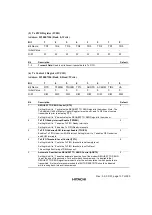
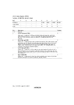
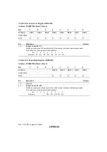
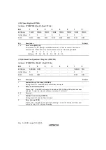
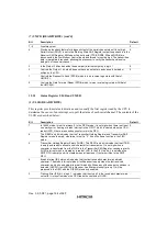
(22) Timer Register (ITMR)
Address: H'10007108 (Bank 2, Read/ Write)
Bit
7
6
5
4
3
2
1
0
Bit Name
TMR7
TMR6
TMR5
TMR4
TMR3
TMR2
TMR1
TMR0
Initial Value
0
0
0
0
0
0
0
0
R/W
R/W
R/W
R/W
R/W
R/W
R/W
R/W
R/W
Bit
Description
Default
7 - 0
Timer value (TMR[7:0])
Timer value, D0 - D7: Specify the initialization value for the down counter. The counter
has a period of 128us. When the counter reaches zero, an interrupt is generated.
Bit 7 6 5 4 3 2 1 0
Bit Name D7 D6 D5 D4 D3 D2 D1 D0
-
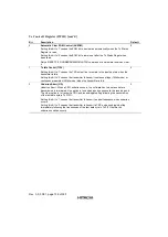
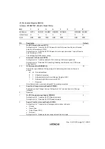
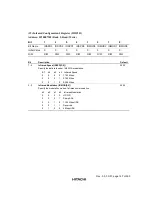
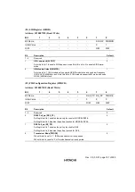
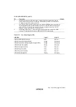
(23) Infrared Configuration 3 Register (IIRC3R)
Address: H'1000710A (Bank 2, Read/ Write)
Bit
7
6
5
4
3
2
1
0
Bit Name
SCDIEN SCD
-
-
-
-
TMIEN
TMI
Initial Value
0
0
-
-
-
-
0
0
R/W
R/W
R/W
-
-
-
-
R/W
R/W
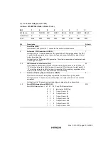
Bit
Description
Default
7
Enables Sharp CD Interrupt (SCDIEN)
Setting this bit to 1, enables Sharp Carrier Detect interrupts.
-
6
Sharp Carrier Detect (SCD)
When set to 1, this READ-only status bit indicates a 500KHz Sharp ASK carrier has been
detected. To clear the interrupt, software must write a 1 to this bit.
-
5 - 2
Reserved
-
1
Enables Timer Interrupt (TMIEN)
Setting this bit to 1 enables Timer Interrupt.
-
0
Timer Interrupt (TMI)
When set to 1, indicates a timer interrupt is pending. To clear the interrupt, software must
write a 1 to this bit. This bit is self-clearing.
-
Summary of Contents for HD64465
Page 25: ...Rev 3 0 03 01 page 6 of 390 ...
Page 59: ...Rev 3 0 03 01 page 40 of 390 ...
Page 97: ...Rev 3 0 03 01 page 78 of 390 ...
Page 147: ...Rev 3 0 03 01 page 128 of 390 ...
Page 199: ...Rev 3 0 03 01 page 180 of 390 ...
Page 247: ...Rev 3 0 03 01 page 228 of 390 ...
Page 385: ...Rev 3 0 03 01 page 366 of 390 ...
Page 389: ...Rev 3 0 03 01 page 370 of 390 ...
Page 409: ...Rev 3 0 03 01 page 390 of 390 ...

