Rev. 3.0, 03/01, page 231 of 390
Table 15.1
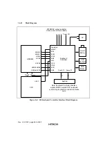
Pin Function of AFE Interface Module
Name
I/O
Pin Function
DOUT(RxD)
I
Serial Receive Data Input Pin, from AFE module
FS
I
Frame Sync Signal Input Pin
SCLK
I
Shift Clock Input Pin
DIN(TxD)
O
Serial Transmit Data Output Pin, to AFE module
RESETO# (CNT1)
O
External Chip Control Signal 1 Output Pin (RESETO#)
PWRDWNO#(CNT2)
O
External Chip Control Signal 2 Output Pin (PWRDWNO#)
RLYCNT
O
RLYCNT Control and Dial Pulse Output Pin
HC1
O
Hardware Control Signal 1 for STLC7546/7550
RING
I
Ringing Signal Input Pin
AFECK
I
Crystal Oscillator clock input Pin
AFECKE
I/O
Crystal Oscillator Output Pin
MCKO
O
Master Clock for Modem Pin
15.2
Register Description
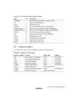
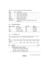
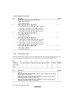
An AFE interface contains registers and buffers described in the table below.
Table 15.2
Registers of AFE Interface
Register or Buffer
Function
Access Size
Address
CTR
AFE Interface Control Register
16 bits
H'10003200
STR
AFE Interface Status Register
16 bits
H'10003202
TXDR
Transmit Data Register
16 bits
H'10003206
RXDR
Receive Data Register
16 bits
H'10003204
TXDB0,1
Transmit Data Buffers 0,1
16 bits
H'10003100 - 5F
TSFTR
Transmit Shift Register
Can not be accessed
*
RXDB0,1
Receive Data Buffers Register 0,1
16 bits
H'10003000 - 5F
RSFTR
Receive Shift register
Can not be accessed
*
Summary of Contents for HD64465
Page 25: ...Rev 3 0 03 01 page 6 of 390 ...
Page 59: ...Rev 3 0 03 01 page 40 of 390 ...
Page 97: ...Rev 3 0 03 01 page 78 of 390 ...
Page 147: ...Rev 3 0 03 01 page 128 of 390 ...
Page 199: ...Rev 3 0 03 01 page 180 of 390 ...
Page 247: ...Rev 3 0 03 01 page 228 of 390 ...
Page 385: ...Rev 3 0 03 01 page 366 of 390 ...
Page 389: ...Rev 3 0 03 01 page 370 of 390 ...
Page 409: ...Rev 3 0 03 01 page 390 of 390 ...

