Rev. 3.0, 03/01, page 254 of 390
17.4
Block Diagram
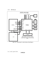
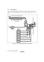
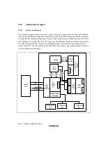
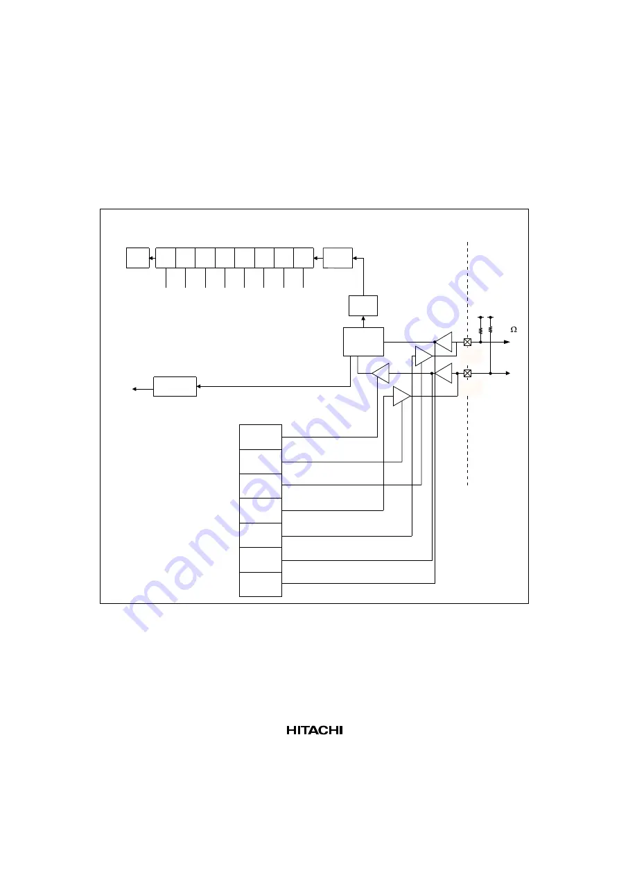
Figure 17-1 shows a block diagram of the PS/2 keyboard or mouse interface. When one byte of
data is received from the external keyboard or mouse, the interface generates an interrupt to the
CPU.
Start
Parity
2.2k
Stop
Receive
control
KBCIE
(MSCIE)
KBCOE
(MSCOE)
KBDOE
(MSDOE)
KBCD
(MSCD)
KBDD
(MSDD)
KBCS
(MSCS)
KBDS
(MSDS)
KBRDF
(MSDRDF)
KBCSR
(MSCSR)
0
1
2
3
4
5
6
7
8
Key buffer (reciver data shift register)
Internal data bus
0
interrupt
KBISR
(MSISR)
KBCSR
(MSCSR)
15
14
13
12
11
10
9
D0
D1
D2
D3
D4
D5
D6
D7
KBDATA
(MSDATA)
KBCK
(MSCK)
Figure 17.1 PS/2 Keyboard/Mouse Interface Block Diagram
Summary of Contents for HD64465
Page 25: ...Rev 3 0 03 01 page 6 of 390 ...
Page 59: ...Rev 3 0 03 01 page 40 of 390 ...
Page 97: ...Rev 3 0 03 01 page 78 of 390 ...
Page 147: ...Rev 3 0 03 01 page 128 of 390 ...
Page 199: ...Rev 3 0 03 01 page 180 of 390 ...
Page 247: ...Rev 3 0 03 01 page 228 of 390 ...
Page 385: ...Rev 3 0 03 01 page 366 of 390 ...
Page 389: ...Rev 3 0 03 01 page 370 of 390 ...
Page 409: ...Rev 3 0 03 01 page 390 of 390 ...

