Rev. 3.0, 03/01, page 337 of 390
19.2.2
A/D Control/Status Register (ADCSR)
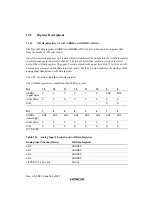
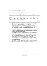
ADCSR is a 16-bit readable/writable register that selects the mode and controls the A/D converter.
ADCSR is initialized to H’0000 by a reset and is in STANDBY mode.
Bit
7
6
5
4
3
2
1
0
Bit Name
ADF
*
ADST
ADIS
*
TRGE
ADIE
SCAN
CH1
CH0
Initial Value
0
0
0
0
0
0
0
0
R/W
R/W
R/W
R/W
R/W
R/W
R/W
R/W
R/W
*
NOTE: Only 0 can be written to clear the flag bits.
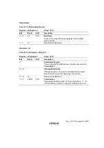
Bit
Description
Default
7
A/D End Flag (ADF): Indicates the end of A/D conversion. When set to 1: In Single mode,
A/D conversion ends. In Scan mode, A/D conversion ends in all selected channels. When
set to 0: Cleared by reading ADF while ADF = 1, then writing 0 in ADF.
0
6
A/D Start (ADST): Starts or stops A/D conversion. The ADST bit value remains at 1
during A/D conversion. It can also be set to 1 by external trigger input at the ADTRG pin.
When set to 1: In Single mode, A/D conversion starts; ADST is automatically cleared to 0
when conversion ends. In Scan mode, A/D conversion starts and continues, cycling
among the selected channels, until ADST is cleared to 0 by software, or by a reset, or by
switching to STANDBY mode.
0
5
Interrupt Status (ADIS): Indicates the status of A/D interrupt request. When the bit is 1,
interrupt request is active. When the bit is 0, interrupt request is inactive. If software writes
0 to this bit, it can disable the interrupt request.
0
4
Trigger Enable (TRGE): Enables or disable external triggering of A/D conversion. When
set to 1, A/D conversion starts at the falling edge of the external trigger signal (ADTRG).
When set to 0, A/D conversion cannot be externally triggered.
0
3
A/D Interrupt Enable (ADIE): Enables or disables the interrupt (ADI) requested at the
end of an A/D conversion. When this bit is set to 1, A/D end interrupt request (ADI) is
enabled. When this bit is set to 0, A/D end interrupt request (ADI) is disabled.
0
2
Scan Mode (SCAN): Selects single mode or scan mode. For further information on the
operation of these modes, see section 19.3 Operation on page 331. Clear the ADST bit
to 0 before switching the conversion mode. When this bit is set to 1 is Scan mode. Set this
bit to 0 to enter Single mode.
0
1 - 0
Channel Select 1 and 0 (CH1 and CH0): These bits and the SCAN bit select the analog
input channels. Clear the ADST bit to 0 before changing the selected channel.
0
Summary of Contents for HD64465
Page 25: ...Rev 3 0 03 01 page 6 of 390 ...
Page 59: ...Rev 3 0 03 01 page 40 of 390 ...
Page 97: ...Rev 3 0 03 01 page 78 of 390 ...
Page 147: ...Rev 3 0 03 01 page 128 of 390 ...
Page 199: ...Rev 3 0 03 01 page 180 of 390 ...
Page 247: ...Rev 3 0 03 01 page 228 of 390 ...
Page 385: ...Rev 3 0 03 01 page 366 of 390 ...
Page 389: ...Rev 3 0 03 01 page 370 of 390 ...
Page 409: ...Rev 3 0 03 01 page 390 of 390 ...

