Rev. 3.0, 03/01, page 57 of 390
6.3.4
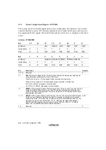
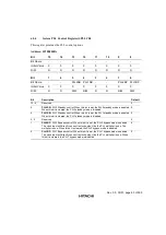
System Peripheral Clock Control Register (SPCCR)
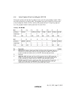
This register provides the function of peripheral clock control for each peripheral module. When
the peripheral module is in standby mode, the peripheral clock can be turned off to reduce more
power consumption, thanks to the free running of the peripheral clock. To stop the peripheral
clock, the peripheral module standby mode must be asserted first.
Address: H'10000006
Bit
15
14
13
12
11
10
9
8
Bit Name
ADCCLK -
UARTCLK PPCLK
FIRCLK
SIRCLK SCDICLK KBCCLK
Initial Value
0
0
0
0
0
0
0
0
R/W
R/W
R
R/W
R/W
R/W
R/W
R/W
R/W
Bit
7
6
5
4
3
2
1
0
Bit Name
USBCLK AFECLK -
-
-
-
UCKOSC AFEOSC
Initial Value
0
0
0
0
0
0
0
0
R/W
R/W
R/W
R
R
R
R
R/W
R/W
Bit
Description
Default
15
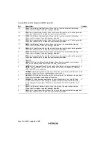
ADCCLK: A/D Controller Clock Control. When this bit is set, the A/D controller clock will
be halted. The A/D controller clock will run normally after this bit is cleared. Note that this
bit can be cleared only Twkst ms later, the UCKOSC bit has already been cleared.
0
14
Reserved
0
13
UARTCLK: UART Controller Clock Control. When this bit is set, the UART clock will be
halted. The UART channel 0 clock will run normally after this bit is cleared. Note that this
bit can be cleared only Twkst ms later, the UCKOSC bit has already been cleared.
0
12
PPCLK: Parallel Port Controller Clock Control. When this bit is set, the PP clock will be
halted. The PP clock will run normally after this bit is cleared. Note that this bit can be
cleared only Twkst ms later, the UCKOSC bit has already been cleared.
0
Summary of Contents for HD64465
Page 25: ...Rev 3 0 03 01 page 6 of 390 ...
Page 59: ...Rev 3 0 03 01 page 40 of 390 ...
Page 97: ...Rev 3 0 03 01 page 78 of 390 ...
Page 147: ...Rev 3 0 03 01 page 128 of 390 ...
Page 199: ...Rev 3 0 03 01 page 180 of 390 ...
Page 247: ...Rev 3 0 03 01 page 228 of 390 ...
Page 385: ...Rev 3 0 03 01 page 366 of 390 ...
Page 389: ...Rev 3 0 03 01 page 370 of 390 ...
Page 409: ...Rev 3 0 03 01 page 390 of 390 ...

