Rev. 3.0, 03/01, page 59 of 390
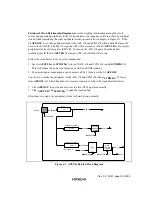
Peripheral Clock Relationship Diagrams shows the working relationship among the clock
source and generated peripheral clocks. It also indicates the sequence of turning off one peripheral
clock without interfering the other peripheral clocks operation. For example, in Figure 6-1, If the
bit AFEOSC is set, then peripheral clocks like AFE_clk and SCDI_clk will be halted because the
source clock AFECK is halted. To stop the AFE_clk, users can set the bit AFECLK in the system
peripheral clock control register (SPCCR). To turn on the AFE_clk again from the halted
condition, just let the bit AFECLK be cleared, AFE_clk will then start to run.
Follow the steps below to save power consumption:
1. Set bits AFECLK and SCDICLK to turn off AFE_clk and SCDI_clk (under SCDICKS=0).
This will reduce the power consumption of AFE and SCDI modules.
2. Even more power consumption can be saved on PLL1 if users set the bit AFEOSC.
Conversely, to make the peripheral clocks AFE_clk and SCDI_clk (under SCDICKS=0) to run
from AFEOSC bit, which has been set, users are required to follow the steps described below:
1. Clear AFEOSC, then wait about t
PLL
ms to allow PLL1 operate normally.
2. Clear AFECLK and SCDICLK to open the clock gating.
After these two steps, the peripheral clocks will start to run normally.
12.288Mhz
36.8Mhz
AFEOSC
AFECK
x3
PLL1
x(1/3)
Frequency divider
12.288Mhz
Mux
12Mhz
SCDICKS
SCDI_clk
SCDICLK
ACCLK
From Figure 2.
x(1/4)
Frequency divider
AFE_clk
Clock
Gating
Control
Clock
Gating
Control
AFECLK
9.2Mhz
Figure 6.1 AFECK Related Clock Diagram
Summary of Contents for HD64465
Page 25: ...Rev 3 0 03 01 page 6 of 390 ...
Page 59: ...Rev 3 0 03 01 page 40 of 390 ...
Page 97: ...Rev 3 0 03 01 page 78 of 390 ...
Page 147: ...Rev 3 0 03 01 page 128 of 390 ...
Page 199: ...Rev 3 0 03 01 page 180 of 390 ...
Page 247: ...Rev 3 0 03 01 page 228 of 390 ...
Page 385: ...Rev 3 0 03 01 page 366 of 390 ...
Page 389: ...Rev 3 0 03 01 page 370 of 390 ...
Page 409: ...Rev 3 0 03 01 page 390 of 390 ...


