Chapter 5 Master Module Specifications
5-1
Chapter 5
Master Module Specifications
5.1 Outlook/Shape
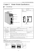
Name and function of each part
Type
EH-RMD
Weight
Approx. 0.13 kg
Dimensions (mm)
1] LED cover
5] Lock button
3] Reset switch
2] DIP switch
4] Communication connector
100
30
95
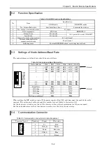
No. Name
Function
Remark
1] LED
cover
This is the cover for the LEDs that display the network status
and error information.
-
2]
DIP switch
Sets the node address and communication speed.
-
3]
Reset switch
Resets the module.
-
4]
Communication
connector
Connects to the network.
Use the packaged
connector.
5] Lock
button
This is used when removing the module from the base unit.
After it is mounted on the base unit, the attachment can be
reinforced using screws. In this case, use M4 x 10 mm (0.39
in.) screws.
-
- -
The DIP switch on the side of the module is covered by a
protective cover, as it is not used. Do not remove the cover.
-
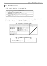
MODE select
EH-RMD is possible to select the LINK mode or REMOTE mode.
EH-RMD supports REMOTE mode from SOFTWARE VER.02 or more.
Less SOFTWARE VER.02, it supports only LINK mode. Please do not change this mode select switch.
And the CPU module which supports remote mode is EH-CPU 516/548.
MODE
LINK mode
REMOTE mode
Note
MODE select
switch
Please
turn
off
the power for
changing
mode.
MODE select switch
4 3 2 1
ON
4 3 2 1
ON


