Chapter 5 Master Module Specifications
5-2
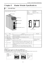
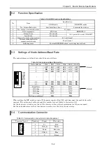
5.2 Function
Specification
Table 5.1 EH-RMD Function Specifications
Specification
No. Item
LINK mode
REMOTE mode
1
No. of installed units
2 modules/basic base
4 modules/basic base
2
No. of slave- connected units
63 units
3
I/O assignment
CPU link
REMOTE 2
4
Output data
256 words
5
Input data
256 words
1024 points(64 words) IN&OUT
6
Internal current consumption
450 mA (max)
7
Current consumption on
communication side
80 mA (max)
8 Self-diagnosis
System
ROM/RAM check, watchdog timer check
5.3
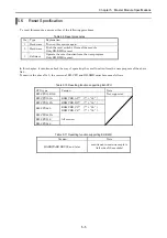
Settings of Node Address/Baud Rate
The node addresses and baud rate should be set as follows.
Table 5.2 Node Address/Baud Rate setting
Node address
NA1
NA2
NA4
NA8 NA16 NA32
0
OFF OFF OFF OFF OFF OFF
1
ON
OFF OFF OFF OFF OFF
2 OFF
ON
OFF OFF OFF OFF
...
...
...
...
...
...
...
62 OFF
ON ON ON ON ON
63
ON ON ON ON ON ON
Baud Rate
DR0
DR1
125 kbps
OFF
OFF
250 kbps
ON
OFF
500 kbps
OFF
ON
NA32
NA16
NA8
NA4
MA2
NA1
DR1
DR0
→
ON
Setting prohibited
ON ON
When setting the DIP switches, turn off the power supply of the PLC and disconnect the module from the
network. The setting isn't reflected until the module is reset ( Refer to the section 5.6).
Set the baud rate in such a way that all the devices on the network communicate at the same speed.
Set the node addresses for the other devices in such a way that they do not overlap.
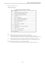
5.4 Communication
Connector
Table 5.3 Communication connector terminal arrangement
Terminal layout
Number
Signal
Wire color
5 V+ Red
4 CAN_H White
3 Drain Bare
wire
2 CAN_L Blue
5
1
4
3
2
1 V- Black
Default
Default


