Chapter 5 Master Module Specifications
5-3
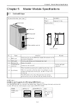
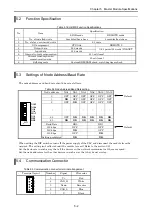
5.5 LED
Specification
Table 5.4 LED Specification
Outlook of LED
Symbol Description Color
NS
Indicates the status of the network.
Green/red
MS
Indicates the status of the communication
interface board
Green/red
RUN
Indicates the operation mode.
Green
NS
MS STATUS
RUN
EH-RMD
DEVICENET
STATUS
Indicates the status of the PLC interface board.
Green/red
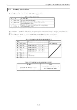
(1) MS/NS
Table 5.5 MS/NS LED Specification
NS
MS
Lit in Green
Flashing in
Green
Lit in Red
Flashing in
Red
Turned off
Lit
in
Green
1 2 4 5 3
Lit in Red
-
- - - 6
Turned
off
- - - - 7
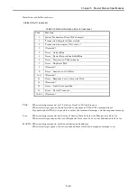
Table 5.6 MS/NS LED detail
No. Display status
Description
Action to take
1
MS lit in green
NS lit in green
I/O connection established
-
2
MS lit in green
NS flashing
in
green
I/O connection not established
Check all connected slaves.
Check the scan list from the
configurator.
3
MS lit in green
NS turned
off
Checking node address overlap/no
power supply to the network
Check the communication speed
of each device.
Check that 24 V DC is supplied.
4
MS lit in green
NS lit in red
Node address overlaps/it is detected
that the bus is not functioning
Check the node address and
communication speed of each
device.
Check to see if a cable is broken.
Check that the terminal resistor
is connected properly.
Check that the cable length is
within the specification range.
5
MS lit in green
NS flashing in red
Communication timeout/
Scan List unmatched
Check the communication speed
of each device.
Check to see if a cable is broken.
Check that the terminal resistor
is connected properly.
Check that the cable length is
within the specification range.
Please check that the node
registered into the Scan list is
connected.
6
MS lit in red
NS turned
off
Communication board hardware
error
Replace the module.
7
MS turned
off
NS turned
off
No power supply to the PLC/waiting
for module initialization
Check that the specified voltage
is supplied to the power module
of the PLC.
Please check that I/O assignment
is done.


