Chapter 6 Slave Controller Specifications
6-4
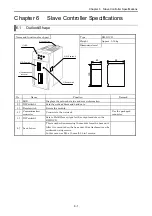
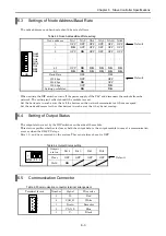
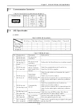
6.6 LED
Specification
Table 6.6 LED Specification
Outlook of LED
Symbol
Description
Color
NS
Indicates the status of the network.
Green/red
MS
Indicates the status of the communication
interface board.
Green/red
STATUS
Indicates the status of the PLC interface
board.
Green/red
None Not
used
―
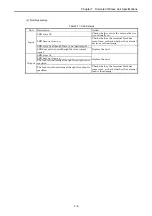
(1) MS/NS
Table 6.7 MS/NS LED Specification
NS
MS
Lit in Green
Flashing in
Green
Lit in Red
Flashing in
Red
Turned off
Lit
in
Green
1 2 4 5 3
Lit in Red
―
―
―
―
6
Turned off
―
―
―
―
7
Table 6.8 MS/NS LED detail
No. Display status
Description
Action to take
1
MS lit in green
NS lit in green
I/O connection established
2
MS lit in green
NS flashing in green
I/O connection not established
Confirm that the DeviceNet master
is working normally.
3
MS lit in green
NS turned
off
Checking node address overlap/
no power supply to the network
Check the communication speed of
each device.
Check that 24 V DC is supplied.
4
MS lit in green
NS lit in red
Node address overlaps/
it is detected that the bus is not
functioning
Check the node address and
communication speed of each device.
Check to see if a cable is broken.
Check that the terminal resistor is
connected properly.
Check that the cable length is
within the specification range.
5
MS lit in green
NS flashing in red
Communication timeout
Check the communication speed of
each device.
Check to see if a cable is broken.
Check that the terminal resistor is
connected properly.
Check that the cable length is
within the specification range.
6
MS lit in red
NS turned
off
Communication board hardware
error
Replace the module.
7
MS turned
off
NS turned
off
No power supply to the PLC/
waiting for module initialization
Check that the specified voltage is
supplied to the power module of the
PLC.
Check that the LINK is assigned in
the I/O assignment for the CPU.
DEVICENET
NS M S STATUS
EH-IOCD


