Chapter 8 Starting Up
8-15
How to calculate the I/O data size
Any I/O data size within the following range can be set for the EH-IOCD.
Input (byte)
Output (byte)
Default 8
8
Allowable setting range
0-255
0-255
Set the size of input/output according to the module actually used.
See Section 6.2 for the I/O data size used by each module.
A calculation example is shown below.
Input size:
EH-XD8 + EH-CU + EH-AX44
2 + 10 + 16 = 28 bytes
Output size: EH-YTP32 + EH-CU + EH-YTP64
4 + 6 + 8 = 18 bytes
3. Mapping of input data
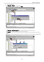
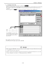
Display the Input tag, and (1)click each device followed by (2) [AutoMap].
First enter the offset address in Start Byte; then it becomes possible to map the input data to the selected area.
(The maximum input size of the EH-RMD is 512 bytes. Set Start Byte in such a way that this size is not
exceeded.)
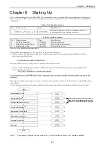
The data mapped in the Input tag is mapped to the WL area as follows.(in case of LINK mode)
WL200
WL201
If the EH-RMD is mounted in the slot
corresponding to the second link area,
the mapping can be started from
WL1200.
EH-PSA
EH-IOCD
EH-XD8
EH-YTP32
EH-CU
EH-AX44
EH-YTP64
15
0
(1)
(2)
(3)

