Chapter 8 Starting Up
8-16
4. Mapping of output data
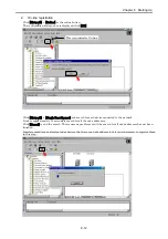
Display the Output tag, and click each device followed by [AutoMap].
First enter the offset address in Start Byte; then it becomes possible to map the output data to the selected area.
(The maximum output size of the EH-RMD is 512 bytes. Set Start Byte in such a way that this size is not
exceeded.)
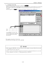
The data mapped in the Output tag is mapped to the WL area as follows.(in case of LINK mode)
WL0
WL1
If the EH-RMD is mounted in the
slot corresponding to the second link
area, the mapping can be started
from WL1000.
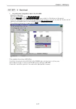
This completes the creation of the scan list.
Click [OK] and exit the property screen of the EH-RMD.
Caution
When mapping the EH-IOCD, set the correct sizes of the I/O modules to be mounted. Data will not be input
or output if the sizes are set incorrectly.
Only the actually mounted modules are mapped even if modules are mounted on both sides of a vacant slot.
For more information, see Section 11.3, “Mapping Specification of EH-IOCD.”
15
0


