Chapter 13 Mounting and Wiring
13-1
Chapter 13 Mounting and Wiring
13.1 Mounting the Module
2]
1]
(1) Mounting
1] Hook the claw at the lower section of the module
to the hole in the base.
2] Press in the upper side of the module until it
clicks.
Note 1: After mounting the module, check to make
sure it does not come out.
2]
1]
3]
(2) Removing
1] Push in the lock button.
2] While the lock button pushed in, pull the top of
the module toward the front.
3] Raise it toward the top and pull it out.
13.2 Wiring to the Power Module
(1) For power supply wiring, use a cable of 2
mm
2
or more to prevent a voltage drop.
(2) The function ground terminal (FE terminal)
should use cable of 2 mm
2
or more and Class
D grounding (100
Ω
or less). The
appropriate distance for ground cable is
within 20 m.
1] Grounding of instrumentation panel
and relay panel can be shared.
2] Avoid joint grounding with equipment
that may generate noise such as
high-frequency heating furnace, large
scale power panel (several kW or more),
thyristor exchanger, electric welders,
etc.
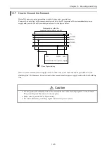
3] Be sure to connect a noise filer (NF) to
the power cable.
(3) The terminal screw is an M3. When wiring,
tighten screws within a torque range of 0.49
to 0.78 N·m.
(4) Use the same power supply system for the
basic and expansion units.
0 1
4 5
8 9
12 13
PORT
1
PORT
2
EH-150
HITACHI
POWE
R
Leak
breaker
100 V AC
∼
200 V AC
Noise
filter
Insulation
transformer
with shield


