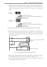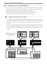
3 – 1
Chapter 3 Name and function of each part
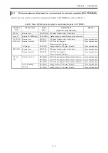
3.1
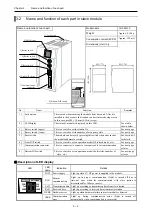
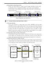
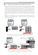
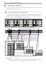
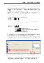
Name and function of each part in master module
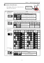
Description of LED display
Name and function of each part
Model name
EH-TRMME
Weight
Approx. 0.12 kg
Consumption current (5VDC)
Approx. 150 mA
Dimensions (mm (in.))
30 (1.18)
100 (
3
.94)
95 (3.74)
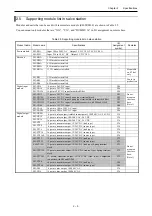
No. Name
Function
Remarks
1]
Lock button
This is used when removing the module from base unit. After it is
installed to the base unit, the fixation can be reinforced using screws. In
this case, use M4
×
10 mm (0.39 in.) screw.
2]
LED display
The status of module is displayed on this LED.
See a table shown
below.
3]
Rotary switch (upper)
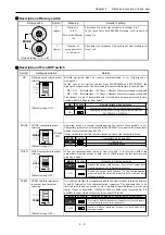
This is a switch to set I/O assignment for master module.
See next page.
4]
Rotary switch (lower)
This is a switch to set the number of connected slave modules.
See next page.
5]
Reset switch
The module can be reset by pressing this switch when error such as the
module abnormal occurred.
See Section 6.4 for
details.
6]
Front DIP switch
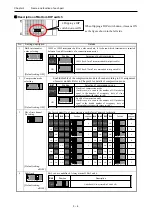
This is a switch to set an operation mode (HS refresh mode, etc.).
See next page.
7]
Connector
This is a connector to connect a twist-pair cable for connecting slave
modules.
See next page or later.
8]
Side DIP switch
This is a switch to set an operation mode (the last channel number of
master, etc.).
See next page or later.
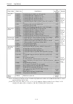
LED
LED
name
Indication Details
POW
Power supply
Light up when 5V DC power is supplied to the module.
RUN
Normal
communication
Light up in proper communication. (Light is turned off due to
time-out error when the communication with slave station is
discontinued for 500ms or more.)
TxD Transmission
data Light
up according to transmission data from master station.
RxD
Received data
Light up according to received data from slave station.
HERR Hardware error
Light up when hardware failure in master module is detected.
REMOTE
EH-TRMME
RUN
RxD
HERR CERR
POW
TxD
CERR Communication
error
Light up during communication error. (Light is turned off
automatically when communication is recovered.)
1] Lock button
7] Connector (socket)
3] Rotary switch (upper)
2] LED display
4] Rotary switch (lower)
5] Reset switch
6] Front DIP switch
8] Side DIP switch

