Chapter 3 Name and function of each part
3 – 5
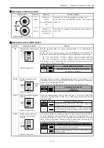
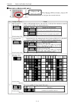
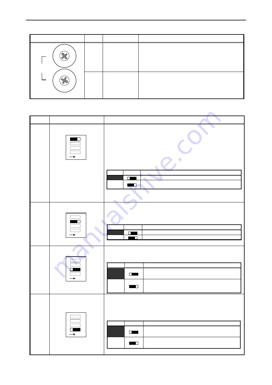
Description of Rotary switch
Rotary switch
Symbol
Meaning
Details of setting
U
(upper)
Station No.
(0 to 7)
Mix with EM mode
(E)
The station No. of the slave modules is set from 0 to 7.
In the case of mix with EM/EM-II station, set E in spite of
station No..
4
C
0
8
1
2
3
9
A
B
5
6
7
D
E
F
MODE
U
L
4
C
0
8
1
2
3
9
A
B
5
6
7
D
E
F
[Default setting: U=0, L=0]
L
(lower)
Number of
occupancy slots
(1 to 8 units)
The number of occupancy slots used in the slave station is set
from 1 to 8.
Description of Front DIP switch
Symbol Setting
description
Details
HS
HS (high-speed refresh mode)
selecting
ON
4
3
2
1
HS
MODE
HOLD
TERM
[Default setting: ON]
Refresh operation mode on remote communication is set (High-speed or
Low-speed).
In the case of all stations consist from EH-TRMME and EH-TRMLE, the
high-speed refresh mode can be selectable. Remote refresh time is shown below.
HS = ON:
Refresh time = 0.156 ms
×
Number of master occupancy channels
HS = OFF: Refresh time = 0.338 ms
×
Number of master occupancy channels
The channel is unit of transmitted and received data between master and slave
stations. Refer to Chapter 4 for detail.
HS
Position
Remote refresh mode selection
OFF
Low-speed refresh mode (for low-speed remote modules)
ON
High-speed refresh mode (for high-speed remote modules
EH-TRMME, EH-TRMLE)
MODE
MODE (compatible mode)
selecting
ON
4
3
2
1
HS
MODE
HOLD
TERM
[Default setting: ON]
Operation mode on remote communication for remote slave module is set.
Compatible mode allows slave module(EH-TRMLE) to connect with master/slave
stations for series other than EH-150.
Always make sure that this switch is turned on, that is the compatible mode.
MODE
Position
Compatible mode selection
OFF
Undefined
ON
Compatible mode
HOLD
HOLD (output hold function)
selecting
ON
4
3
2
1
HS
MODE
HOLD
TERM
[Default setting: OFF]
When the communication time-out error occurred, it is selected whether the
output data from the master is held or not. (Hold means the last data received
properly is fixed.)
HOLD
Position
Output hold function selection
OFF
Disable the output hold function (Turn off all output data
from the master at the communication error.)
ON
Enable the output hold function (At the communication
error, output data from the master is held with last data
received properly.)
TERM TREM
(built-in
terminator
insertion / non-insertion)
selecting
ON
4
3
2
1
HS
MODE
HOLD
TERM
[Default setting: OFF]
It is selected whether the terminator build in the slave module is inserted between
A and B terminals of the communication connector. The terminator has to be
inserted in both ends of master or slave module connected through a twist-pair
cable. 2 types of terminator, 100
Ω
and 150
Ω
, are build in the slave module. It is
possible to select which to insert by the bottom DIP switch.
TERM
Position
Selection of insertion / non-insertion of terminator
OFF
Not insert a built-in terminator. (in unnecessary case because
it is not both ends of a twist-pair cable)
ON
Insert a built-in terminator. (when it is both ends of a
twist-pair cable)
Always
ON

