Chapter 5 Installation and Turning power supply on
(2) Connection of Communication cable
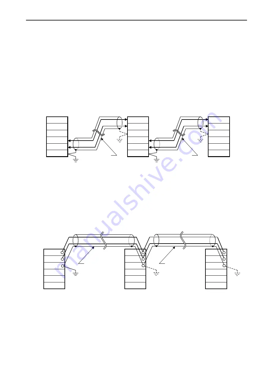
Use a shielded twist-pair cable for communication and ground the shielded cable at single end as a general rule.
However, ground the cable appropriately according to noisy environment because the effect may depend on how to
ground. Branch of cable is not allowed. The following figure shows an example that the master module is connected to
an end of the twist-pair cables. The master module can be also arranged not to an end but to the middle.
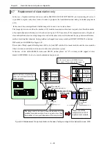
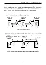
[Connection method 1] Normal connection method
Even if a slave module is powered off, it is possible to continue communication between a master module and
other slave modules while operating. Please refer to Section 6.5 for details.
Master (EH-TRMME)
Communication
connector
6] SHD
5] B
4] A
3] SHD
2] B
1] A
6] SHD
5] B
4] A
3] SHD
2] B
1] A
Slave (EH-TRMLE)
Communication
connector
No. is the pin
number.
6] SHD
5] B
4] A
3] SHD
2] B
1] A
Slave (EH-TRMLE)
Communication
connector
No. is the pin
number.
No. is the pin
number.
Shielded
twist-pair cable
Shielded
twist-pair cable
Figure 5.5
Normal connection method
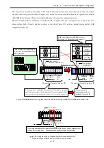
[Connection method 2] Connection method when enabling the replacement of slave module while operating
By plugging 2 cables to the connector beforehand, the disconnected state can be prevented and the operation can
be continued even if the connector is pulled out of the slave module.
Master (EH-TRMME)
Communication
connector
Slave (EH-TRMLE)
Communication
connector
Slave (EH-TRMLE)
Communication
connector
6] SHD
5] B
4] A
3] SHD
2] B
1] A
6] SHD
5] B
4] A
3] SHD
2] B
1] A
6] SHD
5] B
4] A
3] SHD
2] B
1] A
No. is the pin number.
No. is the pin number.
No. is the pin number.
Shielded
twist-pair cable
Shielded
twist-pair cable
Figure 5.6
Connection method when enabling the replacement of slave module while operating
5 – 3


