Chapter 6 Error indication and Countermeasure
6.6 Troubleshooting
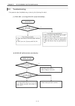
The procedure about troubleshooting is shown by the following flow chart.
(1) POW LED : as turning off (5V DC power abnormality).
POW LED
lit
Y
POW LED
of the power module is lit
N
Check the power supply module
a) AC power supply voltage (at the input terminal)
b) Capacity of power supply module
c) DC power supply voltage (at the output terminal)
d) Supply power only for the power supply module
e) Connection between the power module and base
unit
Check the remote module
a) Connection between the remote module and base
unit.
b) Check connecter of remote module for base.
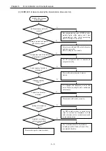
(2) HERR LED lights (hardware abnormality).
HERR LED lights
N
Y
It occurs even if turning on
power supply again
Setting of rotary switch
is correct
Set rotary switch correctly.
Refer to Chapter 3 for details.
Y
N
It is thought the temporary error by the
noise. Please investigate, and confirm the
noise source.
Please exchange the remote module.
6 – 6

