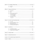
Chapter 10
PLC Installation, Mounting, Wiring...................................................................................... 10-1 to 10-8
10.1 Installation ............................................................................................................................. 10-1
10.2 Wiring .................................................................................................................................... 10-3
Chapter 11
Communication Specifications............................................................................................ 11-1 to 11-10
11.1 Port function .......................................................................................................................... 11-1
11.2 Port 1...................................................................................................................................... 11-1
11.3 Port 2...................................................................................................................................... 11-3
11.4 General purpose port (Port 1,2) ............................................................................................. 11-4
11.5 Modem Control Function....................................................................................................... 11-5
11.5.1 Configuration.............................................................................................................. 11-5
11.5.2 AT Commands............................................................................................................ 11-5
11.6 Connecting to the Ports .......................................................................................................... 11-8
11.6.1 Port 1 .......................................................................................................................... 11-8
11.6.2 Port 2 .......................................................................................................................... 11-9
Chapter 12
Error Code List and Special Internal Outputs ..................................................................... 12-1 to 12-14
12.1 Error Codes............................................................................................................................ 12-1
12.2 Syntax and Assembler Error Codes........................................................................................ 12-3
12.3 Operation Error Codes ........................................................................................................... 12-4
12.4 Bit Special Internal Output Area............................................................................................ 12-5
12.5 Word Special Internal Output Area........................................................................................ 12-9
Chapter 13
Troubleshooting .................................................................................................................. 13-1 to 13-16
13.1 Error Display and Actions...................................................................................................... 13-1
13.2 Checklist when Abnormality Occurred .................................................................................. 13-5
13.3 Procedures to Solve Abnormality .......................................................................................... 13-6
Chapter 14
Operation Examples ............................................................................................................ 14-1 to 14-16
Chapter 15
Daily and Periodic Inspections.............................................................................................. 15-1 to 15-2
Appendix 1 H-Series Instruction Support Comparison Chart.................................................................................A-1
Appendix 2 Standards...........................................................................................................................................A-11
Summary of Contents for HIDIC MICRO-EH
Page 1: ...HITACHI PROGRAMMABLE CONTROLLER APPLICATION MANUAL NJI 350B X ...
Page 12: ...MEMO ...
Page 14: ...Chapter 1 Features 1 2 MEMO ...
Page 50: ...Chapter 4 Product lineup and wiring 4 18 MEMO ...
Page 196: ...Chapter 5 Instruction Specifications 5 146 ...
Page 263: ...Chapter 11 Communication Specifications 11 10 MEMO ...

